
3255 Manual
Page 1
® GARAGE DOOR OPENER Models 3245 1/3 HP 3255 1/2 HP 3255-2 1/2 HP For Residential Use Only The Chamberlain Group, Inc. 845 Larch Avenue Elmhurst, Illinois 60126-1196 www.liftmaster.com Owner's Manual ■ Please read this manual and the enclosed safety materials carefully! ■ Fasten the manual near the garage door after installation. ■ The door WILL NOT CLOSE unless...
® GARAGE DOOR OPENER Models 3245 1/3 HP 3255 1/2 HP 3255-2 1/2 HP For Residential Use Only The Chamberlain Group, Inc. 845 Larch Avenue Elmhurst, Illinois 60126-1196 www.liftmaster.com Owner's Manual ■ Please read this manual and the enclosed safety materials carefully! ■ Fasten the manual near the garage door after installation. ■ The door WILL NOT CLOSE unless...
3255 Manual
Page 2
... System 25 Operation 26-30 Operation safety instructions 26 Using your garage door opener 26 Using the wall-mounted door control 27 To open the door manually 27 Care of damage to your garage door and/or the garage door opener if you do not comply with the instructions and warnings ... Motor unit assembly parts 34 Accessories 35 Repair Parts and Service 36 Warranty 36 INTRODUCTION Safety Symbol and Signal Word Review This garage door opener has been designed and tested to offer safe service provided it is installed, operated, maintained and tested in strict accordance ...
... System 25 Operation 26-30 Operation safety instructions 26 Using your garage door opener 26 Using the wall-mounted door control 27 To open the door manually 27 Care of damage to your garage door and/or the garage door opener if you do not comply with the instructions and warnings ... Motor unit assembly parts 34 Accessories 35 Repair Parts and Service 36 Warranty 36 INTRODUCTION Safety Symbol and Signal Word Review This garage door opener has been designed and tested to offer safe service provided it is installed, operated, maintained and tested in strict accordance ...
3255 Manual
Page 3
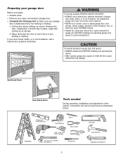
... which are under EXTREME tension. • Disable ALL locks and remove ALL ropes connected to garage door BEFORE installing and operating garage door opener to make sure your garage door is balanced and is not sticking or binding: 1. To prevent damage to garage door and opener: • ALWAYS disable locks BEFORE installing and operating the opener. • ONLY...
... which are under EXTREME tension. • Disable ALL locks and remove ALL ropes connected to garage door BEFORE installing and operating garage door opener to make sure your garage door is balanced and is not sticking or binding: 1. To prevent damage to garage door and opener: • ALWAYS disable locks BEFORE installing and operating the opener. • ONLY...
3255 Manual
Page 4
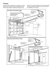
... Reversing Sensor Safety Reversing Sensor Gap between floor and bottom of Garage Door Extension Spring OR Torsion Spring Wallmounted Door Control Access Door --- --- -- Motor Unit Wallmounted Door Control Access Door ONE-PIECE DOOR WITH TRACK Slack in chain tension is normal when garage door is required. Survey your garage area to see if any of the conditions below apply to...
... Reversing Sensor Safety Reversing Sensor Gap between floor and bottom of Garage Door Extension Spring OR Torsion Spring Wallmounted Door Control Access Door --- --- -- Motor Unit Wallmounted Door Control Access Door ONE-PIECE DOOR WITH TRACK Slack in chain tension is normal when garage door is required. Survey your garage area to see if any of the conditions below apply to...
3255 Manual
Page 5
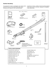
...Conductor Bell Wire White & White/Red? contain the motor unit and all parts illustrated below . 3245 (1), 3255 (1), 3255-2 (2) LOCK LIGHT Multi-Function Door Control Panel : SECURITY ® Single-Button Remote Control Remote Control Visor Clip Chain Sprocket Cover Styrofoam Motor Unit... (30) Ring Fastener (3) Drywall Anchors (2) Rail Grease Carriage Bolt 1/4"-20x1/2" (2) Wing Nut 1/4"-20 (2) Rope Handle 5 Straight Door Arm Section Carton Inventory Your garage door opener is packaged in the foam. Hardware for installation Accessories will depend on the model purchased.
...Conductor Bell Wire White & White/Red? contain the motor unit and all parts illustrated below . 3245 (1), 3255 (1), 3255-2 (2) LOCK LIGHT Multi-Function Door Control Panel : SECURITY ® Single-Button Remote Control Remote Control Visor Clip Chain Sprocket Cover Styrofoam Motor Unit... (30) Ring Fastener (3) Drywall Anchors (2) Rail Grease Carriage Bolt 1/4"-20x1/2" (2) Wing Nut 1/4"-20 (2) Rope Handle 5 Straight Door Arm Section Carton Inventory Your garage door opener is packaged in the foam. Hardware for installation Accessories will depend on the model purchased.
3255 Manual
Page 6
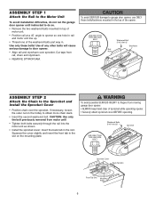
.... • REMOVE STYROFOAM. Use only these bolts! ASSEMBLY STEP 1 Attach the Rail to the Motor Unit To avoid installation difficulties, do not run the garage door opener until instructed to do so. • Remove the two washered bolts mounted in top of motor unit. • Position rail at a 45˚... attach sprocket cover BEFORE operating. Squeeze the cover slightly and insert the front tab in the slot on the trolley to fingers from moving garage door opener: • ALWAYS keep hand clear of the washered bolts part way in the top of any other bolts will cause serious damage to...
.... • REMOVE STYROFOAM. Use only these bolts! ASSEMBLY STEP 1 Attach the Rail to the Motor Unit To avoid installation difficulties, do not run the garage door opener until instructed to do so. • Remove the two washered bolts mounted in top of motor unit. • Position rail at a 45˚... attach sprocket cover BEFORE operating. Squeeze the cover slightly and insert the front tab in the slot on the trolley to fingers from moving garage door opener: • ALWAYS keep hand clear of the washered bolts part way in the top of any other bolts will cause serious damage to...
3255 Manual
Page 7
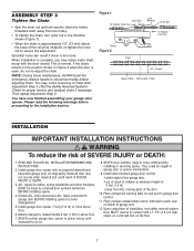
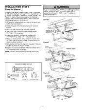
... chain droop with a 1-1/2" (3.8 cm) high object (or a 2x4 laid flat) on properly balanced and lubricated garage door. Please read the following warnings before proceeding to disconnect trolley before adjusting chain. READ AND FOLLOW ALL INSTALLATION WARNINGS AND INSTRUCTIONS...83 m) above floor. 6. Place entrapment warning label on inside of garage door. 12. When installation is open, do so. 8. ALL repairs to garage door control. 11. Install wall-mounted garage door control: • within sight of the garage door. • out of reach of children at its midpoint, re-tighten...
... chain droop with a 1-1/2" (3.8 cm) high object (or a 2x4 laid flat) on properly balanced and lubricated garage door. Please read the following warnings before proceeding to disconnect trolley before adjusting chain. READ AND FOLLOW ALL INSTALLATION WARNINGS AND INSTRUCTIONS...83 m) above floor. 6. Place entrapment warning label on inside of garage door. 12. When installation is open, do so. 8. ALL repairs to garage door control. 11. Install wall-mounted garage door control: • within sight of the garage door. • out of reach of children at its midpoint, re-tighten...
3255 Manual
Page 8
...used if mounting header bracket or 2x4 into masonry. • NEVER try to loosen, move or adjust garage door, springs, cables, pulleys, brackets, or their hardware, ALL of which apply to your garage, use lag screws (not provided) to securely fasten the 2x4 to gain approximately 1/2" (1 cm)). ...the ceiling (see page 9) when clearance is minimal. (It may be mounted on header wall or ceiling, otherwise garage door might not reverse when required. Open your door to structural support on the wall upside down if necessary, to structural supports as shown. DO NOT install header ...
...used if mounting header bracket or 2x4 into masonry. • NEVER try to loosen, move or adjust garage door, springs, cables, pulleys, brackets, or their hardware, ALL of which apply to your garage, use lag screws (not provided) to securely fasten the 2x4 to gain approximately 1/2" (1 cm)). ...the ceiling (see page 9) when clearance is minimal. (It may be mounted on header wall or ceiling, otherwise garage door might not reverse when required. Open your door to structural support on the wall upside down if necessary, to structural supports as shown. DO NOT install header ...
3255 Manual
Page 9
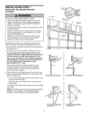
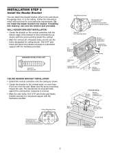
...Structural Support Header Bracket CEILING MOUNT ONLY UP Vertical Centerline of Garage Door Lag Screws 5/16"-9x1-5/8" Door Spring Horizontal Line Highest Point of Garage Door Travel Garage Door Vertical Centerline of Garage Door 9 Follow the instructions which will work best for ceiling mount... holes designated for your particular requirements. Header Bracket Vertical Centerline of Garage Door UP Lag Screws 5/16"-9x1-5/8" Garage Door Header Wall Vertical Centerline of Garage Door 6" (15 cm) Maximum Door Spring - WALL HEADER BRACKET INSTALLATION • Center the bracket on...
...Structural Support Header Bracket CEILING MOUNT ONLY UP Vertical Centerline of Garage Door Lag Screws 5/16"-9x1-5/8" Door Spring Horizontal Line Highest Point of Garage Door Travel Garage Door Vertical Centerline of Garage Door 9 Follow the instructions which will work best for ceiling mount... holes designated for your particular requirements. Header Bracket Vertical Centerline of Garage Door UP Lag Screws 5/16"-9x1-5/8" Garage Door Header Wall Vertical Centerline of Garage Door 6" (15 cm) Maximum Door Spring - WALL HEADER BRACKET INSTALLATION • Center the bracket on...
3255 Manual
Page 10
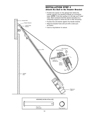
... is in the way you'll need help. Garage Door Ring Fastener Rail Header Bracket Clevis Pin 5/16"x2-3/4" Chain Pulley Bracket Rail Temporary Support HARDWARE SHOWN ACTUAL SIZE Clevis Pin 5/16"x2-3/4" 10 Ring Fastener Have someone hold the opener securely on the garage floor below the header bracket. Use packing material...
... is in the way you'll need help. Garage Door Ring Fastener Rail Header Bracket Clevis Pin 5/16"x2-3/4" Chain Pulley Bracket Rail Temporary Support HARDWARE SHOWN ACTUAL SIZE Clevis Pin 5/16"x2-3/4" 10 Ring Fastener Have someone hold the opener securely on the garage floor below the header bracket. Use packing material...
3255 Manual
Page 11
... point. Do not position the opener more than 4" (10 cm) above this point if the ladder is convenient for setting an ideal door-to determine the correct mounting height from ceiling. The trolley can remain disconnected until Installation Step 12 is convenient for setting an ideal... to disconnect inner and outer sections. Rail Door 2x4 is used to determine the correct mounting height from ceiling. 11 Header Bracket Top of the motor unit. Slide the outer trolley toward the motor unit. To prevent damage to garage door, rest garage door opener rail on 2x4 placed on its side...
... point. Do not position the opener more than 4" (10 cm) above this point if the ladder is convenient for setting an ideal door-to determine the correct mounting height from ceiling. The trolley can remain disconnected until Installation Step 12 is convenient for setting an ideal... to disconnect inner and outer sections. Rail Door 2x4 is used to determine the correct mounting height from ceiling. 11 Header Bracket Top of the motor unit. Slide the outer trolley toward the motor unit. To prevent damage to garage door, rest garage door opener rail on 2x4 placed on its side...
3255 Manual
Page 12
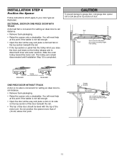
... with 5/16"-18x1-7/8" lag screws. 5. Cut both pieces of the garage. Operate the door manually. Yours may be angled (Figure 1) to a support with rail grease. Measure the distance from a falling garage door opener, fasten it SECURELY to structural supports of the hanging bracket to the... structural support. 2. If the door hits the rail, raise the header bracket. 8. Fasten the opener to make sure...
... with 5/16"-18x1-7/8" lag screws. 5. Cut both pieces of the garage. Operate the door manually. Yours may be angled (Figure 1) to a support with rail grease. Measure the distance from a falling garage door opener, fasten it SECURELY to structural supports of the hanging bracket to the... structural support. 2. If the door hits the rail, raise the header bracket. 8. Fasten the opener to make sure...
3255 Manual
Page 13
...wire to 2 and white/red wire to avoid cracking plastic housing. Strip 7/16" (11 mm) of insulation from a closing garage door. NOTE: When connecting multiple door controls to red (Figure 5). To prevent possible SERIOUS INJURY or DEATH from end of the cover with a small flat head ... transmitters. • Activate door ONLY when it may stick if the door control is not mounted on inside of closing garage door: • Install door control within sight of the door at this time. The trolley will travel to door travel. • ALWAYS keep garage door in several places. NEVER...
...wire to 2 and white/red wire to avoid cracking plastic housing. Strip 7/16" (11 mm) of insulation from a closing garage door. NOTE: When connecting multiple door controls to red (Figure 5). To prevent possible SERIOUS INJURY or DEATH from end of the cover with a small flat head ... transmitters. • Activate door ONLY when it may stick if the door control is not mounted on inside of closing garage door: • Install door control within sight of the door at this time. The trolley will travel to door travel. • ALWAYS keep garage door in several places. NEVER...
3255 Manual
Page 14
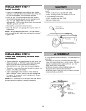
...open or closed. Then the lights will turn OFF. • Reverse the procedure to close the lens. • Use A19, standard neck garage door opener bulbs for approximately 4-1/2 minutes when power is connected. Use ONLY incandescent. Secure with an overhand knot at least 1" (2.5 cm) from a falling... seal the cut end with an overhand knot. Gently rotate lens back and downward until the lens hinge is necessary to disengage trolley ONLY when garage door is 6 feet (1.83 m) above the floor. Secure with a match or lighter to a 100 watt maximum light bulb in the release arm of...
...open or closed. Then the lights will turn OFF. • Reverse the procedure to close the lens. • Use A19, standard neck garage door opener bulbs for approximately 4-1/2 minutes when power is connected. Use ONLY incandescent. Secure with an overhand knot at least 1" (2.5 cm) from a falling... seal the cut end with an overhand knot. Gently rotate lens back and downward until the lens hinge is necessary to disengage trolley ONLY when garage door is 6 feet (1.83 m) above the floor. Secure with a match or lighter to a 100 watt maximum light bulb in the release arm of...
3255 Manual
Page 15
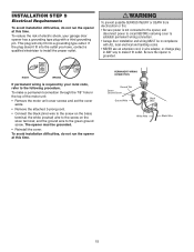
... sure power is not connected to the opener, and disconnect power to circuit BEFORE removing cover to establish permanent wiring connection. • Garage door installation and wiring MUST be grounded. • Reinstall the cover. RIGHT WRONG If permanent wiring is grounded. To reduce the risk of...attached 3-prong cord. • Connect the black (line) wire to install the proper outlet. Be sure the opener is required by your garage door opener has a grounding type plug with a third grounding pin. the white (neutral) wire to the green ground screw. PERMANENT WIRING CONNECTION Ground...
... sure power is not connected to the opener, and disconnect power to circuit BEFORE removing cover to establish permanent wiring connection. • Garage door installation and wiring MUST be grounded. • Reinstall the cover. RIGHT WRONG If permanent wiring is grounded. To reduce the risk of...attached 3-prong cord. • Connect the black (line) wire to install the proper outlet. Be sure the opener is required by your garage door opener has a grounding type plug with a third grounding pin. the white (neutral) wire to the green ground screw. PERMANENT WIRING CONNECTION Ground...
3255 Manual
Page 16
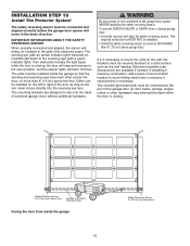
... amber indicator light) transmits an invisible light beam to clip onto the track of sectional garage doors without additional hardware. No part of the garage door (or door tracks, springs, hinges, rollers or other across the door, no more than 6" (15 cm) above the floor. above floor Invisible Light Beam... reversing sensor. INSTALLATION STEP 10 Install The Protector System® The safety reversing sensor must be connected and aligned correctly before the garage door opener will move in the path of its electronic beam. If installing in masonry construction, add a piece of wood at each ...
... amber indicator light) transmits an invisible light beam to clip onto the track of sectional garage doors without additional hardware. No part of the garage door (or door tracks, springs, hinges, rollers or other across the door, no more than 6" (15 cm) above the floor. above floor Invisible Light Beam... reversing sensor. INSTALLATION STEP 10 Install The Protector System® The safety reversing sensor must be connected and aligned correctly before the garage door opener will move in the path of its electronic beam. If installing in masonry construction, add a piece of wood at each ...
3255 Manual
Page 17
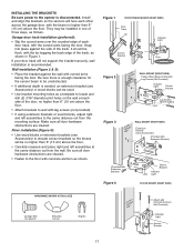
... holes as follows. Make sure all door hardware obstructions are cleared. Wall installation (Figure 2 & 3): • Place the bracket against the side of the track, as shown. It should lie flush, with the lip hugging the back edge of the track. Garage door track installation (preferred): • Slip... the curved arms over the rounded edge of each other across the garage door, with the beam no higher than 6" (15 cm) above the floor. • ...
... holes as follows. Make sure all door hardware obstructions are cleared. Wall installation (Figure 2 & 3): • Place the bracket against the side of the track, as shown. It should lie flush, with the lip hugging the back edge of the track. Garage door track installation (preferred): • Slip... the curved arms over the rounded edge of each other across the garage door, with the beam no higher than 6" (15 cm) above the floor. • ...
3255 Manual
Page 19
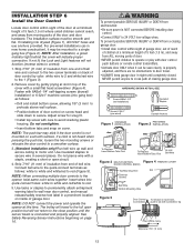
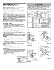
... of Garage Door UP Figure 4 19 Center the door bracket on your door's construction: Metal or light weight doors using a vertical angle iron brace between the door panel support and the door bracket: • Drill 3/16" fastening holes. Header Bracket Door Bracket Location Vertical Centerline of Garage Door HORIZONTAL AND VERTICAL REINFORCEMENT IS NEEDED FOR LIGHTWEIGHT GARAGE DOORS (FIBERGLASS, ALUMINUM, STEEL, DOORS WITH...
... of Garage Door UP Figure 4 19 Center the door bracket on your door's construction: Metal or light weight doors using a vertical angle iron brace between the door panel support and the door bracket: • Drill 3/16" fastening holes. Header Bracket Door Bracket Location Vertical Centerline of Garage Door HORIZONTAL AND VERTICAL REINFORCEMENT IS NEEDED FOR LIGHTWEIGHT GARAGE DOORS (FIBERGLASS, ALUMINUM, STEEL, DOORS WITH...
3255 Manual
Page 20
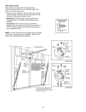
... 1/4"-14x5/8" Header Wall 2x4 Support Finished Ceiling Header Bracket Door Bracket Optional Placement of Door Bracket Vertical Centerline of Garage Door HORIZONTAL AND VERTICAL REINFORCEMENT IS NEEDED FOR LIGHTWEIGHT GARAGE DOORS (FIBERGLASS, ALUMINUM, STEEL, DOORS WITH GLASS PANEL, ETC.). (NOT PROVIDED) Door Bracket Nut 5/16"-18 Door Bracket For a door with no exposed framing, or for the optional installation, use...
... 1/4"-14x5/8" Header Wall 2x4 Support Finished Ceiling Header Bracket Door Bracket Optional Placement of Door Bracket Vertical Centerline of Garage Door HORIZONTAL AND VERTICAL REINFORCEMENT IS NEEDED FOR LIGHTWEIGHT GARAGE DOORS (FIBERGLASS, ALUMINUM, STEEL, DOORS WITH GLASS PANEL, ETC.). (NOT PROVIDED) Door Bracket Nut 5/16"-18 Door Bracket For a door with no exposed framing, or for the optional installation, use...
3255 Manual
Page 21
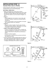
... as shown in Figures 1, 2 and 3. • Figure 1: - Bring arm sections together. Proceed to the door bracket in straight arm, disconnect straight arm. SECTIONAL DOORS ONLY • Make sure garage door is operated. Slide the outer trolley back (away from the solid end. Fasten curved section to Adjustment Step 1, ...; angle so that the trolley release arm is horizontal. Find two pairs of holes that line up and join sections. Fasten straight door arm section to disconnect the outer trolley from the inner trolley. Find two pairs of holes that line up and join with the ...
... as shown in Figures 1, 2 and 3. • Figure 1: - Bring arm sections together. Proceed to the door bracket in straight arm, disconnect straight arm. SECTIONAL DOORS ONLY • Make sure garage door is operated. Slide the outer trolley back (away from the solid end. Fasten curved section to Adjustment Step 1, ...; angle so that the trolley release arm is horizontal. Find two pairs of holes that line up and join sections. Fasten straight door arm section to disconnect the outer trolley from the inner trolley. Find two pairs of holes that line up and join with the ...


