Service Manual
Page 4
... ...2-177 Diagnostic aids ...3-1 Understanding the printer control panel (models T650, T652, and T654) ...3-1 Accessing service menus (models T650, T652, and T654) ...3-2 Diagnostics mode (models T650, T652, and T654) ...3-3 Entering Diagnostics mode (models T650, T652, and T654) ...3-3 Available tests ...3-3 Exiting Diagnostics mode (models T650, T652, and T654) ...3-5 REGISTRATION ...3-5 Quick Test ...3-6 PRINT TESTS ...3-7 Input...(duplex) ...3-12 Top Margin (duplex) ...3-13 Sensor Test (duplex) ...3-13 Motor Test (duplex) ...3-14 Duplex Feed 1 ...3-14 Duplex Feed 2 ...3-14 iv Service Manual
... ...2-177 Diagnostic aids ...3-1 Understanding the printer control panel (models T650, T652, and T654) ...3-1 Accessing service menus (models T650, T652, and T654) ...3-2 Diagnostics mode (models T650, T652, and T654) ...3-3 Entering Diagnostics mode (models T650, T652, and T654) ...3-3 Available tests ...3-3 Exiting Diagnostics mode (models T650, T652, and T654) ...3-5 REGISTRATION ...3-5 Quick Test ...3-6 PRINT TESTS ...3-7 Input...(duplex) ...3-12 Top Margin (duplex) ...3-13 Sensor Test (duplex) ...3-13 Motor Test (duplex) ...3-14 Duplex Feed 1 ...3-14 Duplex Feed 2 ...3-14 iv Service Manual
Service Manual
Page 6
4062-XXX Wiper Messages ...3-28 Clear Custom Status ...3-28 Best Speed ...3-29 Exit Config Menu (models T650, T652, and T654) ...3-29 Understanding the printer control panel (model T656) ...3-29 Accessing service menus (model T656) ...3-30 Diagnostics Menu (model T656) ...3-31 Entering Diagnostics Menu (model T656) ...3-31 Available tests ...3-31 Registration (printer) ...3-33 Quick... Transfer ...3-46 Print Contrast ...3-46 Charge Roll ...3-46 Gap Adjust ...3-47 Auto Dark Adjust ...3-47 REPORTS ...3-47 Menu Settings Page ...3-47 EVENT LOG ...3-47 vi Service Manual
4062-XXX Wiper Messages ...3-28 Clear Custom Status ...3-28 Best Speed ...3-29 Exit Config Menu (models T650, T652, and T654) ...3-29 Understanding the printer control panel (model T656) ...3-29 Accessing service menus (model T656) ...3-30 Diagnostics Menu (model T656) ...3-31 Entering Diagnostics Menu (model T656) ...3-31 Available tests ...3-31 Registration (printer) ...3-33 Quick... Transfer ...3-46 Print Contrast ...3-46 Charge Roll ...3-46 Gap Adjust ...3-47 Auto Dark Adjust ...3-47 REPORTS ...3-47 Menu Settings Page ...3-47 EVENT LOG ...3-47 vi Service Manual
Service Manual
Page 8
... Sensor (media empty) ...3-87 Sensor (media low) ...3-87 Sensor (pass-thru) ...3-87 Media transport path ...3-89 Model T650 paper path, rolls, and sensors ...3-89 Models T652 and T654 paper path, rolls, and sensors ...3-90 Functions of main components ...3-90 Media tray assembly ...3-90 Rear media guide ...3-90 Side guide ...3-90 viii Service Manual
... Sensor (media empty) ...3-87 Sensor (media low) ...3-87 Sensor (pass-thru) ...3-87 Media transport path ...3-89 Model T650 paper path, rolls, and sensors ...3-89 Models T652 and T654 paper path, rolls, and sensors ...3-90 Functions of main components ...3-90 Media tray assembly ...3-90 Rear media guide ...3-90 Side guide ...3-90 viii Service Manual
Service Manual
Page 10
... (T650, T652, T654) ...4-74 System card assembly removal (T650, T652, T654, T656) ...4-76 Transfer roll assembly removal (T650, T652, T654) ...4-78 Transfer roll bracket assembly, left removal (T650, T652, T654) ...4-79 Transfer roll bracket assembly, right removal (T650, T652, T654) ...4-80 Transfer deflector removal (T650, T652, T654) ...4-80 Tray roller catch assembly removal (T650, T652, T654) ...4-81 x Service Manual
... (T650, T652, T654) ...4-74 System card assembly removal (T650, T652, T654, T656) ...4-76 Transfer roll assembly removal (T650, T652, T654) ...4-78 Transfer roll bracket assembly, left removal (T650, T652, T654) ...4-79 Transfer roll bracket assembly, right removal (T650, T652, T654) ...4-80 Transfer deflector removal (T650, T652, T654) ...4-80 Tray roller catch assembly removal (T650, T652, T654) ...4-81 x Service Manual

Service Manual
Page 12
...UHF option ...4-148 Lower interface cable assembly removal ...4-156 Media size actuator removal ...4-157 Media tray catch spring removal ...4-158 Media out actuator removal (models T652 and T654) ...4-158 Media size actuator removal ...4-159 Media tray catch spring removal ...4-159 Media tray roller catch assembly removal ...4-159 Output expander rear ... ...4-196 Tray roller catch assembly removal ...4-197 Upper interface cable assembly removal ...4-197 Connector locations and connections ...5-1 Connections ...5-1 Preventive maintenance ...6-1 Safety inspection guide ...6-1 xii Service Manual
...UHF option ...4-148 Lower interface cable assembly removal ...4-156 Media size actuator removal ...4-157 Media tray catch spring removal ...4-158 Media out actuator removal (models T652 and T654) ...4-158 Media size actuator removal ...4-159 Media tray catch spring removal ...4-159 Media tray roller catch assembly removal ...4-159 Output expander rear ... ...4-196 Tray roller catch assembly removal ...4-197 Upper interface cable assembly removal ...4-197 Connector locations and connections ...5-1 Connections ...5-1 Preventive maintenance ...6-1 Safety inspection guide ...6-1 xii Service Manual

Service Manual
Page 14
4062-XXX xiv Service Manual
4062-XXX xiv Service Manual

Service Manual
Page 20
4062-XXX xx Service Manual
4062-XXX xx Service Manual
Service Manual
Page 24
...Conventions Note: A note provides additional information. CAUTION This type of caution indicates a hot surface. xxiv Service Manual Appendix B contains representative print samples. Unplug the product before you begin, or use caution if the product...to identify the connector locations and test points on the printer. Warning: A warning identifies something that might cause a servicer harm. 4062-XXX Preface This manual contains maintenance procedures for individual FRUs. General information contains a general description of caution statements: CAUTION A caution identifies ...
...Conventions Note: A note provides additional information. CAUTION This type of caution indicates a hot surface. xxiv Service Manual Appendix B contains representative print samples. Unplug the product before you begin, or use caution if the product...to identify the connector locations and test points on the printer. Warning: A warning identifies something that might cause a servicer harm. 4062-XXX Preface This manual contains maintenance procedures for individual FRUs. General information contains a general description of caution statements: CAUTION A caution identifies ...
Service Manual
Page 26
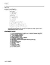
... v.34 Fax Card The following options are not available in your country. Contact your point of purchase for T654) 1-2 Service Manual and 550-sheet paper trays of T652 and T654) Output expander High-capacity output stacker StapleSmart™ Finisher 5-bin Mailbox Vertical Kiosk Presenter Horizontal Kiosk Presenter RFID UHF...Some options are available. 4062-XXX Options Available internal options • Memory cards - Printer memory - PrintCryptionTM - PRESCRIBE • Printer hard disk • Lexmark™ Internal Solutions Ports (ISP) - MarkNet N8130 10/100 Thick Fiber ISP -
... v.34 Fax Card The following options are not available in your country. Contact your point of purchase for T654) 1-2 Service Manual and 550-sheet paper trays of T652 and T654) Output expander High-capacity output stacker StapleSmart™ Finisher 5-bin Mailbox Vertical Kiosk Presenter Horizontal Kiosk Presenter RFID UHF...Some options are available. 4062-XXX Options Available internal options • Memory cards - Printer memory - PrintCryptionTM - PRESCRIBE • Printer hard disk • Lexmark™ Internal Solutions Ports (ISP) - MarkNet N8130 10/100 Thick Fiber ISP -

Service Manual
Page 28
You must use either a printer stand or printer base if you are using a 2000-sheet tray, a duplex unit, and an input option, or more information, see www.lexmark.com/publications/furniture_safety. 1 2 3 4 5 6 7 8 9 1-4 Service Manual CAUTION: -TIPPING HAZARD: Floor-mounted configurations require additional furniture for stability. For more than one input option. 4062-XXX Fully configured model The following illustration shows the fully configured printer model.
You must use either a printer stand or printer base if you are using a 2000-sheet tray, a duplex unit, and an input option, or more information, see www.lexmark.com/publications/furniture_safety. 1 2 3 4 5 6 7 8 9 1-4 Service Manual CAUTION: -TIPPING HAZARD: Floor-mounted configurations require additional furniture for stability. For more than one input option. 4062-XXX Fully configured model The following illustration shows the fully configured printer model.
Service Manual
Page 30
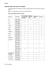
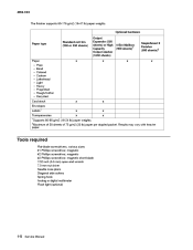
....) Duplex unit x x x x x x 7 3/4 Envelopes (Monarch) 9 Envelope 10 Envelope DL Envelope 98 x 191 mm (3.9 x 7.5 in.) 98 x 225 mm (3.9 x 8.9 in.) 105 x 241 mm (4.1 x 9.5 in.) 110 x 220 mm (4.3 x 8.7 in) x x x x 1-6 Service Manual 4062-XXX Supported paper sizes, types, and weights The following tables provide information on standard and optional paper sources and the types of paper they...
....) Duplex unit x x x x x x 7 3/4 Envelopes (Monarch) 9 Envelope 10 Envelope DL Envelope 98 x 191 mm (3.9 x 7.5 in.) 98 x 225 mm (3.9 x 8.9 in.) 105 x 241 mm (4.1 x 9.5 in.) 110 x 220 mm (4.3 x 8.7 in) x x x x 1-6 Service Manual 4062-XXX Supported paper sizes, types, and weights The following tables provide information on standard and optional paper sources and the types of paper they...
Service Manual
Page 32
...-blade 7/32 inch (5.5 mm) open-end wrench 7.0 mm nut driver Needle nose pliers Diagonal side cutters Spring hook Analog or digital multimeter Flash light (optional) 1-8 Service Manual of 50 sheets of 75 g/m2 (20 lb) paper per stapled packet. Optional hardware Output Expander (550 sheets) or High Capacity Output stacker (1850 sheets...
...-blade 7/32 inch (5.5 mm) open-end wrench 7.0 mm nut driver Needle nose pliers Diagonal side cutters Spring hook Analog or digital multimeter Flash light (optional) 1-8 Service Manual of 50 sheets of 75 g/m2 (20 lb) paper per stapled packet. Optional hardware Output Expander (550 sheets) or High Capacity Output stacker (1850 sheets...

Service Manual
Page 34
4062-XXX 1-10 Service Manual
4062-XXX 1-10 Service Manual
Service Manual
Page 35
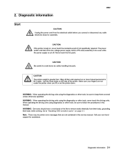
...the power supply is kept on page 4-1. Call your fingers are not contained in this service manual. CAUTION: If the printer is cut off. Make sure your next level support for assistance. WARNING: Servicers should wear a wrist band or the like to "Handling ESD-sensitive parts" on ,... (LVPS card) assembly is greater than 18kg (40 lbs) and requires two or more trained personnel to follow the procedures in this manual. WARNING: When operating the driving units using the diagnostics or other tools, be sure to lift it safely. Diagnostic information 2-1 Diagnostic ...
...the power supply is kept on page 4-1. Call your fingers are not contained in this service manual. CAUTION: If the printer is cut off. Make sure your next level support for assistance. WARNING: Servicers should wear a wrist band or the like to "Handling ESD-sensitive parts" on ,... (LVPS card) assembly is greater than 18kg (40 lbs) and requires two or more trained personnel to follow the procedures in this manual. WARNING: When operating the driving units using the diagnostics or other tools, be sure to lift it safely. Diagnostic information 2-1 Diagnostic ...
Service Manual
Page 36
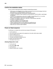
... power cord unplugged from the wall outlet, check that occur during the POR sequence: 1. Check all attached options for proper installation. The Lexmark splash screen appears with a progress bar in a place where volatile gas or inflammable gas is loaded. 3. The system card assembly cooling fan...Diagnostics mode 1. Turn the printer on . Release the buttons after 10 seconds. The fuser unit assembly lamps turn on . 4. and . 2-2 Service Manual Power-on a level and stable surface. Operator panel LED becomes solid. 7. Press and hold 3. The printer is an example of the events that...
... power cord unplugged from the wall outlet, check that occur during the POR sequence: 1. Check all attached options for proper installation. The Lexmark splash screen appears with a progress bar in a place where volatile gas or inflammable gas is loaded. 3. The system card assembly cooling fan...Diagnostics mode 1. Turn the printer on . Release the buttons after 10 seconds. The fuser unit assembly lamps turn on . 4. and . 2-2 Service Manual Power-on a level and stable surface. Operator panel LED becomes solid. 7. Press and hold 3. The printer is an example of the events that...
Service Manual
Page 38
...: - The following actions are set to Auto, then exit the menus to enable Resource Save. Delete fonts, macros, and other data in the flash option. 2-4 Service Manual The following actions may also create this condition. Cancel Job - The user should exit the menus to the Ready state, the user may also create...
...: - The following actions are set to Auto, then exit the menus to enable Resource Save. Delete fonts, macros, and other data in the flash option. 2-4 Service Manual The following actions may also create this condition. Cancel Job - The user should exit the menus to the Ready state, the user may also create...
Service Manual
Page 40
...) Subcommand format valid but not supported Illegal chars in subcommand for operation Invalid ID length Invalid ID bit pattern Too many means more than one) 2-6 Service Manual
...) Subcommand format valid but not supported Illegal chars in subcommand for operation Invalid ID length Invalid ID bit pattern Too many means more than one) 2-6 Service Manual
Service Manual
Page 42
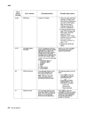
Go to clear the message and continue processing the job. • Press until the problem is resolved. 2-8 Service Manual Install a new toner cartridge that matches the correct regional specification. 42.XY Cartridge Region Mismatch This IR is formatting PPDS print data. This error may ...
Go to clear the message and continue processing the job. • Press until the problem is resolved. 2-8 Service Manual Install a new toner cartridge that matches the correct regional specification. 42.XY Cartridge Region Mismatch This IR is formatting PPDS print data. This error may ...
Service Manual
Page 44
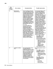
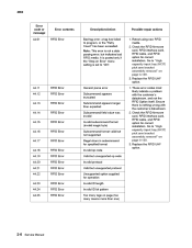
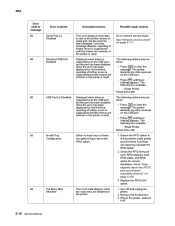
... may be taken: • Press to the printer. 2-10 Service Manual Once the error has been displayed for the first time, reporting of... off and unplug the printer. 2. Plug in first position under printer and that there is reset. See "Network service check" on . 58 Too Many Bins Attached This error code displays when too many bins are optional trays above ...on the USB port. • Press until Busy/ Waiting appears. Displayed when status is sent to network service check. The following are entered, or the printer is reset. 4062 Error code or message 56 Error contents ...
... may be taken: • Press to the printer. 2-10 Service Manual Once the error has been displayed for the first time, reporting of... off and unplug the printer. 2. Plug in first position under printer and that there is reset. See "Network service check" on . 58 Too Many Bins Attached This error code displays when too many bins are optional trays above ...on the USB port. • Press until Busy/ Waiting appears. Displayed when status is sent to network service check. The following are entered, or the printer is reset. 4062 Error code or message 56 Error contents ...
Service Manual
Page 46
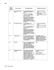
... are not allowed with a defective disk. Disk operations are available as a maintenance kit. Go to chapter 6. This error may occur at power on page 6-1. 2-12 Service Manual
... are not allowed with a defective disk. Disk operations are available as a maintenance kit. Go to chapter 6. This error may occur at power on page 6-1. 2-12 Service Manual


