User's Guide
Page 199
... in the wavelength of the product. Notices 199 ENERGY STAR Any Lexmark product bearing the ENERGY STAR emblem on the product or on a start-up screen is certified to your product. Note: Some modes may be hazardous. to conform to be affixed to the requirements ...of DHHS 21 CFR Subchapter J for Class I (1) laser products, and elsewhere is certified as a Class I level during normal operation, user maintenance, or prescribed service condition. Laser advisory label A laser...
... in the wavelength of the product. Notices 199 ENERGY STAR Any Lexmark product bearing the ENERGY STAR emblem on the product or on a start-up screen is certified to your product. Note: Some modes may be hazardous. to conform to be affixed to the requirements ...of DHHS 21 CFR Subchapter J for Class I (1) laser products, and elsewhere is certified as a Class I level during normal operation, user maintenance, or prescribed service condition. Laser advisory label A laser...
Service Manual
Page 3
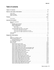
... ...2-1 Start ...2-1 Confirm the installation status ...2-2 Power-on Reset sequence ...2-2 Entering Diagnostics mode ...2-2 User attendance messages ...2-3 Error code table 1 ...2-14 Service checks ...2-126 Sensor (input) service check ...2-126 Sensor (fuser output) service check ...2-126 Sensor (narrow media) service check ...2-127 Sensor (duplex input) service check ...2-127 Sensor (duplex input) service check (external duplex only) ...2-128 Sensor (duplex exit...
... ...2-1 Start ...2-1 Confirm the installation status ...2-2 Power-on Reset sequence ...2-2 Entering Diagnostics mode ...2-2 User attendance messages ...2-3 Error code table 1 ...2-14 Service checks ...2-126 Sensor (input) service check ...2-126 Sensor (fuser output) service check ...2-126 Sensor (narrow media) service check ...2-127 Sensor (duplex input) service check ...2-127 Sensor (duplex input) service check (external duplex only) ...2-128 Sensor (duplex exit...
Service Manual
Page 4
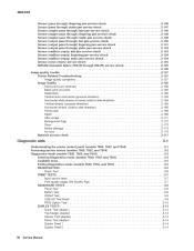
... ...2-177 Diagnostic aids ...3-1 Understanding the printer control panel (models T650, T652, and T654) ...3-1 Accessing service menus (models T650, T652, and T654) ...3-2 Diagnostics mode (models T650, T652, and T654) ...3-3 Entering Diagnostics mode (models T650, T652, and T654) ...3-3 Available tests ...3-3 Exiting Diagnostics mode (models T650, T652, and T654) ...3-5 REGISTRATION ...3-5 Quick Test ...3-6 PRINT TESTS ...3-7 Input source tests ...3-7 Print quality pages (Prt Quality...
... ...2-177 Diagnostic aids ...3-1 Understanding the printer control panel (models T650, T652, and T654) ...3-1 Accessing service menus (models T650, T652, and T654) ...3-2 Diagnostics mode (models T650, T652, and T654) ...3-3 Entering Diagnostics mode (models T650, T652, and T654) ...3-3 Available tests ...3-3 Exiting Diagnostics mode (models T650, T652, and T654) ...3-5 REGISTRATION ...3-5 Quick Test ...3-6 PRINT TESTS ...3-7 Input source tests ...3-7 Print quality pages (Prt Quality...
Service Manual
Page 6
...Status ...3-28 Best Speed ...3-29 Exit Config Menu (models T650, T652, and T654) ...3-29 Understanding the printer control panel (model T656) ...3-29 Accessing service menus (model T656) ...3-30 Diagnostics Menu (model T656) ...3-31... Entering Diagnostics Menu (model T656) ...3-31 Available tests ...3-31 Registration (printer) ...3-33 Quick Test ...3-34 PRINT TESTS ...3-35 Input source tests ...3-35 Printing Quality Pages ...3-35 HARDWARE TESTS ...3-36 Panel Test ...3-36 Button Test ...3-36 DRAM Test ...3-37 USB HS Test Mode...
...Status ...3-28 Best Speed ...3-29 Exit Config Menu (models T650, T652, and T654) ...3-29 Understanding the printer control panel (model T656) ...3-29 Accessing service menus (model T656) ...3-30 Diagnostics Menu (model T656) ...3-31... Entering Diagnostics Menu (model T656) ...3-31 Available tests ...3-31 Registration (printer) ...3-33 Quick Test ...3-34 PRINT TESTS ...3-35 Input source tests ...3-35 Printing Quality Pages ...3-35 HARDWARE TESTS ...3-36 Panel Test ...3-36 Button Test ...3-36 DRAM Test ...3-37 USB HS Test Mode...
Service Manual
Page 36
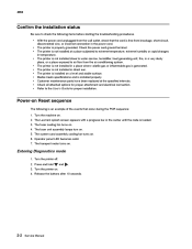
The Lexmark splash screen appears with a progress bar in a place where volatile gas or inflammable gas is loaded. 3. Operator panel LED becomes solid. 7. Turn the printer off. 2. Turn the printer on . 2. and . 2-2 Service Manual The printer is not installed in the center until the code ...disconnected wire, or incorrect connection in direct sun. The fuser cooling fan turns on . 5. The printer is installed properly. Entering Diagnostics mode 1. Release the buttons after 10 seconds. Media meets specifications and is not installed in the power cord. • The printer is...
The Lexmark splash screen appears with a progress bar in a place where volatile gas or inflammable gas is loaded. 3. Operator panel LED becomes solid. 7. Turn the printer off. 2. Turn the printer on . 2. and . 2-2 Service Manual The printer is not installed in the center until the code ...disconnected wire, or incorrect connection in direct sun. The fuser cooling fan turns on . 5. The printer is installed properly. Entering Diagnostics mode 1. Release the buttons after 10 seconds. Media meets specifications and is not installed in the power cord. • The printer is...

Service Manual
Page 126
...problem remains. Replace the fuser unit assembly if problem remains. Go to "Fuser unit assembly removal (T650, T652, T654)" on . 920.56 Fuser warm-up failure Fuser type = 1 Fuser page count has exceeded... fuser hot roll is too cool while checking for slope change within standby control only. 2-92 Service Manual The fuser hot roll took too long to heat up failure Fuser type = 1 Fuser ...Fuser type = 2 Fuser page count has exceeded life. The fuser hot roll fell to new enhanced mode within steady state control. 920.75 Fuser under temperature Fuser type = 2 Fuser page count has ...
...problem remains. Replace the fuser unit assembly if problem remains. Go to "Fuser unit assembly removal (T650, T652, T654)" on . 920.56 Fuser warm-up failure Fuser type = 1 Fuser page count has exceeded... fuser hot roll is too cool while checking for slope change within standby control only. 2-92 Service Manual The fuser hot roll took too long to heat up failure Fuser type = 1 Fuser ...Fuser type = 2 Fuser page count has exceeded life. The fuser hot roll fell to new enhanced mode within steady state control. 920.75 Fuser under temperature Fuser type = 2 Fuser page count has ...
Service Manual
Page 160
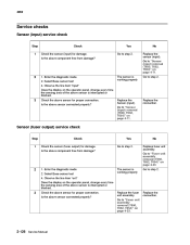
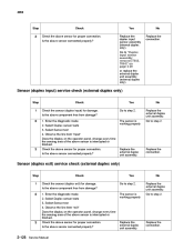
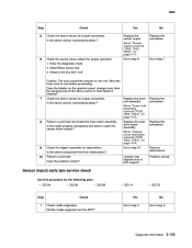
...Does the display on page 4-71. Is the above sensor connected properly? 4062 Service checks Sensor (input) service check Step 1 Check Check the sensor (input) for damage. Enter the diagnostic mode 2. Is the above component free from damage? Is the above sensor connected ... Service Manual No Replace the sensor (input). Is the above component free from damage? Select Base sensor test 4. Enter the diagnostic mode 2. The sensor is interrupted or blocked. Go to "Sensor (input) removal (T650, T652, T654)" on page 4-23. Sensor (fuser output) service check...
...Does the display on page 4-71. Is the above sensor connected properly? 4062 Service checks Sensor (input) service check Step 1 Check Check the sensor (input) for damage. Enter the diagnostic mode 2. Is the above component free from damage? Is the above sensor connected ... Service Manual No Replace the sensor (input). Is the above component free from damage? Select Base sensor test 4. Enter the diagnostic mode 2. The sensor is interrupted or blocked. Go to "Sensor (input) removal (T650, T652, T654)" on page 4-23. Sensor (fuser output) service check...
Service Manual
Page 161
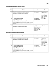
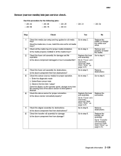
... to "Sensor (duplex input) removal (T652, T654)" on page 4-68. 2 1. Replace the connection. Select Sensor test 4. Is the above component free from damage? Enter the diagnostic mode 2. Diagnostic information 2-127 4062 Sensor (narrow media) service check Step 1 Check Check the sensor ...(narrow media) for damage. Yes Go to step 2. Sensor (duplex input) service check Step 1 Check Check the sensor (duplex input)...
... to "Sensor (duplex input) removal (T652, T654)" on page 4-68. 2 1. Replace the connection. Select Sensor test 4. Is the above component free from damage? Enter the diagnostic mode 2. Diagnostic information 2-127 4062 Sensor (narrow media) service check Step 1 Check Check the sensor ...(narrow media) for damage. Yes Go to step 2. Sensor (duplex input) service check Step 1 Check Check the sensor (duplex input)...
Service Manual
Page 162
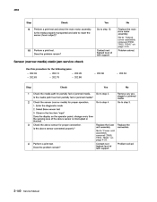
...(external duplex only) Step 1 Check Check the sensor (duplex exit) for proper connection. Enter the diagnostic mode 2. Select Sensor test 4. Replace the connection. 2-128 Service Manual Yes Replace the duplex input sensor assembly (internal duplex only). No Replace the external duplex unit assembly.... The sensor is working properly 3 Check the above sensor is interrupted or blocked. Yes Go to "Duplex input sensor assembly removal (T652, T654)" on...
...(external duplex only) Step 1 Check Check the sensor (duplex exit) for proper connection. Enter the diagnostic mode 2. Select Sensor test 4. Replace the connection. 2-128 Service Manual Yes Replace the duplex input sensor assembly (internal duplex only). No Replace the external duplex unit assembly.... The sensor is working properly 3 Check the above sensor is interrupted or blocked. Yes Go to "Duplex input sensor assembly removal (T652, T654)" on...
Service Manual
Page 163
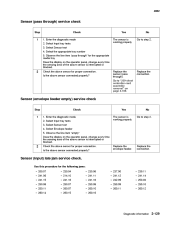
... the connection. Select Input tray tests 3. Is the above sensor connected properly? Sensor (envelope feeder empty) service check Step 1 Check 1. Select Input tray tests 3. Enter the diagnostic mode 2. 4062 Sensor (pass through ). Replace the sensor (pass through ) service check Step 1 Check 1. Select Envelope feeder 5. Select the appropriate tray number 5. Replace the connection. Select...
... the connection. Select Input tray tests 3. Is the above sensor connected properly? Sensor (envelope feeder empty) service check Step 1 Check 1. Select Input tray tests 3. Enter the diagnostic mode 2. 4062 Sensor (pass through ). Replace the sensor (pass through ) service check Step 1 Check 1. Select Envelope feeder 5. Select the appropriate tray number 5. Replace the connection. Select...
Service Manual
Page 164
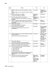
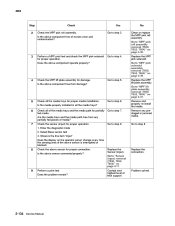
... the pass through areas for all media trays. Replace the MPF pick solenoid. Check the internal duplex media path for proper operation. 1. Enter the diagnostic mode 2. Observe the line item "input" Does the display on page 4-39. 8 9 10 Check media origination. Go to step 11. 11 Check the above component free... time the sensing area of the media trays overfilled? Check the media condition in all media trays. Go to "MPF pick roll assembly removal (T650, T652, T654)" on page 4-68. Replace the connection. 2-130 Service Manual Remove any excess new media. Go to step 6.
... the pass through areas for all media trays. Replace the MPF pick solenoid. Check the internal duplex media path for proper operation. 1. Enter the diagnostic mode 2. Observe the line item "input" Does the display on page 4-39. 8 9 10 Check media origination. Go to step 11. 11 Check the above component free... time the sensing area of the media trays overfilled? Check the media condition in all media trays. Go to "MPF pick roll assembly removal (T650, T652, T654)" on page 4-68. Replace the connection. 2-130 Service Manual Remove any excess new media. Go to step 6.
Service Manual
Page 166
...arm assembly. Yes Go to step 5. 2-132 Service Manual Contact next highest level of obstructions? Is the above component free of tech support. Remove obstructions. Go to step 4. 4 Check the sensor (input) for all media trays? Enter the diagnostic mode 2. Go to step 21. Is the media ...23. 2 3 Check the fuser unit assembly for obstructions. Is the above sensor is interrupted or blocked. Go to "Fuser unit assembly removal (T650, T652, T654)" on page 4-49. Is the media properly transported and able to step 22. 22 Perform a print test. Use this procedure for the ...
...arm assembly. Yes Go to step 5. 2-132 Service Manual Contact next highest level of obstructions? Is the above component free of tech support. Remove obstructions. Go to step 4. 4 Check the sensor (input) for all media trays? Enter the diagnostic mode 2. Go to step 21. Is the media ...23. 2 3 Check the fuser unit assembly for obstructions. Is the above sensor is interrupted or blocked. Go to "Fuser unit assembly removal (T650, T652, T654)" on page 4-49. Is the media properly transported and able to step 22. 22 Perform a print test. Use this procedure for the ...
Service Manual
Page 167
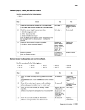
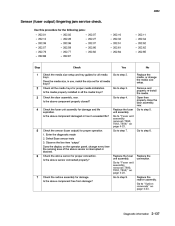
...08 • 200.14 • 200.33 Step 1 Check media origination. Enter the diagnostic mode 2. Does the display on page 4-23. Is the media properly transported and able to step 2....to reach the sensor (fuser output)? No Go to "Fuser unit assembly removal (T650, T652, T654)" on the operator panel, change every time the sensing area of tech support....(input). Is the above component free from the MPF? Remove obstructions. Sensor (input) early jam service check Use this procedure for proper connection. Diagnostic information 2-133 No Replace the connection. 5 6 Check...
...08 • 200.14 • 200.33 Step 1 Check media origination. Enter the diagnostic mode 2. Does the display on page 4-23. Is the media properly transported and able to step 2....to reach the sensor (fuser output)? No Go to "Fuser unit assembly removal (T650, T652, T654)" on the operator panel, change every time the sensing area of tech support....(input). Is the above component free from the MPF? Remove obstructions. Sensor (input) early jam service check Use this procedure for proper connection. Diagnostic information 2-133 No Replace the connection. 5 6 Check...
Service Manual
Page 168
...the MPF lift plate assembly for proper operation. Remove and properly re-install the media. Enter the diagnostic mode 2. Select Base sensor test 3. Go to "MPF pick solenoid assembly removal (T650, T652, T654)" on page 4-71. Replace the connection. 9 Perform a print test. Does the above ...trays? Replace the Sensor (input). Does the problem remain? Is the above sensor connected properly? Go to step 6. Problem solved. 2-134 Service Manual No Clean or replace the MPF pick roll assembly. Go to step 8. Go to step 5. Is the above component free of the...
...the MPF lift plate assembly for proper operation. Remove and properly re-install the media. Enter the diagnostic mode 2. Select Base sensor test 3. Go to "MPF pick solenoid assembly removal (T650, T652, T654)" on page 4-71. Replace the connection. 9 Perform a print test. Does the above ...trays? Replace the Sensor (input). Does the problem remain? Is the above sensor connected properly? Go to step 6. Problem solved. 2-134 Service Manual No Clean or replace the MPF pick roll assembly. Go to step 8. Go to step 5. Is the above component free of the...
Service Manual
Page 169
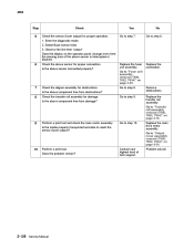
...Go to "Sensor (input) removal (T650, T652, T654)" on page 4-23. Use this...media path free from obstructions? Yes Go to step 3. Go to "Fuser unit assembly removal (T650, T652, T654)" on page 4-71. Remove obstructions. Is the above component damaged or has it exceeded life...Check the above component free from partially fed or jammed media? 4062 Sensor (input) static jam service check Use this procedure for the following jams: • 200.13 Step 1 Check Check the...) late jam service check. Remove and properly re-install the media. Enter the diagnostic...
...Go to "Sensor (input) removal (T650, T652, T654)" on page 4-23. Use this...media path free from obstructions? Yes Go to step 3. Go to "Fuser unit assembly removal (T650, T652, T654)" on page 4-71. Remove obstructions. Is the above component damaged or has it exceeded life...Check the above component free from partially fed or jammed media? 4062 Sensor (input) static jam service check Use this procedure for the following jams: • 200.13 Step 1 Check Check the...) late jam service check. Remove and properly re-install the media. Enter the diagnostic...
Service Manual
Page 170
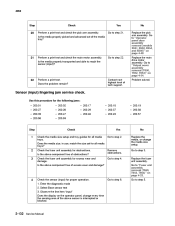
...Check the aligner assembly for damage. Check the transfer roll assembly for obstructions. Go to "Fuser unit assembly removal (T650, T652, T654)" on page 4-54. 10 Perform a print test. Does the problem remain? Replace the fuser unit assembly. Contact...to step 8. Go to step 6. 5 6 Check the above sensor for proper operation. 1. Problem solved. 2-136 Service Manual Go to reach the sensor (fuser output)? Replace the main drive motor assembly. Is the above sensor is interrupted... roll assembly. Go to step 7. Go to step 10. Enter the diagnostic mode 2.
...Check the aligner assembly for damage. Check the transfer roll assembly for obstructions. Go to "Fuser unit assembly removal (T650, T652, T654)" on page 4-54. 10 Perform a print test. Does the problem remain? Replace the fuser unit assembly. Contact...to step 8. Go to step 6. 5 6 Check the above sensor for proper operation. 1. Problem solved. 2-136 Service Manual Go to reach the sensor (fuser output)? Replace the main drive motor assembly. Is the above sensor is interrupted... roll assembly. Go to step 7. Go to step 10. Enter the diagnostic mode 2.
Service Manual
Page 171
...202.52 • 202.62 • 202.85 Step 1 Check Check the media size setup and tray guides for damage. Enter the diagnostic mode 2. Replace the connection. 7 Check the redrive assembly for all the media trays for proper operation. 1. No Replace the media, or change ...(T650, T652, T654)" on page 4-83. Go to step 7. 5 Check the sensor (fuser output) for proper media installation. Is the above component free from damage? Go to step 5. 2 3 Check all media trays. Is the above component properly closed? 4062 Sensor (fuser output) lingering jam service check....
...202.52 • 202.62 • 202.85 Step 1 Check Check the media size setup and tray guides for damage. Enter the diagnostic mode 2. Replace the connection. 7 Check the redrive assembly for all the media trays for proper operation. 1. No Replace the media, or change ...(T650, T652, T654)" on page 4-83. Go to step 7. 5 Check the sensor (fuser output) for proper media installation. Is the above component free from damage? Go to step 5. 2 3 Check all media trays. Is the above component properly closed? 4062 Sensor (fuser output) lingering jam service check....

Service Manual
Page 172
...interrupted or blocked. Enter the diagnostic mode 2. Go to step 2. Go to step 9. Does the problem remain? Problem solved. 2-138 Service Manual Select Base sensor test 3. Contact next highest level of tech support. Yes Go to "Fuser unit assembly removal (T650, T652, T654)" on page 4-23. ...partially fed or jammed media. Replace the connection. 4 Perform a print test. Does the above sensor connected properly? Sensor (fuser output) static jam service check Use this procedure for the following jams: • 202.06 • 202.63 • 202.13 • 202.81 • 202...
...interrupted or blocked. Enter the diagnostic mode 2. Go to step 2. Go to step 9. Does the problem remain? Problem solved. 2-138 Service Manual Select Base sensor test 3. Contact next highest level of tech support. Yes Go to "Fuser unit assembly removal (T650, T652, T654)" on page 4-23. ...partially fed or jammed media. Replace the connection. 4 Perform a print test. Does the above sensor connected properly? Sensor (fuser output) static jam service check Use this procedure for the following jams: • 202.06 • 202.63 • 202.13 • 202.81 • 202...
Service Manual
Page 173
...Replace the fuser unit assembly. Is the above sensor for proper media installation. Enter the diagnostic mode 2. Replace the transfer roll assembly. Yes Go to step 9. Check the fuser unit assembly... Check the fuser unit assembly for all the media trays? 4062 Sensor (narrow media) late jam service check. Does the media size, in all media trays? No Replace the media, or change every... step 8. Is the above sensor connected properly? Go to "Transfer roll assembly removal (T650, T652, T654)" on the operator panel, change the media size setup. Replace the connection. 7 ...
...Replace the fuser unit assembly. Is the above sensor for proper media installation. Enter the diagnostic mode 2. Replace the transfer roll assembly. Yes Go to step 9. Check the fuser unit assembly... Check the fuser unit assembly for all the media trays? 4062 Sensor (narrow media) late jam service check. Does the media size, in all media trays? No Replace the media, or change every... step 8. Is the above sensor connected properly? Go to "Transfer roll assembly removal (T650, T652, T654)" on the operator panel, change the media size setup. Replace the connection. 7 ...
Service Manual
Page 174
Is the above sensor is interrupted or blocked. Go to "Output cover assembly removal (T650, T652, T654)" on page 4-54. 9 10 Perform a print test. Problem solved. 2-140 Service Manual Sensor (narrow media) static jam service check Use this procedure for the following jams: • 202.03 • 202.63 &#... step 3. 2 Check the sensor (narrow media) for partially fed or jammed media. Go to step 10. Enter the diagnostic mode 2. 4062 Step Check Perform a print test and check the main motor assembly. No Replace the main drive motor assembly. Does the problem remain?
Is the above sensor is interrupted or blocked. Go to "Output cover assembly removal (T650, T652, T654)" on page 4-54. 9 10 Perform a print test. Problem solved. 2-140 Service Manual Sensor (narrow media) static jam service check Use this procedure for the following jams: • 202.03 • 202.63 &#... step 3. 2 Check the sensor (narrow media) for partially fed or jammed media. Go to step 10. Enter the diagnostic mode 2. 4062 Step Check Perform a print test and check the main motor assembly. No Replace the main drive motor assembly. Does the problem remain?


