
Hardware Maintenance Manual
Page 4
..., DC-in connector cable, and ExpressCard slot assembly 106 2010 LCD bezel assembly 108 2020 LED board 109 2030 Integrated camera 110 2040 LCD panel and LCD cable 111 2050 Camera cable 113 2060 Wireless LAN antenna assembly or wireless LAN/WAN antenna assembly 116 2070 Hinges and LCD rear cover assembly...
..., DC-in connector cable, and ExpressCard slot assembly 106 2010 LCD bezel assembly 108 2020 LED board 109 2030 Integrated camera 110 2040 LCD panel and LCD cable 111 2050 Camera cable 113 2060 Wireless LAN antenna assembly or wireless LAN/WAN antenna assembly 116 2070 Hinges and LCD rear cover assembly...

Hardware Maintenance Manual
Page 63
...off the computer), change the settings. Fn+F5 Fn+F6 Fn+F7 Notes: To use this combination of the keys, ThinkPad PM device driver must have been installed on the computer. Fn+F4 Notes: To use this combination of the keys... display and external monitor (extended desktop function) © Copyright Lenovo 2010, 2012 57 For Windows 7: Switch between the computer display and an external monitor. Chapter 6. Note: The camera settings area only appears if the computer has an integrated camera. Fn key combinations Key combination Description Fn+F1 Reserved.
...off the computer), change the settings. Fn+F5 Fn+F6 Fn+F7 Notes: To use this combination of the keys, ThinkPad PM device driver must have been installed on the computer. Fn+F4 Notes: To use this combination of the keys... display and external monitor (extended desktop function) © Copyright Lenovo 2010, 2012 57 For Windows 7: Switch between the computer display and an external monitor. Chapter 6. Note: The camera settings area only appears if the computer has an integrated camera. Fn key combinations Key combination Description Fn+F1 Reserved.

Hardware Maintenance Manual
Page 116
Removal steps of LED board 1 2 1 3 Step 1 Screw (quantity) M2 × 3.5 mm, flat-head, nylon-coated (2) Color Silver When installing: Make sure that the connector is attached firmly. 2030 Integrated camera For access, remove these FRUs in order: • "1010 Battery pack" on page 66 • "2010 LCD bezel assembly" on page 108 Torque 0.181 Nm (1.85 kgfcm) 110 Hardware Maintenance Manual
Removal steps of LED board 1 2 1 3 Step 1 Screw (quantity) M2 × 3.5 mm, flat-head, nylon-coated (2) Color Silver When installing: Make sure that the connector is attached firmly. 2030 Integrated camera For access, remove these FRUs in order: • "1010 Battery pack" on page 66 • "2010 LCD bezel assembly" on page 108 Torque 0.181 Nm (1.85 kgfcm) 110 Hardware Maintenance Manual

Hardware Maintenance Manual
Page 117
Removing and replacing a FRU 111 Removal steps of integrated camera 1 3 2 Step 1 Screw (quantity) M2 × 3.5 mm, flat-head, nylon-coated (1) Color Silver Torque 0.181 Nm (1.85 kgfcm) When installing: Make sure that the connector is ... • "1160 LCD unit" on page 91 • "2010 LCD bezel assembly" on page 108 • "2020 LED board" on page 109 • "2030 Integrated camera" on page 110 Chapter 8.
Removing and replacing a FRU 111 Removal steps of integrated camera 1 3 2 Step 1 Screw (quantity) M2 × 3.5 mm, flat-head, nylon-coated (1) Color Silver Torque 0.181 Nm (1.85 kgfcm) When installing: Make sure that the connector is ... • "1160 LCD unit" on page 91 • "2010 LCD bezel assembly" on page 108 • "2020 LED board" on page 109 • "2030 Integrated camera" on page 110 Chapter 8.

Hardware Maintenance Manual
Page 119
... 0.181 Nm (1.85 kgfcm) When installing: When attaching the LCD panel to the panel. 9 8 When installing: Make sure that the connector is attached firmly. 2050 Camera cable For access, remove these FRUs in order: • "1010 Battery pack" on page 66 • "1020 ExpressCard blank bezel" on page 67 • "1050... • "1160 LCD unit" on page 91 • "2010 LCD bezel assembly" on page 108 • "2020 LED board" on page 109 • "2030 Integrated camera" on page 110 • "2040 LCD panel and LCD cable" on page 111 Chapter 8.
... 0.181 Nm (1.85 kgfcm) When installing: When attaching the LCD panel to the panel. 9 8 When installing: Make sure that the connector is attached firmly. 2050 Camera cable For access, remove these FRUs in order: • "1010 Battery pack" on page 66 • "1020 ExpressCard blank bezel" on page 67 • "1050... • "1160 LCD unit" on page 91 • "2010 LCD bezel assembly" on page 108 • "2020 LED board" on page 109 • "2030 Integrated camera" on page 110 • "2040 LCD panel and LCD cable" on page 111 Chapter 8.
Hardware Maintenance Manual
Page 120
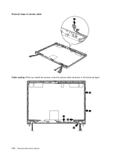
Removal steps of camera cable 1 Cable routing: When you install the camera, route the camera cable as shown in the following figure. 2 2 2 2 2 114 Hardware Maintenance Manual
Removal steps of camera cable 1 Cable routing: When you install the camera, route the camera cable as shown in the following figure. 2 2 2 2 2 114 Hardware Maintenance Manual

Hardware Maintenance Manual
Page 121
Otherwise the panel will crack. For models without camera: Make sure that the LED connector is installed in the proper position as shown in the following figure. 2 2 2 2 2 Note: Tape up the camera connector as shown in the following figure and make sure that the LED cable is not placed underneath the LCD panel. Chapter 8. Removing and replacing a FRU 115 Note: Make sure that it is pasted on the LCD rear cover and parallel with the antenna module.
Otherwise the panel will crack. For models without camera: Make sure that the LED connector is installed in the proper position as shown in the following figure. 2 2 2 2 2 Note: Tape up the camera connector as shown in the following figure and make sure that the LED cable is not placed underneath the LCD panel. Chapter 8. Removing and replacing a FRU 115 Note: Make sure that it is pasted on the LCD rear cover and parallel with the antenna module.

Hardware Maintenance Manual
Page 122
...; "2010 LCD bezel assembly" on page 108 • "2020 LED board" on page 109 • "2030 Integrated camera" on page 110 • "2040 LCD panel and LCD cable" on page 111 • "2050 Camera cable" on page 113 Removal steps of wireless LAN antenna assembly or wireless LAN/WAN antenna assembly 2 2 2 22...
...; "2010 LCD bezel assembly" on page 108 • "2020 LED board" on page 109 • "2030 Integrated camera" on page 110 • "2040 LCD panel and LCD cable" on page 111 • "2050 Camera cable" on page 113 Removal steps of wireless LAN antenna assembly or wireless LAN/WAN antenna assembly 2 2 2 22...

Hardware Maintenance Manual
Page 124
...; "2010 LCD bezel assembly" on page 108 • "2020 LED board" on page 109 • "2030 Integrated camera" on page 110 • "2040 LCD panel and LCD cable" on page 111 • "2050 Camera cable" on page 113 • "2060 Wireless LAN antenna assembly or wireless LAN/WAN antenna assembly" on page...
...; "2010 LCD bezel assembly" on page 108 • "2020 LED board" on page 109 • "2030 Integrated camera" on page 110 • "2040 LCD panel and LCD cable" on page 111 • "2050 Camera cable" on page 113 • "2060 Wireless LAN antenna assembly or wireless LAN/WAN antenna assembly" on page...
Hardware Maintenance Manual
Page 125
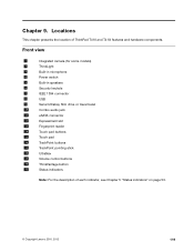
Front view 1 Integrated camera (for some models) 2 ThinkLight 3 Built-in microphone 4 Power switch 5 Built-in speakers 6 Security keyhole 7 IEEE 1394 connector 8 USB 9 Serial Ultrabay Slim drive or travel bezel ... pad 16 TrackPoint buttons 17 TrackPoint pointing stick 18 UltraNav 19 Volume control buttons 20 ThinkVantage button 21 Status indicators Note: For the description of ThinkPad T410 and T410i features and hardware components. Locations This chapter presents the location of each indicator, see Chapter 5 "Status indicators" on page 53. © Copyright...
Front view 1 Integrated camera (for some models) 2 ThinkLight 3 Built-in microphone 4 Power switch 5 Built-in speakers 6 Security keyhole 7 IEEE 1394 connector 8 USB 9 Serial Ultrabay Slim drive or travel bezel ... pad 16 TrackPoint buttons 17 TrackPoint pointing stick 18 UltraNav 19 Volume control buttons 20 ThinkVantage button 21 Status indicators Note: For the description of ThinkPad T410 and T410i features and hardware components. Locations This chapter presents the location of each indicator, see Chapter 5 "Status indicators" on page 53. © Copyright...

