ThinkPad 390E Hard Drive Removal - Lenovo
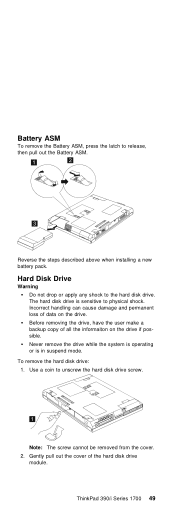
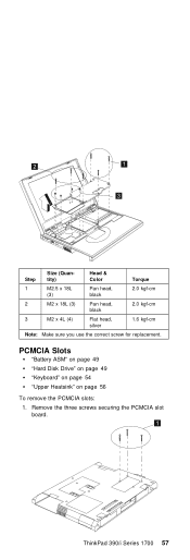
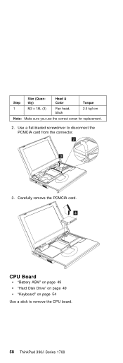
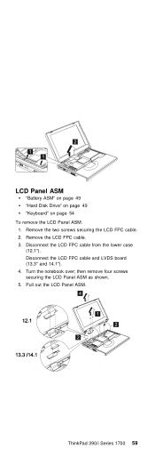
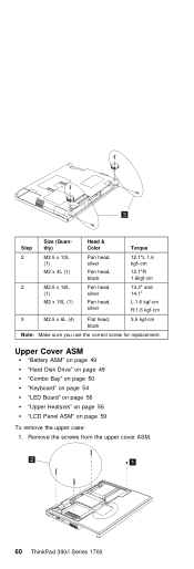
ThinkPad 390E Hard Drive Removal

View Results Below
Free Lenovo ThinkPad 390E manuals!
Problems with Lenovo ThinkPad 390E?
Ask a Question
Free Lenovo ThinkPad 390E manuals!
Problems with Lenovo ThinkPad 390E?
Ask a Question
Related Manual Pages

Similar Questions


Need To Clean Hard Drive, Space Is Very Low.
Looking for help trying to clean Hard Drive but Disk Space Manager us cleaning I think...
Looking for help trying to clean Hard Drive but Disk Space Manager us cleaning I think...
(Posted by Ntaylor79 10 years ago)

I Dont Have A Hard Drive Password What Should I Do?
i changed hard drive and dont havethe password
i changed hard drive and dont havethe password
(Posted by nkovtun2 12 years ago)