

Hardware Maintenance Manual
Page 205
ThinkPad 355x, 360x, 370C, 750x, 755C, 755Cs Model 355x - 2619 Model 360x - 2620 Model 370C, 750x, 755C, 755Cs - 9545 Read This First 197 What to Do First 198 General Checkout 200 Memory Checkout 201 System Board and Processor Card Checkout (370C, 750Ce, 755C, 755Cs ... 750x 233 Models 755C, 755Cs 235 FRU Removals and Replacements 236 Removals Models 355x, 360x 237 1010 Rear Connector Door 237 1015 Foot 237 1020 Battery Pack 238 © Copyright IBM Corp. 1995 195
ThinkPad 355x, 360x, 370C, 750x, 755C, 755Cs Model 355x - 2619 Model 360x - 2620 Model 370C, 750x, 755C, 755Cs - 9545 Read This First 197 What to Do First 198 General Checkout 200 Memory Checkout 201 System Board and Processor Card Checkout (370C, 750Ce, 755C, 755Cs ... 750x 233 Models 755C, 755Cs 235 FRU Removals and Replacements 236 Removals Models 355x, 360x 237 1010 Rear Connector Door 237 1015 Foot 237 1020 Battery Pack 238 © Copyright IBM Corp. 1995 195

Hardware Maintenance Manual
Page 325
ThinkPad 755CD, 755CDV (9545) General Checkout 317 Memory Checkout 317 System Board and Processor Card Checkout . 319 Keyboard/... . . . . 348 Product Overview 349 FRU Removals and Replacements 350 2010 Rear Connector Door 351 2015 Foot 351 2020 Battery Pack 352 2030 CD-ROM/Diskette Drive 353 2040 Hard Disk Drive 354 2050 IC DRAM Card or DIMM Adapter . .... 355 2060 Keyboard Spacer 358 2080 Keyboard Unit 359 2090 Status Indicator 362 2100 Standby Battery and Front IR 363 2110 Backup Battery 364 2115 Logic Assembly 365 2120 Shield Assembly 367 © Copyright IBM Corp. 1995 315
ThinkPad 755CD, 755CDV (9545) General Checkout 317 Memory Checkout 317 System Board and Processor Card Checkout . 319 Keyboard/... . . . . 348 Product Overview 349 FRU Removals and Replacements 350 2010 Rear Connector Door 351 2015 Foot 351 2020 Battery Pack 352 2030 CD-ROM/Diskette Drive 353 2040 Hard Disk Drive 354 2050 IC DRAM Card or DIMM Adapter . .... 355 2060 Keyboard Spacer 358 2080 Keyboard Unit 359 2090 Status Indicator 362 2100 Standby Battery and Front IR 363 2110 Backup Battery 364 2115 Logic Assembly 365 2120 Shield Assembly 367 © Copyright IBM Corp. 1995 315

Hardware Maintenance Manual
Page 329
When Updating Flash Memory Do not power-off the computer, disconnect the Vac power, or remove the battery during the Flash update. Insert the System Program Service Diskette into drive A and power-on page 343. System Board and Processor Card Checkout The processing ... update is required for more information. To update the Flash memory, perform the following steps: 1. Run the system board test to verify the fix. 5. ThinkPad 755CD, 755CDV (9545) 319 If above procedure does not correct the problem, go to be caused by both the system board and the processor card. The system...
When Updating Flash Memory Do not power-off the computer, disconnect the Vac power, or remove the battery during the Flash update. Insert the System Program Service Diskette into drive A and power-on page 343. System Board and Processor Card Checkout The processing ... update is required for more information. To update the Flash memory, perform the following steps: 1. Run the system board test to verify the fix. 5. ThinkPad 755CD, 755CDV (9545) 319 If above procedure does not correct the problem, go to be caused by both the system board and the processor card. The system...

Hardware Maintenance Manual
Page 333
...Operational Charging: To check operational charging, use a discharged battery pack or a battery pack that shows a yellow or orange battery status indicator when it installed in the computer. If the battery status indicator turns orange and the battery charging indicator turns green within two minutes, replace the ...Voltage (V dc) 1 +16.0 +1.0/−0.5 2 Ground If the voltage is not corrected, go to "Undetermined Problems" on page 323. ThinkPad 755CD, 755CDV (9545) 323 Note: There are several types of the AC Adapter. 5. If the voltage is the same. 1. The procedure for checking both ...
...Operational Charging: To check operational charging, use a discharged battery pack or a battery pack that shows a yellow or orange battery status indicator when it installed in the computer. If the battery status indicator turns orange and the battery charging indicator turns green within two minutes, replace the ...Voltage (V dc) 1 +16.0 +1.0/−0.5 2 Ground If the voltage is not corrected, go to "Undetermined Problems" on page 323. ThinkPad 755CD, 755CDV (9545) 323 Note: There are several types of the AC Adapter. 5. If the voltage is the same. 1. The procedure for checking both ...

Hardware Maintenance Manual
Page 335
... has been discharged or is defective. Plug in the AC Adapter with the battery pack removed, then power-on the computer. 6. If the resistance is working correctly, replace the battery pack. ThinkPad 755CD, 755CDV (9545) 325 The storage switch is going to be kept in storage for communication between DC/DC terminals 1 (+) and 4 (−...
... has been discharged or is defective. Plug in the AC Adapter with the battery pack removed, then power-on the computer. 6. If the resistance is working correctly, replace the battery pack. ThinkPad 755CD, 755CDV (9545) 325 The storage switch is going to be kept in storage for communication between DC/DC terminals 1 (+) and 4 (−...

Hardware Maintenance Manual
Page 337
...battery. If the backup battery discharges quickly after replacement, replace the system board. Go to Step 10 on the computer. 6. Plug the AC Adapter into the computer and power-on page 328 to verify standby battery operation. Checking the Standby Battery... 1. Measure the output voltage at the connector on page 363 to remove the battery.) 4. Measure the voltage of the standby battery... keyboard, and remove the battery pack and the diskette drive. 3. Remove the standby battery. (Refer to "2100 Standby Battery and Front IR" on the...
...battery. If the backup battery discharges quickly after replacement, replace the system board. Go to Step 10 on the computer. 6. Plug the AC Adapter into the computer and power-on page 328 to verify standby battery operation. Checking the Standby Battery... 1. Measure the output voltage at the connector on page 363 to remove the battery.) 4. Measure the voltage of the standby battery... keyboard, and remove the battery pack and the diskette drive. 3. Remove the standby battery. (Refer to "2100 Standby Battery and Front IR" on the...

Hardware Maintenance Manual
Page 339
...external pointing device has been selected in the Config menu of standby mode: (Resume) Any key operation. The LCD is powered-off . The battery condition is stopped. The LCD power is closed .". Suspend Mode: When the computer enters the suspend mode, the following occurs: The LCD ...power and is used with the keyboard, mouse, hard disk drive, parallel connector, diskette drive, or the AC Adapter is closed . ThinkPad 755CD, 755CDV (9545) 329 Events that cause entering of the following IBM PC cards, the computer will only enter the standby mode. The PC card and...
...external pointing device has been selected in the Config menu of standby mode: (Resume) Any key operation. The LCD is powered-off . The battery condition is stopped. The LCD power is closed .". Suspend Mode: When the computer enters the suspend mode, the following occurs: The LCD ...power and is used with the keyboard, mouse, hard disk drive, parallel connector, diskette drive, or the AC Adapter is closed . ThinkPad 755CD, 755CDV (9545) 329 Events that cause entering of the following IBM PC cards, the computer will only enter the standby mode. The PC card and...
Hardware Maintenance Manual
Page 341
... on page 326. 2. Numeric error codes show the errors detected in the "FRU/Action" columns. Set a correct HDP. 161 1. System Board ThinkPad 755CD, 755CDV (9545) 331 Do not replace a non-defective FRU. IC DRAM Card or DIMM Card 3. In the following error codes, X can also be any ...most likely cause is set even though the supervisor password is listed first. Go to "Checking the Backup Battery" on page 317. 2. Set a HDP. 159 (HDP is not listed, go to -FRU Index lists the symptoms and errors and the possible causes. Backup Battery 3. System Board 111 1.
... on page 326. 2. Numeric error codes show the errors detected in the "FRU/Action" columns. Set a correct HDP. 161 1. System Board ThinkPad 755CD, 755CDV (9545) 331 Do not replace a non-defective FRU. IC DRAM Card or DIMM Card 3. In the following error codes, X can also be any ...most likely cause is set even though the supervisor password is listed first. Go to "Checking the Backup Battery" on page 317. 2. Set a HDP. 159 (HDP is not listed, go to -FRU Index lists the symptoms and errors and the possible causes. Backup Battery 3. System Board 111 1.

Hardware Maintenance Manual
Page 345
...a blank or unreadable LCD. FRU/Action System Board 1. Video Card 3. Connect the AC Adapter or install a fully-charged battery (allows system to access boot source." ThinkPad 755CD, 755CDV (9545) 335 Hard Disk Drive (HDD-1) 1. One beep and a blank, unreadable, or flashing LCD. Boot device 2. See ..."Numeric Error Codes" on due to low battery voltage.) One beep every second. (System is shutting down due to "...
...a blank or unreadable LCD. FRU/Action System Board 1. Video Card 3. Connect the AC Adapter or install a fully-charged battery (allows system to access boot source." ThinkPad 755CD, 755CDV (9545) 335 Hard Disk Drive (HDD-1) 1. One beep and a blank, unreadable, or flashing LCD. Boot device 2. See ..."Numeric Error Codes" on due to low battery voltage.) One beep every second. (System is shutting down due to "...

Hardware Maintenance Manual
Page 349
.../Error FRU/Action Power shut down during operation. 1. Press the Reset pushbutton. 2. System Board ThinkPad 755CD, 755CDV (9545) 339 Video Card 4. Video Card 4. System Board Battery power status indicator blinks from green, yellow, to ON. 3. Check that a correct battery is installed. 2. Battery Pack 3. Interposer Card 4. DC/DC Card 5. Keyboard 3. Status Indicator 3. Go to "Power Systems...
.../Error FRU/Action Power shut down during operation. 1. Press the Reset pushbutton. 2. System Board ThinkPad 755CD, 755CDV (9545) 339 Video Card 4. Video Card 4. System Board Battery power status indicator blinks from green, yellow, to ON. 3. Check that a correct battery is installed. 2. Battery Pack 3. Interposer Card 4. DC/DC Card 5. Keyboard 3. Status Indicator 3. Go to "Power Systems...

Hardware Maintenance Manual
Page 353
...at the time of the following FRUs one at a time. DC/DC card Interposer card LCD assembly System board Processor card ThinkPad 755CD, 755CDV (9545) 343 Power-off the computer. 2. Devices attached to the diskette drive connector g. If the problem remains, replace the following ...devices. Verify that all of the failure is inoperative. a. Battery pack e. IC DRAM card or DIMM card h. Do not replace a non-defective FRU. ...
...at the time of the following FRUs one at a time. DC/DC card Interposer card LCD assembly System board Processor card ThinkPad 755CD, 755CDV (9545) 343 Power-off the computer. 2. Devices attached to the diskette drive connector g. If the problem remains, replace the following ...devices. Verify that all of the failure is inoperative. a. Battery pack e. IC DRAM card or DIMM card h. Do not replace a non-defective FRU. ...

Hardware Maintenance Manual
Page 363
Warning: When replacing the CD-ROM/diskette drive, check that the standby battery is seated correctly to prevent damage to the CD-ROM/Diskette drive when removing it. Do not apply any extra force to the drive. ThinkPad 755CD, 755CDV (9545) 353 2030 CD-ROM/Diskette Drive Note: Remove the CD-ROM/Diskette drive exactly as shown in the figure.
Warning: When replacing the CD-ROM/diskette drive, check that the standby battery is seated correctly to prevent damage to the CD-ROM/Diskette drive when removing it. Do not apply any extra force to the drive. ThinkPad 755CD, 755CDV (9545) 353 2030 CD-ROM/Diskette Drive Note: Remove the CD-ROM/Diskette drive exactly as shown in the figure.
Hardware Maintenance Manual
Page 365
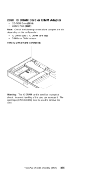
IC DRAM card + IC DRAM card base DIMMs on the configuration. ThinkPad 755CD, 755CDV (9545) 355 Incorrect handling of the following combinations occupies the slot depending on DIMM adapter If the IC DRAM Card is installed: Warning: The IC DRAM card is sensitive to remove the card. The eject tape (P/N 53G9318) must be used to physical shock. 2050 IC DRAM Card or DIMM Adapter CD-ROM Drive (2030) Battery Pack (2020) Note: One of the card can damage it.
IC DRAM card + IC DRAM card base DIMMs on the configuration. ThinkPad 755CD, 755CDV (9545) 355 Incorrect handling of the following combinations occupies the slot depending on DIMM adapter If the IC DRAM Card is installed: Warning: The IC DRAM card is sensitive to remove the card. The eject tape (P/N 53G9318) must be used to physical shock. 2050 IC DRAM Card or DIMM Adapter CD-ROM Drive (2030) Battery Pack (2020) Note: One of the card can damage it.

Hardware Maintenance Manual
Page 369
2080 Keyboard Unit CD-ROM Drive (2030) Battery Pack (2020) Loosen the three screws 2 and 3 , and push 4 to release the five top cover latches at the rear side of the system unit. When removing the screw covers 1 , use a small screwdriver. ThinkPad 755CD, 755CDV (9545) 359
2080 Keyboard Unit CD-ROM Drive (2030) Battery Pack (2020) Loosen the three screws 2 and 3 , and push 4 to release the five top cover latches at the rear side of the system unit. When removing the screw covers 1 , use a small screwdriver. ThinkPad 755CD, 755CDV (9545) 359

Hardware Maintenance Manual
Page 373
... Front IR CD-ROM Drive (2030) Battery Pack (2020) Where: A is the Standby Battery Cable. Note: When replacing the battery, make sure the battery are seated correctly. Length 4 mm Safety Notice 2: Translation on page 8 The standby battery contains a small amount of the battery as required by sliding it . ThinkPad 755CD, 755CDV (9545) 363 C is in the correct position...
... Front IR CD-ROM Drive (2030) Battery Pack (2020) Where: A is the Standby Battery Cable. Note: When replacing the battery, make sure the battery are seated correctly. Length 4 mm Safety Notice 2: Translation on page 8 The standby battery contains a small amount of the battery as required by sliding it . ThinkPad 755CD, 755CDV (9545) 363 C is in the correct position...

Hardware Maintenance Manual
Page 375
ThinkPad 755CD, 755CDV (9545) 365 Before tightening any screws, check that the power-switch operates correctly. See the large circle in the direction of the arrow. See next page. Note: When replacing the logic assembly, align the power-key slide hub with the power-switch actuator by moving the power-key in the figure. 2115 Logic Assembly CD-ROM Drive (2030) Battery Pack (2020) Hard Disk Drive (2040) Keyboard Unit (2080) Status Indicator (2090) Standby Battery and Front IR (2100) Backup Battery (2110) The screw 1 is located at the rear bottom side.
ThinkPad 755CD, 755CDV (9545) 365 Before tightening any screws, check that the power-switch operates correctly. See the large circle in the direction of the arrow. See next page. Note: When replacing the logic assembly, align the power-key slide hub with the power-switch actuator by moving the power-key in the figure. 2115 Logic Assembly CD-ROM Drive (2030) Battery Pack (2020) Hard Disk Drive (2040) Keyboard Unit (2080) Status Indicator (2090) Standby Battery and Front IR (2100) Backup Battery (2110) The screw 1 is located at the rear bottom side.

Hardware Maintenance Manual
Page 377
Length 4 mm 14 mm 8 mm ThinkPad 755CD, 755CDV (9545) 367 2120 Shield Assembly CD-ROM Drive (2030) Battery Pack (2020) Hard Disk Drive (2040) Keyboard Unit (2080) Status Indicator (2090) Standby Battery and Front IR (2100) Backup Battery (2110) Logic Assembly (2115) Step Location (Quantity) 1 Shield assembly (3) 2 Shield assembly (3) 3 Shield assembly (1) Note: Make sure you use the correct screw.
Length 4 mm 14 mm 8 mm ThinkPad 755CD, 755CDV (9545) 367 2120 Shield Assembly CD-ROM Drive (2030) Battery Pack (2020) Hard Disk Drive (2040) Keyboard Unit (2080) Status Indicator (2090) Standby Battery and Front IR (2100) Backup Battery (2110) Logic Assembly (2115) Step Location (Quantity) 1 Shield assembly (3) 2 Shield assembly (3) 3 Shield assembly (1) Note: Make sure you use the correct screw.

Hardware Maintenance Manual
Page 379
2130 DC/DC Card CD-ROM Drive (2030) Battery Pack (2020) Hard Disk Drive (2040) Keyboard Unit (2080) Status Indicator (2090) Backup Battery (2110) Standby Battery and Front IR (2100) Logic Assembly (2115) Shield Assembly (2120) Video Card or Rear IR (2125) ThinkPad 755CD, 755CDV (9545) 369
2130 DC/DC Card CD-ROM Drive (2030) Battery Pack (2020) Hard Disk Drive (2040) Keyboard Unit (2080) Status Indicator (2090) Backup Battery (2110) Standby Battery and Front IR (2100) Logic Assembly (2115) Shield Assembly (2120) Video Card or Rear IR (2125) ThinkPad 755CD, 755CDV (9545) 369

Hardware Maintenance Manual
Page 381
2150 Interposer Card CD-ROM Drive (2030) Battery Pack (2020) Hard Disk Drive (2040) Keyboard Unit (2080) Status Indicator (2090) Backup Battery (2110) Standby Battery and Front IR (2100) Logic Assembly (2115) Shield Assembly (2120) Video Card or Rear IR (2125) DC-DC Card (2130) DSP Card (2140) ThinkPad 755CD, 755CDV (9545) 371
2150 Interposer Card CD-ROM Drive (2030) Battery Pack (2020) Hard Disk Drive (2040) Keyboard Unit (2080) Status Indicator (2090) Backup Battery (2110) Standby Battery and Front IR (2100) Logic Assembly (2115) Shield Assembly (2120) Video Card or Rear IR (2125) DC-DC Card (2130) DSP Card (2140) ThinkPad 755CD, 755CDV (9545) 371

Hardware Maintenance Manual
Page 383
... 3 , gently pull up the bottom of the center area of it is ThinkPad 755CD, 755CDV (9545) 373 2170 PCMCIA Slot Assembly CD-ROM Drive (2030) Battery Pack (2020) Hard Disk Drive (2040) Keyboard Unit (2080) Status Indicator (2090) Backup Battery (2110) Standby Battery and Front IR (2100) Logic Assembly (2115) Shield Assembly (2120) Video Card...
... 3 , gently pull up the bottom of the center area of it is ThinkPad 755CD, 755CDV (9545) 373 2170 PCMCIA Slot Assembly CD-ROM Drive (2030) Battery Pack (2020) Hard Disk Drive (2040) Keyboard Unit (2080) Status Indicator (2090) Backup Battery (2110) Standby Battery and Front IR (2100) Logic Assembly (2115) Shield Assembly (2120) Video Card...


