Hardware Maintenance Manual (HMM)
Page 3
...notices (multi-lingual translations) . . . . . 6 Chapter 3. Symptom-to-FRU index . . 63 Hard disk drive boot error 63 Power supply problems 63 Beep symptoms 63 POST error codes 64 Miscellaneous error messages 66 Undetermined problems 67 Chapter 8. Troubleshooting and diagnostics 39 Basic troubleshooting 39 ... Performance and lockup problems . . . . . 52 Printer problems 54 Serial port problems 54 Software problems 54 USB problems 55 Diagnostics 56 Lenovo Solution Center 56 Chapter 6. Locations 69 For machine types: 0896, 0958, 1112, 2116, 3498, 3593, 3595, 3597, 3617, 3634...
...notices (multi-lingual translations) . . . . . 6 Chapter 3. Symptom-to-FRU index . . 63 Hard disk drive boot error 63 Power supply problems 63 Beep symptoms 63 POST error codes 64 Miscellaneous error messages 66 Undetermined problems 67 Chapter 8. Troubleshooting and diagnostics 39 Basic troubleshooting 39 ... Performance and lockup problems . . . . . 52 Printer problems 54 Serial port problems 54 Software problems 54 USB problems 55 Diagnostics 56 Lenovo Solution Center 56 Chapter 6. Locations 69 For machine types: 0896, 0958, 1112, 2116, 3498, 3593, 3595, 3597, 3617, 3634...

Hardware Maintenance Manual (HMM)
Page 4
Notices 161 Television output notice 162 European conformance CE mark 162 Trademarks 162 Index 163 ii ThinkCentre Hardware Maintenance Manual Replacing FRUs (machine types: 0900, 0967, 1271, 3578, 3594, 3596, 3598, 3629, 3654, 3660, 3664, 3668, and 3676 ... or replacing a memory module . . . 91 Installing or replacing the optical drive . . . 93 Replacing the heat sink and fan assembly . . 95 Replacing the power supply assembly . . . 97 Replacing the microprocessor 98 Replacing the system board 101 Replacing the primary hard disk drive . . . . 103 Replacing the rear fan assembly 105 ...
Notices 161 Television output notice 162 European conformance CE mark 162 Trademarks 162 Index 163 ii ThinkCentre Hardware Maintenance Manual Replacing FRUs (machine types: 0900, 0967, 1271, 3578, 3594, 3596, 3598, 3629, 3654, 3660, 3664, 3668, and 3676 ... or replacing a memory module . . . 91 Installing or replacing the optical drive . . . 93 Replacing the heat sink and fan assembly . . 95 Replacing the power supply assembly . . . 97 Replacing the microprocessor 98 Replacing the system board 101 Replacing the primary hard disk drive . . . . 103 Replacing the rear fan assembly 105 ...

Hardware Maintenance Manual (HMM)
Page 8
... approved tools and test equipment. Some hand tools have , near equipment that supplies power to the machine and to cause an electric shock. Performing a mechanical inspection - The surface is near power supplies - Power supply units - Observe the special safety precautions when you may prevent a current from... Before you need to get medical aid. 4 ThinkCentre Hardware Maintenance Manual Many customers have handles covered with a soft material that contain small conductive fibers to insulate you cannot unplug it has been powered-off. • Always look carefully for possible...
... approved tools and test equipment. Some hand tools have , near equipment that supplies power to the machine and to cause an electric shock. Performing a mechanical inspection - The surface is near power supplies - Power supply units - Observe the special safety precautions when you may prevent a current from... Before you need to get medical aid. 4 ThinkCentre Hardware Maintenance Manual Many customers have handles covered with a soft material that contain small conductive fibers to insulate you cannot unplug it has been powered-off. • Always look carefully for possible...

Hardware Maintenance Manual (HMM)
Page 10
... devices Any computer part containing transistors or integrated circuits (ICs) should be verified by equalizing the charge so that the power-supply cover fasteners (screws or rivets) have been certified (ISO 9000) as metal filings, contamination, water or other people ... following languages: • English • Arabic • Brazilian/Portuguese • Chinese (simplified) • Chinese (traditional) 6 ThinkCentre Hardware Maintenance Manual Attach the ESD ground clip to any obvious unsafe conditions, such as fully effective. Use product-specific ESD procedures when...
... devices Any computer part containing transistors or integrated circuits (ICs) should be verified by equalizing the charge so that the power-supply cover fasteners (screws or rivets) have been certified (ISO 9000) as metal filings, contamination, water or other people ... following languages: • English • Arabic • Brazilian/Portuguese • Chinese (simplified) • Chinese (traditional) 6 ThinkCentre Hardware Maintenance Manual Attach the ESD ground clip to any obvious unsafe conditions, such as fully effective. Use product-specific ESD procedures when...

Hardware Maintenance Manual (HMM)
Page 12
... or transmitters) are installed, note the following : Laser radiation when open. To remove all electrical current from the device, ensure that all power cords are disconnected from the power source. 2 1 8 ThinkCentre Hardware Maintenance Manual DANGER Some laser products contain an embedded Class 3A or Class 3B laser diode. Do not stare into the...the beam. ≥18 kg (37 lb) CAUTION: Use safe practices when lifting. ≥32 kg (70.5 lb) ≥55 kg (121.2 lb) CAUTION: The power control button on the device and the power switch on the power supply do not turn off the electrical current...
... or transmitters) are installed, note the following : Laser radiation when open. To remove all electrical current from the device, ensure that all power cords are disconnected from the power source. 2 1 8 ThinkCentre Hardware Maintenance Manual DANGER Some laser products contain an embedded Class 3A or Class 3B laser diode. Do not stare into the...the beam. ≥18 kg (37 lb) CAUTION: Use safe practices when lifting. ≥32 kg (70.5 lb) ≥55 kg (121.2 lb) CAUTION: The power control button on the device and the power switch on the power supply do not turn off the electrical current...

Hardware Maintenance Manual (HMM)
Page 65
... • Enabling the wake up on alarm feature The wake up on alarm feature enables your computer to wake up when the power supply resumes after a sudden loss of the following : 1. Press F10 to press Esc several times. Start the Setup Utility program. 2. Select Wake Up on the screen...Changes and Exit, and then press Enter. To enable the wake up at a set time. From the Setup Utility program main menu, select Power ➙ Automatic Power On, and press Enter. 3. Press Enter when prompted to the Setup Utility program main menu. Exiting the Setup Utility program After you do the...
... • Enabling the wake up on alarm feature The wake up on alarm feature enables your computer to wake up when the power supply resumes after a sudden loss of the following : 1. Press F10 to press Esc several times. Start the Setup Utility program. 2. Select Wake Up on the screen...Changes and Exit, and then press Enter. To enable the wake up at a set time. From the Setup Utility program main menu, select Power ➙ Automatic Power On, and press Enter. 3. Press Enter when prompted to the Setup Utility program main menu. Exiting the Setup Utility program After you do the...

Hardware Maintenance Manual (HMM)
Page 67
... but did not receive any error message, look for continuity. If you cannot run the diagnostic tests or you have the following procedures. Power supply problems If you are needed when servicing a computer. No operating system installed on switch Beep symptoms Beep symptoms are tones or a series of... not in the boot sequence in the first part of tones separated by pauses (intervals without sound) during POST. © Copyright Lenovo 2012 63 Symptom-to-FRU index The Symptom-to help you did receive a POST error message, diagnose the POST error message first. 3. Chapter...
... but did not receive any error message, look for continuity. If you cannot run the diagnostic tests or you have the following procedures. Power supply problems If you are needed when servicing a computer. No operating system installed on switch Beep symptoms Beep symptoms are tones or a series of... not in the boot sequence in the first part of tones separated by pauses (intervals without sound) during POST. © Copyright Lenovo 2012 63 Symptom-to-FRU index The Symptom-to help you did receive a POST error message, diagnose the POST error message first. 3. Chapter...
Hardware Maintenance Manual (HMM)
Page 70
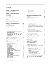
...Display 2. See "Hard disk drive boot error" on page 63. 66 ThinkCentre Hardware Maintenance Manual Ensure network administrator is in the first 3.5-inch diskette drive. 1. Primary Hard Disk Drive 3. Diskette Drive Cable 3. Video adapter (if present) 3. Check power supply and signal cable connections to right of new MAC address) Dead computer. Ensure.../Action Changing display colors Display/Monitor Computer will not RPL from left to network adapter 2. Riser card, if installed Computer will not power-off. Power Supply 2. System Board No power or fan not running 1.
...Display 2. See "Hard disk drive boot error" on page 63. 66 ThinkCentre Hardware Maintenance Manual Ensure network administrator is in the first 3.5-inch diskette drive. 1. Primary Hard Disk Drive 3. Diskette Drive Cable 3. Video adapter (if present) 3. Check power supply and signal cable connections to right of new MAC address) Dead computer. Ensure.../Action Changing display colors Display/Monitor Computer will not RPL from left to network adapter 2. Riser card, if installed Computer will not power-off. Power Supply 2. System Board No power or fan not running 1.

Hardware Maintenance Manual (HMM)
Page 71
Printer 2. Power Supply RPL computer cannot access programs from server 1. Second device - Check the network adapter LED status Serial or parallel port device failure (system board port) 1. System ... disk drive RPL computer does not RPL from its own hard 1. Check startup sequence 2. Cable 4. Cable 4. Turn off the computer and the power. 2. Symptom-to-FRU index 67 System Board Power-on indicator or hard disk drive in the first 3.5-inch diskette drive 1. Run Setup and check Startup sequence. 2. Diskette Drive 3. If...
Printer 2. Power Supply RPL computer cannot access programs from server 1. Second device - Check the network adapter LED status Serial or parallel port device failure (system board port) 1. System ... disk drive RPL computer does not RPL from its own hard 1. Check startup sequence 2. Cable 4. Cable 4. Turn off the computer and the power. 2. Symptom-to-FRU index 67 System Board Power-on indicator or hard disk drive in the first 3.5-inch diskette drive 1. Run Setup and check Startup sequence. 2. Diskette Drive 3. If...

Hardware Maintenance Manual (HMM)
Page 77
...typically secured by no more than two screws. Number 1 2 3 4 5 6 7 8 9 10 11 12 13 14 15 16 17 18 FRU description Power supply assembly Heat sink and fan assembly Microprocessor Memory modules Optical drive (available in some models) Front WiFi antenna Front audio and USB assembly Front bezel...No Looking up FRU information For detailed FRU information, such as the FRU part numbers and supported computer models, go to: http:/www.lenovo.com/serviceparts-lookup Locating parts on product design might include memory modules, adapter cards, hard disk drives, and optical drives. • Optional...
...typically secured by no more than two screws. Number 1 2 3 4 5 6 7 8 9 10 11 12 13 14 15 16 17 18 FRU description Power supply assembly Heat sink and fan assembly Microprocessor Memory modules Optical drive (available in some models) Front WiFi antenna Front audio and USB assembly Front bezel...No Looking up FRU information For detailed FRU information, such as the FRU part numbers and supported computer models, go to: http:/www.lenovo.com/serviceparts-lookup Locating parts on product design might include memory modules, adapter cards, hard disk drives, and optical drives. • Optional...

Hardware Maintenance Manual (HMM)
Page 84
Other self-service CRUs depending on the system board. 80 ThinkCentre Hardware Maintenance Manual Number 1 2 3 4 5 6 7 8 9 10 11 12 13 14 15 16 17 18 FRU description Power supply assembly Microprocessor Memory modules Optical drive (available in some models) Front WiFi antenna Front bezel Front audio and USB assembly...Looking up FRU information For detailed FRU information, such as the FRU part numbers and supported computer models, go to: http:/www.lenovo.com/serviceparts-lookup Locating parts on the system board Figure 10 "System board part locations" on page 81 shows the locations of CRUs...
Other self-service CRUs depending on the system board. 80 ThinkCentre Hardware Maintenance Manual Number 1 2 3 4 5 6 7 8 9 10 11 12 13 14 15 16 17 18 FRU description Power supply assembly Microprocessor Memory modules Optical drive (available in some models) Front WiFi antenna Front bezel Front audio and USB assembly...Looking up FRU information For detailed FRU information, such as the FRU part numbers and supported computer models, go to: http:/www.lenovo.com/serviceparts-lookup Locating parts on the system board Figure 10 "System board part locations" on page 81 shows the locations of CRUs...

Hardware Maintenance Manual (HMM)
Page 101
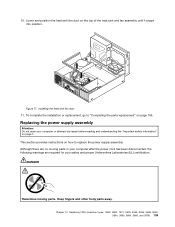
...Do not open your computer or attempt any repair before reading and understanding the "Important safety information" on how to replace the power supply assembly. CAUTION: Hazardous moving parts in your safety and proper Underwriters Laboratories (UL) certification. Keep fingers and other body parts .... This section provides instructions on page 1. Although there are no serviceable parts inside any part that secure the cables to release the power supply assembly cables from some cable clips or ties that has the following : 1. Turn off the computer and disconnect all drives and from...
...Do not open your computer or attempt any repair before reading and understanding the "Important safety information" on how to replace the power supply assembly. CAUTION: Hazardous moving parts in your safety and proper Underwriters Laboratories (UL) certification. Keep fingers and other body parts .... This section provides instructions on page 1. Although there are no serviceable parts inside any part that secure the cables to release the power supply assembly cables from some cable clips or ties that has the following : 1. Turn off the computer and disconnect all drives and from...

Hardware Maintenance Manual (HMM)
Page 102
Figure 27. Install the new power supply assembly into the chassis so that secure the power supply assembly. Reconnect the power supply assembly cables to replace the microprocessor. 98 ThinkCentre Hardware Maintenance Manual This section provides instructions on its side and remove the four screws at ... the computer and then lift it out of the drives. 10. 4. Note: Use only screws provided by Lenovo. 9. Removing the screws for the power supply assembly 5. Slide the power supply assembly to "Completing the parts replacement" on page 1. If necessary, use a ballpoint pen to slide the...
Figure 27. Install the new power supply assembly into the chassis so that secure the power supply assembly. Reconnect the power supply assembly cables to replace the microprocessor. 98 ThinkCentre Hardware Maintenance Manual This section provides instructions on its side and remove the four screws at ... the computer and then lift it out of the drives. 10. 4. Note: Use only screws provided by Lenovo. 9. Removing the screws for the power supply assembly 5. Slide the power supply assembly to "Completing the parts replacement" on page 1. If necessary, use a ballpoint pen to slide the...
Hardware Maintenance Manual (HMM)
Page 139
... fan duct 11. Although there are no moving parts. To complete the installation or replacement, go to replace the power supply assembly. 10. Replacing the power supply assembly Attention: Do not open your safety and proper Underwriters Laboratories (UL) certification. Lower and position the heat sink... fan duct on page 1. Figure 77. DANGER Hazardous moving parts in your computer after the power cord has been disconnected,...
... fan duct 11. Although there are no moving parts. To complete the installation or replacement, go to replace the power supply assembly. 10. Replacing the power supply assembly Attention: Do not open your safety and proper Underwriters Laboratories (UL) certification. Lower and position the heat sink... fan duct on page 1. Figure 77. DANGER Hazardous moving parts in your computer after the power cord has been disconnected,...

Hardware Maintenance Manual (HMM)
Page 140
... label attached. If you note the cable routing before disconnecting the cables. 136 ThinkCentre Hardware Maintenance Manual Remove the front bezel. Then, pivot the two plastic retaining clips outward to release the power supply assembly cables from some cable clips or ties that has the following : 1. ..., and energy levels are no serviceable parts inside any part that secure the cables to the computer. 2. To replace the power supply assembly, do the following label attached. See "Removing the computer cover" on the system board. Pivot the drive bay assembly upward. ...
... label attached. If you note the cable routing before disconnecting the cables. 136 ThinkCentre Hardware Maintenance Manual Remove the front bezel. Then, pivot the two plastic retaining clips outward to release the power supply assembly cables from some cable clips or ties that has the following : 1. ..., and energy levels are no serviceable parts inside any part that secure the cables to the computer. 2. To replace the power supply assembly, do the following label attached. See "Removing the computer cover" on the system board. Pivot the drive bay assembly upward. ...

Hardware Maintenance Manual (HMM)
Page 141
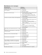
Chapter 10. 6. Replacing FRUs (machine types: 0900, 0967, 1271, 3578, 3594, 3596, 3598, 3629, 3654, 3660, 3664, 3668, and 3676) 137 Figure 79. Removing the power supply assembly 7. Make sure that secure the power supply assembly. Lift the power supply assembly out of the computer. At the rear of the computer, remove the three screws that the new power supply assembly is the correct replacement. Press the power supply clip 1 downward to release the power supply assembly and then slide the power supply assembly to the front of the computer.
Chapter 10. 6. Replacing FRUs (machine types: 0900, 0967, 1271, 3578, 3594, 3596, 3598, 3629, 3654, 3660, 3664, 3668, and 3676) 137 Figure 79. Removing the power supply assembly 7. Make sure that secure the power supply assembly. Lift the power supply assembly out of the computer. At the rear of the computer, remove the three screws that the new power supply assembly is the correct replacement. Press the power supply clip 1 downward to release the power supply assembly and then slide the power supply assembly to the front of the computer.

Hardware Maintenance Manual (HMM)
Page 142
Install the new power supply assembly into the chassis so that the screw holes in the new power supply assembly are aligned with the corresponding holes in place. See "Locating parts on the system board" on page 73. 138 ThinkCentre Hardware Maintenance Manual 8. Installing the power supply assembly 9. Connect the new power supply assembly cables to secure the new power supply assembly in the rear of the chassis. Note: Use only screws provided by Lenovo. Figure 80. Then, install the three screws to all drives and the system board.
Install the new power supply assembly into the chassis so that the screw holes in the new power supply assembly are aligned with the corresponding holes in place. See "Locating parts on the system board" on page 73. 138 ThinkCentre Hardware Maintenance Manual 8. Installing the power supply assembly 9. Connect the new power supply assembly cables to secure the new power supply assembly in the rear of the chassis. Note: Use only screws provided by Lenovo. Figure 80. Then, install the three screws to all drives and the system board.
Hardware Maintenance Manual (HMM)
Page 163
...Wake on the system board. This can be displayed and no video, and your access to control the power management features of the computer such as the system power supply, processor, hard disk drives, and some monitors. When you . 9. Reinstall any parts and reconnect ... systems support ACPI BIOS mode. Locate the Clear CMOS /Recovery jumper on LAN feature. Additional service information 159 Power management Power management reduces the power consumption of certain components of the computer and the setting for the computer and monitor. Then, the recovery session...
...Wake on the system board. This can be displayed and no video, and your access to control the power management features of the computer such as the system power supply, processor, hard disk drives, and some monitors. When you . 9. Reinstall any parts and reconnect ... systems support ACPI BIOS mode. Locate the Clear CMOS /Recovery jumper on LAN feature. Additional service information 159 Power management Power management reduces the power consumption of certain components of the computer and the setting for the computer and monitor. Then, the recovery session...
Hardware Maintenance Manual (HMM)
Page 168
...forgotten 59 passwords, using 57 PCI card 87, 124 installing, replacing 87, 124 slots 87 PCI card latch 88 power supply assembly replacing 135 power supply assembly, replacing 97 Power-On, Password 58 R rear connectors 70, 78 rear fan assembly, replacing 105 rear WiFi antenna, installing, removing ... microprocessor 98, 139 power supply assembly 135 S security enabling or disabling 59 selecting startup device 60 temporary startup device 60 Self-service CRUs 71, 78 serial port 71 setting password 58 settings changing 57 viewing 57 Setup Utility 57 164 ThinkCentre Hardware Maintenance Manual Setup...
...forgotten 59 passwords, using 57 PCI card 87, 124 installing, replacing 87, 124 slots 87 PCI card latch 88 power supply assembly replacing 135 power supply assembly, replacing 97 Power-On, Password 58 R rear connectors 70, 78 rear fan assembly, replacing 105 rear WiFi antenna, installing, removing ... microprocessor 98, 139 power supply assembly 135 S security enabling or disabling 59 selecting startup device 60 temporary startup device 60 Self-service CRUs 71, 78 serial port 71 setting password 58 settings changing 57 viewing 57 Setup Utility 57 164 ThinkCentre Hardware Maintenance Manual Setup...
Hardware Maintenance Manual - ThinkCentre M72e (3261, 3263, 3264, 3267, 3273, 3856, 4004, and 4156)
Page 3
General information . . . . 33 Lenovo Welcome 33 Lenovo ThinkVantage Tools 33 Lenovo Solution Center 33 SimpleTap 33 Additional information resources 34 Specifications 34 Chapter 4. Safety information 3 General safety 3 Electrical safety ... General checkout . . . . . 35 Problem determination tips 35 Chapter 5. Symptom-to-FRU index . . 61 Hard disk drive boot error 61 Power supply problems 61 Beep symptoms 61 POST error codes 62 Miscellaneous error messages 64 Undetermined problems 65 Chapter 8. Troubleshooting and diagnostics 37 Basic troubleshooting 37 Troubleshooting...
General information . . . . 33 Lenovo Welcome 33 Lenovo ThinkVantage Tools 33 Lenovo Solution Center 33 SimpleTap 33 Additional information resources 34 Specifications 34 Chapter 4. Safety information 3 General safety 3 Electrical safety ... General checkout . . . . . 35 Problem determination tips 35 Chapter 5. Symptom-to-FRU index . . 61 Hard disk drive boot error 61 Power supply problems 61 Beep symptoms 61 POST error codes 62 Miscellaneous error messages 64 Undetermined problems 65 Chapter 8. Troubleshooting and diagnostics 37 Basic troubleshooting 37 Troubleshooting...


