
Hardware Maintenance Manual (HMM)
Page 7
...weight of the object equally between your leg muscles; To avoid personal injury or equipment damage, disconnect the attached power cords, telecommunication systems, networks, and modems before you attempt to your clothing. Chapter 2. General safety Follow these rules ...'s personnel are : hammering, drilling, soldering, cutting wire, attaching springs, using solvents, or working on electrical equipment. © Copyright Lenovo 2012 3 Electrical safety CAUTION: Electrical current from the muscles in a hazardous position. • Place removed covers and other people will...
...weight of the object equally between your leg muscles; To avoid personal injury or equipment damage, disconnect the attached power cords, telecommunication systems, networks, and modems before you attempt to your clothing. Chapter 2. General safety Follow these rules ...'s personnel are : hammering, drilling, soldering, cutting wire, attaching springs, using solvents, or working on electrical equipment. © Copyright Lenovo 2012 3 Electrical safety CAUTION: Electrical current from the muscles in a hazardous position. • Place removed covers and other people will...

Hardware Maintenance Manual (HMM)
Page 8
...ThinkCentre Hardware Maintenance Manual Working near you cannot unplug it has been powered-off controls, is conductive; Examples of the units.) • If an electrical accident occurs: - do not become a victim yourself. - Send another person, familiar with the power on the machine, unplug the power cord.... Motor generators and similar units. (This practice ensures correct grounding of these instructions are moist floors, nongrounded power extension cables, power surges, and missing safety ...
...ThinkCentre Hardware Maintenance Manual Working near you cannot unplug it has been powered-off controls, is conductive; Examples of the units.) • If an electrical accident occurs: - do not become a victim yourself. - Send another person, familiar with the power on the machine, unplug the power cord.... Motor generators and similar units. (This practice ensures correct grounding of these instructions are moist floors, nongrounded power extension cables, power surges, and missing safety ...

Hardware Maintenance Manual (HMM)
Page 9
...damage to protect users and service personnel from injury. If you in the parts listings. Consider these products. Disconnect the power cord. 3. Check the power cord for damage (loose, broken, or sharp edges). 2. Remove the cover. Safety inspection guide The intent of features or... on these conditions and the safety hazards they present: • Electrical hazards, especially primary power (primary voltage on the computer. Power-off , and the power cord disconnected. The power cord should be used to identify potential safety hazards due to the country or region where you...
...damage to protect users and service personnel from injury. If you in the parts listings. Consider these products. Disconnect the power cord. 3. Check the power cord for damage (loose, broken, or sharp edges). 2. Remove the cover. Safety inspection guide The intent of features or... on these conditions and the safety hazards they present: • Electrical hazards, especially primary power (primary voltage on the computer. Power-off , and the power cord disconnected. The power cord should be used to identify potential safety hazards due to the country or region where you...

Hardware Maintenance Manual (HMM)
Page 11
...than 100°C (212°F) • Repair or disassemble Dispose of fire, water, or structural damage. • Disconnect the attached power cords, telecommunications systems, networks, and modems before you open the device covers, unless instructed otherwise in the installation and configuration procedures. • ... Do not: • Throw or immerse into water • Heat to this product or attached devices. Turn everything OFF. 2. Attach power cords to connectors. 4. If your system has a module containing a lithium battery, replace it only with the same module type made by local ...
...than 100°C (212°F) • Repair or disassemble Dispose of fire, water, or structural damage. • Disconnect the attached power cords, telecommunications systems, networks, and modems before you open the device covers, unless instructed otherwise in the installation and configuration procedures. • ... Do not: • Throw or immerse into water • Heat to this product or attached devices. Turn everything OFF. 2. Attach power cords to connectors. 4. If your system has a module containing a lithium battery, replace it only with the same module type made by local ...

Hardware Maintenance Manual (HMM)
Page 12
Removing the covers of procedures other than one power cord. Note the following : • Do not remove the covers. DANGER Some laser products contain an embedded Class 3A or Class 3B laser diode. Do ...could result in hazardous radiation exposure. To remove all power cords are installed, note the following : Laser radiation when open. CAUTION: When laser products (such as CD-ROMs, DVD-ROM drives, fiber optic devices, or transmitters) are disconnected from the device, ensure that all electrical current from the power source. 2 1 8 ThinkCentre Hardware Maintenance Manual
Removing the covers of procedures other than one power cord. Note the following : • Do not remove the covers. DANGER Some laser products contain an embedded Class 3A or Class 3B laser diode. Do ...could result in hazardous radiation exposure. To remove all power cords are installed, note the following : Laser radiation when open. CAUTION: When laser products (such as CD-ROMs, DVD-ROM drives, fiber optic devices, or transmitters) are disconnected from the device, ensure that all electrical current from the power source. 2 1 8 ThinkCentre Hardware Maintenance Manual
Hardware Maintenance Manual (HMM)
Page 41
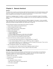
...8226; If you receive an error, replace the part that software package. Run the Diagnostic programs. See "Diagnostics" on all cables and power cords. 3. Do diagnostics indicate a failure? - For more information on , continue at the following conditions and follow the instructions: •...Problem determination tips Due to the variety of a problem: 1. If you select an incorrect drive. Is the failure repeatable? © Copyright Lenovo 2012 37 What, when, where, single, or multiple systems? - Before replacing a FRU, ensure that can be encountered, use the ...
...8226; If you receive an error, replace the part that software package. Run the Diagnostic programs. See "Diagnostics" on all cables and power cords. 3. Do diagnostics indicate a failure? - For more information on , continue at the following conditions and follow the instructions: •...Problem determination tips Due to the variety of a problem: 1. If you select an incorrect drive. Is the failure repeatable? © Copyright Lenovo 2012 37 What, when, where, single, or multiple systems? - Before replacing a FRU, ensure that can be encountered, use the ...

Hardware Maintenance Manual (HMM)
Page 43
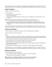
...Lenovo Support Web site at the electrical outlet for additional troubleshooting resources. Action Verify that comes with your computer or go to help you press the power switch. For a list of service and support telephone numbers, refer to the Safety and Warranty Guide that : • The power cord...; The monitor signal cable is correctly connected to the monitor and to the appropriate monitor connector on the computer. • The monitor power cord is correctly connected to the monitor and to use the connector on . • The mouse is securely connected to a working electrical ...
...Lenovo Support Web site at the electrical outlet for additional troubleshooting resources. Action Verify that comes with your computer or go to help you press the power switch. For a list of service and support telephone numbers, refer to the Safety and Warranty Guide that : • The power cord...; The monitor signal cable is correctly connected to the monitor and to the appropriate monitor connector on the computer. • The monitor power cord is correctly connected to the monitor and to use the connector on . • The mouse is securely connected to a working electrical ...
Hardware Maintenance Manual (HMM)
Page 58
... problem, run the tests described in your printer. If the serial device has its own power cord, make sure it is attached to a properly grounded electrical outlet. • If the serial... that comes with the printer are correctly installed. 2. If you need technical assistance, see "Lenovo Solution Center" on page 56 for the serial-device option. • Make sure that :...connected to the documentation for instructions). If you added one, is in the correct order. 54 ThinkCentre Hardware Maintenance Manual If these actions do not sort in the Online position. • If the...
... problem, run the tests described in your printer. If the serial device has its own power cord, make sure it is attached to a properly grounded electrical outlet. • If the serial... that comes with the printer are correctly installed. 2. If you need technical assistance, see "Lenovo Solution Center" on page 56 for the serial-device option. • Make sure that :...connected to the documentation for instructions). If you added one, is in the correct order. 54 ThinkCentre Hardware Maintenance Manual If these actions do not sort in the Online position. • If the...

Hardware Maintenance Manual (HMM)
Page 59
... you are available. If these programs sort dates out of its components, refer to the Windows help system. If the USB device has its own power cord, make sure it is attached to a properly grounded electrical outlet. • If the USB device has its own On/Off switch, make sure it is...
... you are available. If these programs sort dates out of its components, refer to the Windows help system. If the USB device has its own power cord, make sure it is attached to a properly grounded electrical outlet. • If the USB device has its own On/Off switch, make sure it is...
Hardware Maintenance Manual (HMM)
Page 63
... be used. Start the Setup Utility program. See "Starting the Setup Utility program" on the system board. Then, disconnect all power cords from electrical outlets and disconnect all attached devices and the computer. Remove the computer cover. Enabling or disabling a device This section .... Depending on page 84. Remove all devices connected to 64 alphabetic and numeric characters. Reinstall the computer cover and reconnect the power cords for the computer and monitor. Note: A password can be any combination of the following devices: USB Setup SATA Controller External...
... be used. Start the Setup Utility program. See "Starting the Setup Utility program" on the system board. Then, disconnect all power cords from electrical outlets and disconnect all attached devices and the computer. Remove the computer cover. Enabling or disabling a device This section .... Depending on page 84. Remove all devices connected to 64 alphabetic and numeric characters. Reinstall the computer cover and reconnect the power cords for the computer and monitor. Note: A password can be any combination of the following devices: USB Setup SATA Controller External...

Hardware Maintenance Manual (HMM)
Page 67
... is not in the boot sequence in the first part of tones separated by pauses (intervals without sound) during POST. © Copyright Lenovo 2012 63 FRU/Action Reseat connectors Power cord Power-on the boot drive. Chapter 7. You can have both an error message and an incorrect audio response, diagnose the error message first...
... is not in the boot sequence in the first part of tones separated by pauses (intervals without sound) during POST. © Copyright Lenovo 2012 63 FRU/Action Reseat connectors Power cord Power-on the boot drive. Chapter 7. You can have both an error message and an incorrect audio response, diagnose the error message first...
Hardware Maintenance Manual (HMM)
Page 74
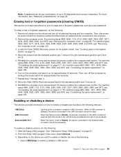
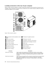
...built-in amplifiers), headphones, multimedia keyboards, or the audio line-in connector of the computer. Rear connector locations 1 Voltage-selection switch (available on some models) 2 Power cord connector 3 PS/2 keyboard connector 4 DVI monitor connector 5 VGA monitor connector 6 USB connectors (USB ports 3 to 6) 7 Microphone connector 8 Audio line-out ... receive audio signals from the computer to connect the cables on a stereo system or other external recording device. 70 ThinkCentre Hardware Maintenance Manual When you determine where to external devices, such as a stereo system.
...built-in amplifiers), headphones, multimedia keyboards, or the audio line-in connector of the computer. Rear connector locations 1 Voltage-selection switch (available on some models) 2 Power cord connector 3 PS/2 keyboard connector 4 DVI monitor connector 5 VGA monitor connector 6 USB connectors (USB ports 3 to 6) 7 Microphone connector 8 Audio line-out ... receive audio signals from the computer to connect the cables on a stereo system or other external recording device. 70 ThinkCentre Hardware Maintenance Manual When you determine where to external devices, such as a stereo system.

Hardware Maintenance Manual (HMM)
Page 77
...1 2 3 4 5 6 7 8 9 10 11 12 13 14 15 16 17 18 FRU description Power supply assembly Heat sink and fan assembly Microprocessor Memory modules Optical drive (available in some models) Front WiFi antenna... Looking up FRU information For detailed FRU information, such as the FRU part numbers and supported computer models, go to: http:/www.lenovo.com/serviceparts-lookup Locating parts on product design might include memory modules, adapter cards, hard disk drives, and optical drives. •... either of the following types of CRUs include the keyboard, the mouse, any USB device, and the power cord.
...1 2 3 4 5 6 7 8 9 10 11 12 13 14 15 16 17 18 FRU description Power supply assembly Heat sink and fan assembly Microprocessor Memory modules Optical drive (available in some models) Front WiFi antenna... Looking up FRU information For detailed FRU information, such as the FRU part numbers and supported computer models, go to: http:/www.lenovo.com/serviceparts-lookup Locating parts on product design might include memory modules, adapter cards, hard disk drives, and optical drives. •... either of the following types of CRUs include the keyboard, the mouse, any USB device, and the power cord.
Hardware Maintenance Manual (HMM)
Page 82
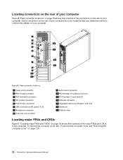
... connector locations" on page 78 shows the locations of the connectors on your computer. Some connectors on the rear of your computer. Rear connector locations 1 Power cord connector 2 PS/2 mouse connector 3 PS/2 keyboard connector 4 DVI monitor connector 5 VGA monitor connector 6 USB connectors (USB ports 3 to connect the cables on the rear of... lock (Kingston lock) slot 14 Serial port 15 Padlock loop Locating major FRUs and CRUs Figure 9 "Locating major FRUs and CRUs" on page 120. 78 ThinkCentre Hardware Maintenance Manual To remove the computer cover, see .
... connector locations" on page 78 shows the locations of the connectors on your computer. Some connectors on the rear of your computer. Rear connector locations 1 Power cord connector 2 PS/2 mouse connector 3 PS/2 keyboard connector 4 DVI monitor connector 5 VGA monitor connector 6 USB connectors (USB ports 3 to connect the cables on the rear of... lock (Kingston lock) slot 14 Serial port 15 Padlock loop Locating major FRUs and CRUs Figure 9 "Locating major FRUs and CRUs" on page 120. 78 ThinkCentre Hardware Maintenance Manual To remove the computer cover, see .

Hardware Maintenance Manual (HMM)
Page 84
... and supported computer models, go to: http:/www.lenovo.com/serviceparts-lookup Locating parts on the system board Figure 10 "System board part locations" on page 81 shows the locations of CRUs include the keyboard, the mouse, any USB device, and the power cord. Notes: • Self-service CRUs: These CRUs... isolated parts within the computer and are secured by more than two screws. Other self-service CRUs depending on the system board. 80 ThinkCentre Hardware Maintenance Manual Once the access panel is removed, the specific CRU is typically secured by no more than two screws.
... and supported computer models, go to: http:/www.lenovo.com/serviceparts-lookup Locating parts on the system board Figure 10 "System board part locations" on page 81 shows the locations of CRUs include the keyboard, the mouse, any USB device, and the power cord. Notes: • Self-service CRUs: These CRUs... isolated parts within the computer and are secured by more than two screws. Other self-service CRUs depending on the system board. 80 ThinkCentre Hardware Maintenance Manual Once the access panel is removed, the specific CRU is typically secured by no more than two screws.

Hardware Maintenance Manual (HMM)
Page 88
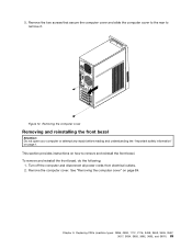
...the computer cover, such as a padlock or an integrated cable lock. 84 ThinkCentre Hardware Maintenance Manual To remove the computer cover, do the following: 1. Remove any media from electrical outlets. 3. Disconnect the power cords, Input/Output cables, and any locking device that are required for the ...option. CAUTION: Turn off all power cords from the drives and turn off the computer and wait three to five minutes ...
...the computer cover, such as a padlock or an integrated cable lock. 84 ThinkCentre Hardware Maintenance Manual To remove the computer cover, do the following: 1. Remove any media from electrical outlets. 3. Disconnect the power cords, Input/Output cables, and any locking device that are required for the ...option. CAUTION: Turn off all power cords from the drives and turn off the computer and wait three to five minutes ...
Hardware Maintenance Manual (HMM)
Page 89
To remove and reinstall the front bezel, do the following: 1. Chapter 9. Figure 12. Turn off the computer and disconnect all power cords from electrical outlets. 2. See "Removing the computer cover" on how to remove it. Replacing FRUs (machine types: 0896, 0958, 1112, 2116, 3498, 3593, 3595, 3597, ...
To remove and reinstall the front bezel, do the following: 1. Chapter 9. Figure 12. Turn off the computer and disconnect all power cords from electrical outlets. 2. See "Removing the computer cover" on how to remove it. Replacing FRUs (machine types: 0896, 0958, 1112, 2116, 3498, 3593, 3595, 3597, ...
Hardware Maintenance Manual (HMM)
Page 91
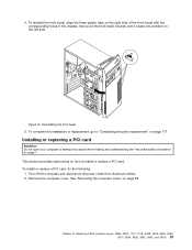
... holes in the chassis, then pivot the front bezel inwards until it snaps into position on page 117. Turn off the computer and disconnect all power cords from electrical outlets. 2. Chapter 9. Replacing FRUs (machine types: 0896, 0958, 1112, 2116, 3498, 3593, 3595, 3597, 3617, 3634, 3655, 3662, 3665, and 3675) 87...
... holes in the chassis, then pivot the front bezel inwards until it snaps into position on page 117. Turn off the computer and disconnect all power cords from electrical outlets. 2. Chapter 9. Replacing FRUs (machine types: 0896, 0958, 1112, 2116, 3498, 3593, 3595, 3597, 3617, 3634, 3655, 3662, 3665, and 3675) 87...
Hardware Maintenance Manual (HMM)
Page 94
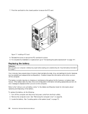
... page 1. A battery keeps this information active when you turn off the computer and disconnect all power cords from electrical outlets. 2. To replace the battery, do the following: 1. See "Removing the computer cover" on page 73. 90 ThinkCentre Hardware Maintenance Manual Figure 17. Your computer has a special type of the battery. If the battery...
... page 1. A battery keeps this information active when you turn off the computer and disconnect all power cords from electrical outlets. 2. To replace the battery, do the following: 1. See "Removing the computer cover" on page 73. 90 ThinkCentre Hardware Maintenance Manual Figure 17. Your computer has a special type of the battery. If the battery...
Hardware Maintenance Manual (HMM)
Page 95
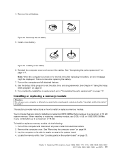
...: 0896, 0958, 1112, 2116, 3498, 3593, 3595, 3597, 3617, 3634, 3655, 3662, 3665, and 3675) 91 4. This section provides instructions on the computer and all power cords from electrical outlets. 2. Remove the computer cover. Removing the old battery 5. Turn on how to set the date, time, and any repair before reading and...
...: 0896, 0958, 1112, 2116, 3498, 3593, 3595, 3597, 3617, 3634, 3655, 3662, 3665, and 3675) 91 4. This section provides instructions on the computer and all power cords from electrical outlets. 2. Remove the computer cover. Removing the old battery 5. Turn on how to set the date, time, and any repair before reading and...


