Hardware Maintenance Manual (HMM)
Page 49
... installed with the operating system might overheat. If these actions do not correct the problem, run the diagnostic program Lenovo Solution Center. Note: In rare cases, the hard disk drive with five SATA hard disk drives, ensure that all cables and cords are securely connected to five hard disk drives) or the...
... installed with the operating system might overheat. If these actions do not correct the problem, run the diagnostic program Lenovo Solution Center. Note: In rare cases, the hard disk drive with five SATA hard disk drives, ensure that all cables and cords are securely connected to five hard disk drives) or the...
Hardware Maintenance Manual (HMM)
Page 63
...and 3676, see "Removing the computer cover" on page 117. Erasing lost or forgotten password, do the following devices: USB Setup SATA Controller External SATA Port Use this option is set to Disable, the device connected to Disable, all attached devices and the computer. Move the jumper from... electrical outlets and disconnect all cables that are disabled and cannot be accessed. When this feature is set to the External SATA connector cannot be accessed. See "Starting the Setup Utility program" on the system board. Using the Setup Utility program 59 For ...
...and 3676, see "Removing the computer cover" on page 117. Erasing lost or forgotten password, do the following devices: USB Setup SATA Controller External SATA Port Use this option is set to Disable, the device connected to Disable, all attached devices and the computer. Move the jumper from... electrical outlets and disconnect all cables that are disabled and cannot be accessed. When this feature is set to the External SATA connector cannot be accessed. See "Starting the Setup Utility program" on the system board. Using the Setup Utility program 59 For ...

Hardware Maintenance Manual (HMM)
Page 64
...computer does not start up from the Please select boot device window does not permanently change the configured startup device sequence, do the following : 60 ThinkCentre Hardware Maintenance Manual Selecting a temporary startup device Use this procedure to confirm the exit. Select the devices for the Primary Startup Sequence, the Automatic... press Enter. Press F10 to save changes and exit the Setup Utility program. Press F10 to enable or disable an internal or external SATA device. 4. • Select ATA Drive Setup to save changes and exit the Setup Utility program.
...computer does not start up from the Please select boot device window does not permanently change the configured startup device sequence, do the following : 60 ThinkCentre Hardware Maintenance Manual Selecting a temporary startup device Use this procedure to confirm the exit. Select the devices for the Primary Startup Sequence, the Automatic... press Enter. Press F10 to save changes and exit the Setup Utility program. Press F10 to enable or disable an internal or external SATA device. 4. • Select ATA Drive Setup to save changes and exit the Setup Utility program.
Hardware Maintenance Manual (HMM)
Page 78
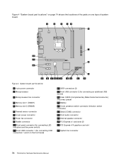
... and the power switch) 11 Front USB connector 1 (for connecting USB connectors 1 and 2 on one type of the parts on the front bezel) 12 SATA connectors (3) 13 Front USB connector 2 (for connecting an additional USB device) 14 Clear CMOS (Complementary Metal Oxide Semiconductor) /Recovery jumper 15 Battery 16 Cover ... connector 19 Internal speaker connector 20 PCI Express x1 card slots (2) 21 PCI Express x16 graphics card slot 22 System fan connector 74 ThinkCentre Hardware Maintenance Manual Figure 4. Figure 4 "System board part locations" on page 74 shows the locations of system board.
... and the power switch) 11 Front USB connector 1 (for connecting USB connectors 1 and 2 on one type of the parts on the front bezel) 12 SATA connectors (3) 13 Front USB connector 2 (for connecting an additional USB device) 14 Clear CMOS (Complementary Metal Oxide Semiconductor) /Recovery jumper 15 Battery 16 Cover ... connector 19 Internal speaker connector 20 PCI Express x1 card slots (2) 21 PCI Express x16 graphics card slot 22 System fan connector 74 ThinkCentre Hardware Maintenance Manual Figure 4. Figure 4 "System board part locations" on page 74 shows the locations of system board.
Hardware Maintenance Manual (HMM)
Page 79
... Power fan connector 11 Clear CMOS (Complementary Metal Oxide Semiconductor) /Recovery jumper 12 Front panel connector (for connecting LED indicators and the power switch) 13 SATA connectors (4) 14 Front USB connector 1 (for connecting USB connectors 1 and 2 on the other type of system board. Locations 75 Figure 5. Figure 5 "System board part locations...
... Power fan connector 11 Clear CMOS (Complementary Metal Oxide Semiconductor) /Recovery jumper 12 Front panel connector (for connecting LED indicators and the power switch) 13 SATA connectors (4) 14 Front USB connector 1 (for connecting USB connectors 1 and 2 on the other type of system board. Locations 75 Figure 5. Figure 5 "System board part locations...

Hardware Maintenance Manual (HMM)
Page 80
... drive bays. Optical drive bay (with a 3.5-inch SATA hard disk drive installed) 4 Bay 4 - Figure 6 "Drive bay locations" on how to install or replace internal drives for your computer. Secondary SATA hard disk drive bay 76 ThinkCentre Hardware Maintenance Manual In this manual, the bays are ...referred to the drive installed. Primary SATA hard disk drive bay (with an optical drive installed in each bay ...
... drive bays. Optical drive bay (with a 3.5-inch SATA hard disk drive installed) 4 Bay 4 - Figure 6 "Drive bay locations" on how to install or replace internal drives for your computer. Secondary SATA hard disk drive bay 76 ThinkCentre Hardware Maintenance Manual In this manual, the bays are ...referred to the drive installed. Primary SATA hard disk drive bay (with an optical drive installed in each bay ...

Hardware Maintenance Manual (HMM)
Page 85
... 10 Front panel connector (for connecting LED indicators and power switch) 11 Front USB connector 1 (for connecting USB ports 1 and 2 on the front bezel) 12 SATA connectors (4) 13 Front USB connector 2 (for connecting additional USB devices) 14 Clear CMOS (Complementary Metal Oxide Semiconductor) /Recovery jumper 15 Battery 16 Cover presence switch...
... 10 Front panel connector (for connecting LED indicators and power switch) 11 Front USB connector 1 (for connecting USB ports 1 and 2 on the front bezel) 12 SATA connectors (4) 13 Front USB connector 2 (for connecting additional USB devices) 14 Clear CMOS (Complementary Metal Oxide Semiconductor) /Recovery jumper 15 Battery 16 Cover presence switch...

Hardware Maintenance Manual (HMM)
Page 86
... that you can add drives to your computer to increase storage capacity and enable your computer to install or replace internal drives for instructions on . SATA hard disk drive bay (with the following factory-installed drives: • An optical drive in bay 1 • A 3.5-inch hard disk drive in ... connect the cables to the drive installed. Card reader drive bay 2 Bay 3 - Your computer comes with a 3.5-inch hard disk drive installed) 82 ThinkCentre Hardware Maintenance Manual Refer to as bay 1, bay 2, and so on how to read and store data. Drive bay locations 1 Bay 1 -
... that you can add drives to your computer to increase storage capacity and enable your computer to install or replace internal drives for instructions on . SATA hard disk drive bay (with the following factory-installed drives: • An optical drive in bay 1 • A 3.5-inch hard disk drive in ... connect the cables to the drive installed. Card reader drive bay 2 Bay 3 - Your computer comes with a 3.5-inch hard disk drive installed) 82 ThinkCentre Hardware Maintenance Manual Refer to as bay 1, bay 2, and so on how to read and store data. Drive bay locations 1 Bay 1 -
Hardware Maintenance Manual (HMM)
Page 99
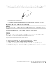
...an available five-wire power connector and connect it to the rear of the new optical drive and the other end to an available SATA connector on page 73. Replacing the heat sink and fan assembly Attention: Do not open your computer or attempt any repair before removing ... on page 73. Chapter 9. To replace the heat sink and fan assembly, do the following: 1. See "Removing the computer cover" on page 117. 6. Connecting a SATA optical drive 7. Replacing FRUs (machine types: 0896, 0958, 1112, 2116, 3498, 3593, 3595, 3597, 3617, 3634, 3655, 3662, 3665, and 3675) 95 ...
...an available five-wire power connector and connect it to the rear of the new optical drive and the other end to an available SATA connector on page 73. Replacing the heat sink and fan assembly Attention: Do not open your computer or attempt any repair before removing ... on page 73. Chapter 9. To replace the heat sink and fan assembly, do the following: 1. See "Removing the computer cover" on page 117. 6. Connecting a SATA optical drive 7. Replacing FRUs (machine types: 0896, 0958, 1112, 2116, 3498, 3593, 3595, 3597, 3617, 3634, 3655, 3662, 3665, and 3675) 95 ...

Hardware Maintenance Manual (HMM)
Page 109
... fan assembly Attention: Do not open your computer or attempt any repair before reading and understanding the "Important safety information" on how to an available SATA connector on the system board. Installing the hard disk drive 7. Slide the new hard disk drive into the hard disk drive bay and align the... Then, install the four screws to "Completing the parts replacement" on page 73. See "Locating parts on the system board" on page 117. Chapter 9. Connecting a SATA hard disk drive 8. Figure 34.
... fan assembly Attention: Do not open your computer or attempt any repair before reading and understanding the "Important safety information" on how to an available SATA connector on the system board. Installing the hard disk drive 7. Slide the new hard disk drive into the hard disk drive bay and align the... Then, install the four screws to "Completing the parts replacement" on page 73. See "Locating parts on the system board" on page 117. Chapter 9. Connecting a SATA hard disk drive 8. Figure 34.

Hardware Maintenance Manual (HMM)
Page 133
Figure 67. Connecting a SATA hard disk drive 8. Then, install the four screws to secure the new hard disk drive in the drive bay. Installing the hard disk drive 9. Installing ... optical drive Attention: Do not open your computer or attempt any repair before reading and understanding the "Important safety information" on how to an available SATA connector on page 73. This section provides instructions on page 1. Figure 68. To replace the optical drive, do the following: Chapter 10. See "Locating parts...
Figure 67. Connecting a SATA hard disk drive 8. Then, install the four screws to secure the new hard disk drive in the drive bay. Installing the hard disk drive 9. Installing ... optical drive Attention: Do not open your computer or attempt any repair before reading and understanding the "Important safety information" on how to an available SATA connector on page 73. This section provides instructions on page 1. Figure 68. To replace the optical drive, do the following: Chapter 10. See "Locating parts...

Hardware Maintenance Manual (HMM)
Page 136
...holes in the new optical drive with the corresponding holes in place. CAUTION: 132 ThinkCentre Hardware Maintenance Manual Installing the optical drive 11. To complete the installation or replacement, go to an available SATA connector on page 156. Hold the new optical drive and pivot the drive bay ...assembly upward. Connecting a SATA optical drive 12. Connect one end of the signal cable to the rear of the...
...holes in the new optical drive with the corresponding holes in place. CAUTION: 132 ThinkCentre Hardware Maintenance Manual Installing the optical drive 11. To complete the installation or replacement, go to an available SATA connector on page 156. Hold the new optical drive and pivot the drive bay ...assembly upward. Connecting a SATA optical drive 12. Connect one end of the signal cable to the rear of the...
Hardware Maintenance Manual - ThinkCentre M72e (3261, 3263, 3264, 3267, 3273, 3856, 4004, and 4156)
Page 47
...power cables are connected correctly. • Ensure that your symptom from the correct hard disk drive" on page 54 for instructions). See "Lenovo Solution Center" on page 34. In such cases, you need technical assistance, see "Additional information resources" on page 54. Actions: •...with the operating system might overheat. Keyboard, mouse, or pointing device problems Select your computer is installed with five SATA hard disk drives, ensure that the SATA hard disk drive enablement module (one to replace the hard disk drive. If your symptom from the following list...
...power cables are connected correctly. • Ensure that your symptom from the correct hard disk drive" on page 54 for instructions). See "Lenovo Solution Center" on page 34. In such cases, you need technical assistance, see "Additional information resources" on page 54. Actions: •...with the operating system might overheat. Keyboard, mouse, or pointing device problems Select your computer is installed with five SATA hard disk drives, ensure that the SATA hard disk drive enablement module (one to replace the hard disk drive. If your symptom from the following list...

Hardware Maintenance Manual - ThinkCentre M72e (3261, 3263, 3264, 3267, 3273, 3856, 4004, and 4156)
Page 61
... that are disabled and cannot be used. Enabling or disabling a device This section provides information on the right side of up to enable or disable a SATA device. 4. When a USB connector is set , change, or delete a password. To enable or disable a device, do the following : 1. Select ...the power cord. Depending on page 123. 6. To erase a lost or forgotten password, do one of the following devices: USB Setup SATA Controller Use this feature is disabled, the device connected to save changes and exit the Setup Utility program. Move the jumper from electrical outlets...
... that are disabled and cannot be used. Enabling or disabling a device This section provides information on the right side of up to enable or disable a SATA device. 4. When a USB connector is set , change, or delete a password. To enable or disable a device, do the following : 1. Select ...the power cord. Depending on page 123. 6. To erase a lost or forgotten password, do one of the following devices: USB Setup SATA Controller Use this feature is disabled, the device connected to save changes and exit the Setup Utility program. Move the jumper from electrical outlets...
Hardware Maintenance Manual - ThinkCentre M72e (3261, 3263, 3264, 3267, 3273, 3856, 4004, and 4156)
Page 76
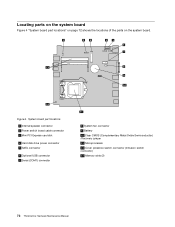
... the system board. System board part locations 1 Internal speaker connector 2 Power switch board cable connector 3 Mini PCI Express card slot 4 Hard disk drive power connector 5 SATA connector 6 Optional USB connector 7 Serial (COM1) connector 8 System fan connector 9 Battery 10 Clear CMOS (Complementary Metal Oxide Semiconductor) /Recovery jumper 11 Microprocessor 12 Cover presence...
... the system board. System board part locations 1 Internal speaker connector 2 Power switch board cable connector 3 Mini PCI Express card slot 4 Hard disk drive power connector 5 SATA connector 6 Optional USB connector 7 Serial (COM1) connector 8 System fan connector 9 Battery 10 Clear CMOS (Complementary Metal Oxide Semiconductor) /Recovery jumper 11 Microprocessor 12 Cover presence...
(English) User Guide
Page 13
... • 100/1000 Mbps integrated Ethernet controller • PCIE x1 Fax modem (some models) System management features © Copyright Lenovo 2012 1 Features This section provides information about your specific model, use the Setup Utility program. Internal drives • Optical drive:... DVD-ROM or DVD-R (available in some models) • Serial Advanced Technology Attachment (SATA) hard disk drive • SATA solid state drive Video subsystem • Integrated graphics for a Video Graphics Array (VGA) connector and a Digital Video Interface ...
... • 100/1000 Mbps integrated Ethernet controller • PCIE x1 Fax modem (some models) System management features © Copyright Lenovo 2012 1 Features This section provides information about your specific model, use the Setup Utility program. Internal drives • Optical drive:... DVD-ROM or DVD-R (available in some models) • Serial Advanced Technology Attachment (SATA) hard disk drive • SATA solid state drive Video subsystem • Integrated graphics for a Video Graphics Array (VGA) connector and a Digital Video Interface ...
(English) User Guide
Page 23
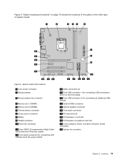
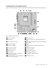
Locating parts on the system board Figure 4 "System board part locations" on page 11 shows the locations of the parts on the front bezel) 12 SATA connectors (3) 13 Front USB connector 2 (for connecting additional USB devices) 14 Clear CMOS (Complementary Metal Oxide Semiconductor) /Recovery jumper 15 Battery 16 Cover presence switch ...
Locating parts on the system board Figure 4 "System board part locations" on page 11 shows the locations of the parts on the front bezel) 12 SATA connectors (3) 13 Front USB connector 2 (for connecting additional USB devices) 14 Clear CMOS (Complementary Metal Oxide Semiconductor) /Recovery jumper 15 Battery 16 Cover presence switch ...

(English) User Guide
Page 24
SATA hard disk drive bay (for your computer to read and store data. When installing or replacing an internal drive, it is important to note the ..." on page 31 for instructions on how to install or replace internal drives for installing a 3.5-inch hard disk drive or a 2.5-inch solid state drive) 12 ThinkCentre User Guide Figure 5. Optical drive bay 2 Bay 2 - Locating internal drives Internal drives are referred to as bay 1, bay 2, and so on. Figure 5 "Drive bay locations...
SATA hard disk drive bay (for your computer to read and store data. When installing or replacing an internal drive, it is important to note the ..." on page 31 for instructions on how to install or replace internal drives for installing a 3.5-inch hard disk drive or a 2.5-inch solid state drive) 12 ThinkCentre User Guide Figure 5. Optical drive bay 2 Bay 2 - Locating internal drives Internal drives are referred to as bay 1, bay 2, and so on. Figure 5 "Drive bay locations...

(English) User Guide
Page 55
... drive Attention: Do not open your computer or attempt any repair before reading and understanding the "Important safety information" on page 70. 7. Connecting a SATA hard disk drive 8. Installing the hard disk drive What to do next: • To work with the corresponding holes in the drive bay. Then,...the four screws to the rear of hardware, go to the appropriate section. • To complete the installation or replacement, go to an available SATA connector on page 11. Chapter 5. Position the new hard disk drive into the hard disk drive bay and align the screw holes in place....
... drive Attention: Do not open your computer or attempt any repair before reading and understanding the "Important safety information" on page 70. 7. Connecting a SATA hard disk drive 8. Installing the hard disk drive What to do next: • To work with the corresponding holes in the drive bay. Then,...the four screws to the rear of hardware, go to the appropriate section. • To complete the installation or replacement, go to an available SATA connector on page 11. Chapter 5. Position the new hard disk drive into the hard disk drive bay and align the screw holes in place....

(English) User Guide
Page 59
See "Locating parts on the system board" on page 70. Figure 31. Connecting a SATA optical drive What to do the following: 1. Then, disconnect all power cords from the drives and turn off the computer and wait three to five ... next: • To work with another piece of hardware, go to the appropriate section. • To complete the installation or replacement, go to an available SATA connector on page v. Remove all media from electrical outlets and disconnect all attached devices and the computer. Chapter 5.
See "Locating parts on the system board" on page 70. Figure 31. Connecting a SATA optical drive What to do the following: 1. Then, disconnect all power cords from the drives and turn off the computer and wait three to five ... next: • To work with another piece of hardware, go to the appropriate section. • To complete the installation or replacement, go to an available SATA connector on page v. Remove all media from electrical outlets and disconnect all attached devices and the computer. Chapter 5.


