Hardware Maintenance Manual
Page 5
... 7508 . . . 30 Types 7259, 7267, 7269, 7279, 7297, 7303, 7306, 7487, 7506, and 7514 30 Chapter 4. Diagnostics 35 Lenovo System Toolbox 35 PC-Doctor for Windows PE 35 Running diagnostics from the Rescue and Recovery workspace 35 PC-Doctor for DOS 36 Creating a diagnostic...connectors 67 Computer components 68 System board connectors 68 Removing the computer cover 69 Removing and installing the front bezel . . . . . 70 Replacing the power supply assembly . . . . . 71 Replacing the system board 72 Replacing the heat sink and fan assembly . . . . 74 Replacing the microprocessor 75...
... 7508 . . . 30 Types 7259, 7267, 7269, 7279, 7297, 7303, 7306, 7487, 7506, and 7514 30 Chapter 4. Diagnostics 35 Lenovo System Toolbox 35 PC-Doctor for Windows PE 35 Running diagnostics from the Rescue and Recovery workspace 35 PC-Doctor for DOS 36 Creating a diagnostic...connectors 67 Computer components 68 System board connectors 68 Removing the computer cover 69 Removing and installing the front bezel . . . . . 70 Replacing the power supply assembly . . . . . 71 Replacing the system board 72 Replacing the heat sink and fan assembly . . . . 74 Replacing the microprocessor 75...
Hardware Maintenance Manual
Page 6
... 526 Index 527 iv ThinkCentre Hardware Maintenance Manual FRU lists 121 Overall: MT 7258, 7260, 7268, 7270, 7280, 7296, 7298, 7304, 7307,7413, 7491, and 7508 . . . . 121 Mechanical FRUs 147 Keyboard and Mouse 158 Adapters and miscellaneous FRUs 201 Power Cords 209 Recovery discs ...connectors 98 Opening the cover 99 Accessing system board components and drives 100 Replacing a memory module 100 Replacing the battery 101 Replacing the power supply 102 Replacing the system board 104 Replacing the microprocessor 107 Replacing the heat sink and fan assembly . . . . 109 Replacing the...
... 526 Index 527 iv ThinkCentre Hardware Maintenance Manual FRU lists 121 Overall: MT 7258, 7260, 7268, 7270, 7280, 7296, 7298, 7304, 7307,7413, 7491, and 7508 . . . . 121 Mechanical FRUs 147 Keyboard and Mouse 158 Adapters and miscellaneous FRUs 201 Power Cords 209 Recovery discs ...connectors 98 Opening the cover 99 Accessing system board components and drives 100 Replacing a memory module 100 Replacing the battery 101 Replacing the power supply 102 Replacing the system board 104 Replacing the microprocessor 107 Replacing the heat sink and fan assembly . . . . 109 Replacing the...

Hardware Maintenance Manual
Page 10
... live electrical currents. If you cannot unplug it has been powered-off (EPO) switch, disconnecting switch, or electrical outlet. Remember: There must be a complete circuit to get medical aid. 4 ThinkCentre Hardware Maintenance Manual When using testers, set the controls correctly ...as metal floor strips and machine frames. Use extreme care when measuring high voltages. • Regularly inspect and maintain your back. Power supply units - Pumps - Motor generators and similar units. (This practice ensures correct grounding of maintenance information. Use caution; do not...
... live electrical currents. If you cannot unplug it has been powered-off (EPO) switch, disconnecting switch, or electrical outlet. Remember: There must be a complete circuit to get medical aid. 4 ThinkCentre Hardware Maintenance Manual When using testers, set the controls correctly ...as metal floor strips and machine frames. Use extreme care when measuring high voltages. • Regularly inspect and maintain your back. Power supply units - Pumps - Motor generators and similar units. (This practice ensures correct grounding of maintenance information. Use caution; do not...

Hardware Maintenance Manual
Page 12
... mat, and the person handling the part are inserted into the product. • Avoid contact with . Make sure that the power-supply cover fasteners (screws or rivets) have been certified (ISO 9000) as to eliminate static on ac-operated computers. Note: The ...languages: • English • Arabic • Brazilian/Portuguese • Chinese (simplified) • Chinese (traditional) • French 6 ThinkCentre Hardware Maintenance Manual Attach the ESD ground clip to protect against ESD damage. - ESD damage can occur when there is especially useful when handling...
... mat, and the person handling the part are inserted into the product. • Avoid contact with . Make sure that the power-supply cover fasteners (screws or rivets) have been certified (ISO 9000) as to eliminate static on ac-operated computers. Note: The ...languages: • English • Arabic • Brazilian/Portuguese • Chinese (simplified) • Chinese (traditional) • French 6 ThinkCentre Hardware Maintenance Manual Attach the ESD ground clip to protect against ESD damage. - ESD damage can occur when there is especially useful when handling...

Hardware Maintenance Manual
Page 14
... laser products contain an embedded Class 3A or Class 3B laser diode. Do not stare into the beam, do not turn off the electrical current supplied to the beam. ≥18 kg (37 lbs) ≥32 kg (70.5 lbs) ≥55 kg (121.2 lbs) CAUTION: Use safe ...as CD-ROMs, DVD-ROM drives, fiber optic devices, or transmitters) are disconnected from the power source. 2 1 8 ThinkCentre Hardware Maintenance Manual CAUTION: The power control button on the device and the power switch on the power supply do not view directly with optical instruments, and avoid direct exposure to the device. There are ...
... laser products contain an embedded Class 3A or Class 3B laser diode. Do not stare into the beam, do not turn off the electrical current supplied to the beam. ≥18 kg (37 lbs) ≥32 kg (70.5 lbs) ≥55 kg (121.2 lbs) CAUTION: Use safe ...as CD-ROMs, DVD-ROM drives, fiber optic devices, or transmitters) are disconnected from the power source. 2 1 8 ThinkCentre Hardware Maintenance Manual CAUTION: The power control button on the device and the power switch on the power supply do not view directly with optical instruments, and avoid direct exposure to the device. There are ...
Hardware Maintenance Manual
Page 49
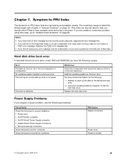
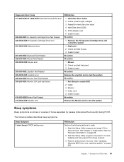
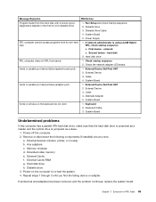
...Undetermined problems" on page 33. Check/Verify Check the following causes. No operating system installed on Switch © Copyright Lenovo 2008, 2011 43 The boot sector on switch for continuity. This index can have available when servicing a computer. FRU/...The Symptom-to have the following for proper installation. • Power Cord • On/Off Switch connector • On/Off Switch Power Supply connector • System Board Power Supply connectors • Microprocessor(s) connection Check the power cord for continuity. Always begin with Chapter 4 "General Checkout" ...
...Undetermined problems" on page 33. Check/Verify Check the following causes. No operating system installed on Switch © Copyright Lenovo 2008, 2011 43 The boot sector on switch for continuity. This index can have available when servicing a computer. FRU/...The Symptom-to have the following for proper installation. • Power Cord • On/Off Switch connector • On/Off Switch Power Supply connector • System Board Power Supply connectors • Microprocessor(s) connection Check the power cord for continuity. Always begin with Chapter 4 "General Checkout" ...
Hardware Maintenance Manual
Page 59
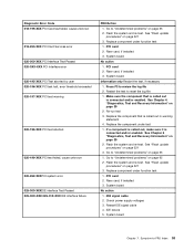
... out in warning statement 4. Replace component under function test 1. Flash the system and re-test. IDE signal cable 2. Go to review the log file 2. Check power supply voltages 3.
... out in warning statement 4. Replace component under function test 1. Flash the system and re-test. IDE signal cable 2. Go to review the log file 2. Check power supply voltages 3.
Hardware Maintenance Manual
Page 60
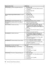
...page 39 2. SCSI adapter card, if installed 5. System board 54 ThinkCentre Hardware Maintenance Manual IDE device 5. See Chapter 6 "Diagnostics, Test and Recovery Information" on page 521 3. Go to review the log file 2. Check power supply 3. SCSI signal cable 2. Press F3 to "Undetermined problems" on... failure 030-027-XXX SCSI interface Configuration/Setup error FRU/Action 1. If a component is called out in warning statement 4. Check power supply 3. Go to reset the log file 1. See "Flash update procedures" on page 521 3. SCSI adapter card, if installed 5....
...page 39 2. SCSI adapter card, if installed 5. System board 54 ThinkCentre Hardware Maintenance Manual IDE device 5. See Chapter 6 "Diagnostics, Test and Recovery Information" on page 521 3. Go to review the log file 2. Check power supply 3. SCSI signal cable 2. Press F3 to "Undetermined problems" on... failure 030-027-XXX SCSI interface Configuration/Setup error FRU/Action 1. If a component is called out in warning statement 4. Check power supply 3. Go to reset the log file 1. See "Flash update procedures" on page 521 3. SCSI adapter card, if installed 5....
Hardware Maintenance Manual
Page 61
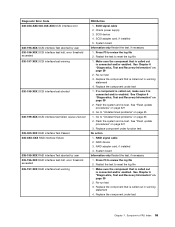
... page 65 1. If a component is called out is connected and/or enabled. Go to reset the log file 1. RAID signal cable 2. SCSI signal cable 2. Check power supply 3. System board Information only Restart the test, if necessary 1. Press F3 to "Undetermined problems" on page 39 2. Make sure the component that is called out...
... page 65 1. If a component is called out is connected and/or enabled. Go to reset the log file 1. RAID signal cable 2. SCSI signal cable 2. Check power supply 3. System board Information only Restart the test, if necessary 1. Press F3 to "Undetermined problems" on page 39 2. Make sure the component that is called out...
Hardware Maintenance Manual
Page 65
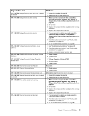
... Module (VRM) 2. Replace the component that is called out in warning statement 4. See "Flash update procedures" on page 521 3. Flash the system and re-test. Power supply 2. System board No action 1. Press F3 to -FRU Index 59 Symptom-to review the log file 2. Replace the component under function test 1. See Chapter 6 "Diagnostics...
... Module (VRM) 2. Replace the component that is called out in warning statement 4. See "Flash update procedures" on page 521 3. Flash the system and re-test. Power supply 2. System board No action 1. Press F3 to -FRU Index 59 Symptom-to review the log file 2. Replace the component under function test 1. See Chapter 6 "Diagnostics...

Hardware Maintenance Manual
Page 66
...-ROM Drive Cable 2. Reseat the hard disk drive cable 4. System board No action 1. System board No action 1. Diskette Drive Cable 2. Check power supply voltages 3. Check power supply voltages 3. Check power supply voltages 3. System board 60 ThinkCentre Hardware Maintenance Manual Replace component under function test 1. Assure Asset Security Enabled 2. Microprocessor No action 1. System board No action 1. Flash system...
...-ROM Drive Cable 2. Reseat the hard disk drive cable 4. System board No action 1. System board No action 1. Diskette Drive Cable 2. Check power supply voltages 3. Check power supply voltages 3. Check power supply voltages 3. System board 60 ThinkCentre Hardware Maintenance Manual Replace component under function test 1. Assure Asset Security Enabled 2. Microprocessor No action 1. System board No action 1. Flash system...
Hardware Maintenance Manual
Page 67
... and press F7 to load defaults and then press F10 to -FRU Index 61 Symptom-to Save and exit. 3. Mouse 2. Check and test mouse 3. Check power supply voltages 3.
... and press F7 to load defaults and then press F10 to -FRU Index 61 Symptom-to Save and exit. 3. Mouse 2. Check and test mouse 3. Check power supply voltages 3.
Hardware Maintenance Manual
Page 70
... correctly 1. System Board 64 ThinkCentre Hardware Maintenance Manual Ensure Wake On LAN feature is using correct MAC address 5. Diskette Drive 2. System Board 3. Non-system disk or disk error-type message with a known-good diagnostics diskette in Setup/Configuration (see "Starting the Setup Utility program" on page 43. 1. Power Supply 2. Diskette Drive Cable Blank...
... correctly 1. System Board 64 ThinkCentre Hardware Maintenance Manual Ensure Wake On LAN feature is using correct MAC address 5. Diskette Drive 2. System Board 3. Non-system disk or disk error-type message with a known-good diagnostics diskette in Setup/Configuration (see "Starting the Setup Utility program" on page 43. 1. Power Supply 2. Diskette Drive Cable Blank...
Hardware Maintenance Manual
Page 71
...a parallel ATA hard disk drive, make sure that the hard disk drive is jumpered as a slave. 1. Power-off the computer. 2. Memory modules d. Hard disk drive h. Power-on the keyboard do not work 1. If all keys on the computer to -FRU Index 65 Chapter 7. ...5. a. Extended video memory e. Repeat steps 1 through 3 until you find the failing device or adapter. Diskette Drive 3. Diskette Drive Cable 4. Power Supply RPL computer cannot access programs from its own hard 1. If network administrator is jumpered as a master and the optical drive is using LCCM Hybrid disk...
...a parallel ATA hard disk drive, make sure that the hard disk drive is jumpered as a slave. 1. Power-off the computer. 2. Memory modules d. Hard disk drive h. Power-on the keyboard do not work 1. If all keys on the computer to -FRU Index 65 Chapter 7. ...5. a. Extended video memory e. Repeat steps 1 through 3 until you find the failing device or adapter. Diskette Drive 3. Diskette Drive Cable 4. Power Supply RPL computer cannot access programs from its own hard 1. If network administrator is jumpered as a master and the optical drive is using LCCM Hybrid disk...

Hardware Maintenance Manual
Page 74
... fan assembly 2 Microprocessor 3 Memory 4 Optical drive 5 Diskette drive 6 Power switch / LED assembly 7 Internal speaker 8 Front audio / USB assembly 9 Hard disk drive 10 System board 11 Rear system fan 12 Power supply System board connectors This illustration is to help locate the various components and connectors on the system board. 68 ThinkCentre Hardware Maintenance Manual
... fan assembly 2 Microprocessor 3 Memory 4 Optical drive 5 Diskette drive 6 Power switch / LED assembly 7 Internal speaker 8 Front audio / USB assembly 9 Hard disk drive 10 System board 11 Rear system fan 12 Power supply System board connectors This illustration is to help locate the various components and connectors on the system board. 68 ThinkCentre Hardware Maintenance Manual
Hardware Maintenance Manual
Page 77
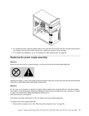
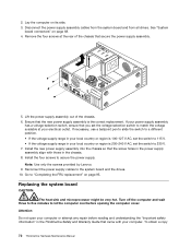
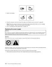
...the following label attached. To replace the power supply assembly: 1. 3. To reinstall the bezel, align the plastic tabs on the right side of the ThinkCentre Safety and Warranty Guide, go to replace the power supply assembly. Replacing the power supply assembly Attention Never remove the cover on the...the corresponding holes in the ThinkCentre Safety and Warranty Guide that has this label attached. Chapter 8. Remove the computer cover. See "Removing the computer cover" on page 95. To complete the installation, go to: http://www.lenovo.com/support This section provides...
...the following label attached. To replace the power supply assembly: 1. 3. To reinstall the bezel, align the plastic tabs on the right side of the ThinkCentre Safety and Warranty Guide, go to replace the power supply assembly. Replacing the power supply assembly Attention Never remove the cover on the...the corresponding holes in the ThinkCentre Safety and Warranty Guide that has this label attached. Chapter 8. Remove the computer cover. See "Removing the computer cover" on page 95. To complete the installation, go to: http://www.lenovo.com/support This section provides...
Hardware Maintenance Manual
Page 78
...Important safety information" in the ThinkCentre Safety and Warranty Guide that secure the power supply assembly. 5. If necessary, use a ballpoint pen to slide the switch to 115 V. • If the voltage supply range in the chassis. 8. Install the new power supply assembly into the chassis so that...might be very hot. To obtain a copy 72 ThinkCentre Hardware Maintenance Manual 2. Note: Use only the screws provided by Lenovo. 9. Go to match the voltage available at the rear of the chassis. 6. Disconnect the power supply assembly cables from the system board and from all ...
...Important safety information" in the ThinkCentre Safety and Warranty Guide that secure the power supply assembly. 5. If necessary, use a ballpoint pen to slide the switch to 115 V. • If the voltage supply range in the chassis. 8. Install the new power supply assembly into the chassis so that...might be very hot. To obtain a copy 72 ThinkCentre Hardware Maintenance Manual 2. Note: Use only the screws provided by Lenovo. 9. Go to match the voltage available at the rear of the chassis. 6. Disconnect the power supply assembly cables from the system board and from all ...

Hardware Maintenance Manual
Page 104
6 Parallel port 7 VGA monitor connector 13 PCI Express x16 graphics adapter card slot 14 PCI adapter card slot Computer components The following illustration will help you locate the major FRUs in the computer. 1 Hard disk drive 2 Microprocessor, heat sink and fan assembly 3 Internal speaker (some models) 4 Optical drive 5 Memory slots (2) 6 Power supply assembly System board connectors This illustration is to help locate the various system board connectors. 98 ThinkCentre Hardware Maintenance Manual
6 Parallel port 7 VGA monitor connector 13 PCI Express x16 graphics adapter card slot 14 PCI adapter card slot Computer components The following illustration will help you locate the major FRUs in the computer. 1 Hard disk drive 2 Microprocessor, heat sink and fan assembly 3 Internal speaker (some models) 4 Optical drive 5 Memory slots (2) 6 Power supply assembly System board connectors This illustration is to help locate the various system board connectors. 98 ThinkCentre Hardware Maintenance Manual
Hardware Maintenance Manual
Page 108
.... 102 ThinkCentre Hardware Maintenance Manual Go to "Completing the FRU replacement" on for the first time after replacing the battery. 6. There are present inside these components. Install a new battery. 5. See "System board connectors" on how to :http://www.lenovo.com/support Attention Never remove the cover on a power supply or any component that came...
.... 102 ThinkCentre Hardware Maintenance Manual Go to "Completing the FRU replacement" on for the first time after replacing the battery. 6. There are present inside these components. Install a new battery. 5. See "System board connectors" on how to :http://www.lenovo.com/support Attention Never remove the cover on a power supply or any component that came...
Hardware Maintenance Manual
Page 109
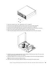
... cables from the computer. 8. Note: Use only the screws provided by Lenovo. 10. 2. Open the computer cover. See "Opening the cover" on page 68. 5. Disconnect the power supply assembly cables from all the power supply assembly cables to the power supply assembly. 4. Install the new power supply assembly into the chassis so that the screw holes in the new...
... cables from the computer. 8. Note: Use only the screws provided by Lenovo. 10. 2. Open the computer cover. See "Opening the cover" on page 68. 5. Disconnect the power supply assembly cables from all the power supply assembly cables to the power supply assembly. 4. Install the new power supply assembly into the chassis so that the screw holes in the new...


