
User Manual
Page 7
... for damage, wear, or signs of danger. However, do not use your computer. Frequently inspect your purchase agreement or the Lenovo™ Limited Warranty. For more information, refer to the safety and warranty information that provides power to be used again until ... a safer computer work environment. Contact the Customer Support Center for instructions on the product and in the operating instructions, and review the information included in physical injury or property damage, especially if misused. Important safety information Note Please read important safety information first...
... for damage, wear, or signs of danger. However, do not use your computer. Frequently inspect your purchase agreement or the Lenovo™ Limited Warranty. For more information, refer to the safety and warranty information that provides power to be used again until ... a safer computer work environment. Contact the Customer Support Center for instructions on the product and in the operating instructions, and review the information included in physical injury or property damage, especially if misused. Important safety information Note Please read important safety information first...

User Manual
Page 77
...Depending upon your machine type and model, you either have PC-Doctor for DOS or PC-Doctor for computer problems, access the Lenovo troubleshooting center, update system drivers, and review system information. Note: Be sure to create a diagnostic CD image or diagnostic diskettes in isolating a possible problem. Chapter 7....Doctor for Windows PE to help system. If you are unable to run PC-Doctor for Windows, open the Start menu from http://www.lenovo.com/support/ onto two blank, formatted diskettes. If your computer does not have a CD burner or you do not have Internet access, ...
...Depending upon your machine type and model, you either have PC-Doctor for DOS or PC-Doctor for computer problems, access the Lenovo troubleshooting center, update system drivers, and review system information. Note: Be sure to create a diagnostic CD image or diagnostic diskettes in isolating a possible problem. Chapter 7....Doctor for Windows PE to help system. If you are unable to run PC-Doctor for Windows, open the Start menu from http://www.lenovo.com/support/ onto two blank, formatted diskettes. If your computer does not have a CD burner or you do not have Internet access, ...
Hardware Maintenance Manual
Page 49
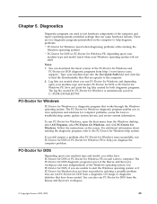
...Programs, select PC-Doctor for Windows, and click PC-Doctor for DOS diagnostic programs from the Rescue and Recovery workspace. © Copyright Lenovo 2005, 2008 43 To run PC-Doctor for Windows, open the Start menu from a diagnostic CD image or diagnostic diskettes that works ... Windows is a diagnostic program that have PC-Doctor for DOS or PC-Doctor for computer problems, access the Lenovo troubleshooting center, update system drivers, and review system information. You can download the latest version of the computer and report operating-system-controlled settings that are ...
...Programs, select PC-Doctor for Windows, and click PC-Doctor for DOS diagnostic programs from the Rescue and Recovery workspace. © Copyright Lenovo 2005, 2008 43 To run PC-Doctor for Windows, open the Start menu from a diagnostic CD image or diagnostic diskettes that works ... Windows is a diagnostic program that have PC-Doctor for DOS or PC-Doctor for computer problems, access the Lenovo troubleshooting center, update system drivers, and review system information. You can download the latest version of the computer and report operating-system-controlled settings that are ...
Hardware Maintenance Manual
Page 64
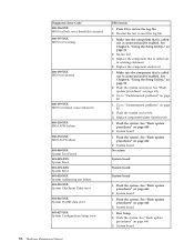
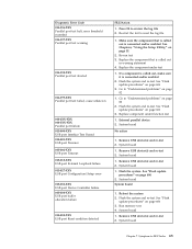
... page 51 2. Replace the component that is called out is called out in warning statement 4. Flash the system and retest. Re-start the test to review the log file 2. See Chapter 6, "Using the Setup Utility," on page 606 3. See "Flash update procedures" on page 606 2. See "Flash update procedures" on page...
... page 51 2. Replace the component that is called out is called out in warning statement 4. Flash the system and retest. Re-start the test to review the log file 2. See Chapter 6, "Using the Setup Utility," on page 606 3. See "Flash update procedures" on page 606 2. See "Flash update procedures" on page...

Hardware Maintenance Manual
Page 65
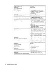
... test 4. Flash the system. Power-off /on system and re-test 2. Re-run test 3. See Chapter 6, "Using the Setup Utility," on page 606 3. Go to review the log file 2. See "Flash update procedures" on page 51 2. System board 1. Press F3 to "Undetermined problems" on system and re-test 2. Replace component under...
... test 4. Flash the system. Power-off /on system and re-test 2. Re-run test 3. See Chapter 6, "Using the Setup Utility," on page 606 3. Go to review the log file 2. See "Flash update procedures" on page 51 2. System board 1. Press F3 to "Undetermined problems" on system and re-test 2. Replace component under...
Hardware Maintenance Manual
Page 68
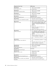
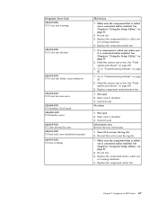
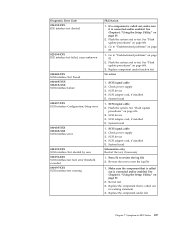
...006-196-XXX Diskette interface test halt, error threshold exceeded FRU/Action 1. Flash the system and re-test. Replace component under test 1. Press F3 to review the log file 2. Video card, if installed 2. System board Information only Re-start the test to reset the log file 62 Hardware Maintenance Manual Diskette... drive 3. See Chapter 6, "Using the Setup Utility," on page 606 3. System board No action 1. Press F3 to review the log file 2. If a component is called out in warning statement 4. System board 1.
...006-196-XXX Diskette interface test halt, error threshold exceeded FRU/Action 1. Flash the system and re-test. Replace component under test 1. Press F3 to review the log file 2. Video card, if installed 2. System board Information only Re-start the test to reset the log file 62 Hardware Maintenance Manual Diskette... drive 3. See Chapter 6, "Using the Setup Utility," on page 606 3. System board No action 1. Press F3 to review the log file 2. If a component is called out in warning statement 4. System board 1.

Hardware Maintenance Manual
Page 69
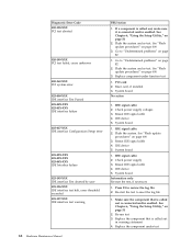
... System board 011-195-XXX Serial port Test aborted by user Information only Re-start the test to reset the log file Chapter 7. Symptom-to review the log file Serial port test halt, error threshold exceeded 2. Flash the system and re-test. Flash the system and re-test 3. System board 011...
... System board 011-195-XXX Serial port Test aborted by user Information only Re-start the test to reset the log file Chapter 7. Symptom-to review the log file Serial port test halt, error threshold exceeded 2. Flash the system and re-test. Flash the system and re-test 3. System board 011...
Hardware Maintenance Manual
Page 71
Press F3 to "Undetermined problems" on page 82 2. Re-run test 3. Flash the system and re-test. Go to review the log file 2. Replace component under test 1. Remove USB device(s) and re-test 2. Remove USB device(s) and re-test 2. Run memory test 4. Re-start the ...
Press F3 to "Undetermined problems" on page 82 2. Re-run test 3. Flash the system and re-test. Go to review the log file 2. Replace component under test 1. Remove USB device(s) and re-test 2. Remove USB device(s) and re-test 2. Run memory test 4. Re-start the ...
Hardware Maintenance Manual
Page 72
... Hardware Maintenance Manual Press F3 to "Undetermined problems" on page 82 1. See Chapter 6, "Using the Setup Utility," on page 606 3. Go to review the log file 2. Go to review the log file 2. Replace component under test 1. PCI card 2. Make sure the component that is connected and/or enabled. Flash the system and...
... Hardware Maintenance Manual Press F3 to "Undetermined problems" on page 82 1. See Chapter 6, "Using the Setup Utility," on page 606 3. Go to review the log file 2. Go to review the log file 2. Replace component under test 1. PCI card 2. Make sure the component that is connected and/or enabled. Flash the system and...
Hardware Maintenance Manual
Page 73
... 2. Press F3 to -FRU Index 67 If a component is called out in warning statement 4. Replace component under test Chapter 7. PCI card 2. PCI card 2. Symptom-to review the log file 2. Flash the system and re-test. Make sure the component that is called out is connected and/or enabled. Replace the component...
... 2. Press F3 to -FRU Index 67 If a component is called out in warning statement 4. Replace component under test Chapter 7. PCI card 2. PCI card 2. Symptom-to review the log file 2. Flash the system and re-test. Make sure the component that is called out is connected and/or enabled. Replace the component...
Hardware Maintenance Manual
Page 74
... component under test Check power supply 3. Press F3 to "Undetermined problems" on page 51 2. See Chapter 6, "Using the Setup Utility," on page 82 1. Go to review the log file 2. Check power supply voltages 3. IDE signal cable 2. Reseat IDE signal cable 4. If a component is connected and/or enabled. See Chapter 6, "Using the...
... component under test Check power supply 3. Press F3 to "Undetermined problems" on page 51 2. See Chapter 6, "Using the Setup Utility," on page 82 1. Go to review the log file 2. Check power supply voltages 3. IDE signal cable 2. Reseat IDE signal cable 4. If a component is connected and/or enabled. See Chapter 6, "Using the...
Hardware Maintenance Manual
Page 75
... "Flash update procedures" on page 51 2. SCSI adapter card, if installed 5. System board 1. Check power supply 3. System board Information only Re-start the test to review the log file 2. See Chapter 6, "Using the Setup Utility," on page 606 3. Go to "Undetermined problems" on page 82 1. Check power supply 3. SCSI device 4. SCSI...
... "Flash update procedures" on page 51 2. SCSI adapter card, if installed 5. System board 1. Check power supply 3. System board Information only Re-start the test to review the log file 2. See Chapter 6, "Using the Setup Utility," on page 606 3. Go to "Undetermined problems" on page 82 1. Check power supply 3. SCSI device 4. SCSI...

Hardware Maintenance Manual
Page 76
.../or enabled. Press F3 to "Undetermined problems" on page 82 2. If a component is called out, make sure it is connected and/or enabled. Go to review the log file 2. See Chapter 6, "Using the Setup Utility," on page 51 2. Flash the system and re-test. Diagnostic Error Code 030-198-XXX SCSI...
.../or enabled. Press F3 to "Undetermined problems" on page 82 2. If a component is called out, make sure it is connected and/or enabled. Go to review the log file 2. See Chapter 6, "Using the Setup Utility," on page 51 2. Flash the system and re-test. Diagnostic Error Code 030-198-XXX SCSI...
Hardware Maintenance Manual
Page 77
... necessary Chapter 7. Re-start the test to -FRU Index 71 Re-run test 3. If a component is called out is connected and/or enabled. Go to review the log file 2. Flash the system and re-test. Symptom-to reset the log file 1. Run Setup 2. System board 1. Run Setup 2. Make sure the component...
... necessary Chapter 7. Re-start the test to -FRU Index 71 Re-run test 3. If a component is called out is connected and/or enabled. Go to review the log file 2. Flash the system and re-test. Symptom-to reset the log file 1. Run Setup 2. System board 1. Run Setup 2. Make sure the component...

Hardware Maintenance Manual
Page 78
Re-start the test to review the log file Game Port interface test halt, error threshold exceeded 2. Flash the system and re-test. Go to "Undetermined problems" on page 82 2. System ... 2. Flash the system and re-test. System board 086-195-XXX Mouse Port interface Test aborted by user Information only Re-start the test to review the log file 2. Press F3 to reset the log file 72 Hardware Maintenance Manual Re-start the test, if necessary 086-196-XXX Mouse Port...
Re-start the test to review the log file Game Port interface test halt, error threshold exceeded 2. Flash the system and re-test. Go to "Undetermined problems" on page 82 2. System ... 2. Flash the system and re-test. System board 086-195-XXX Mouse Port interface Test aborted by user Information only Re-start the test to review the log file 2. Press F3 to reset the log file 72 Hardware Maintenance Manual Re-start the test, if necessary 086-196-XXX Mouse Port...

Hardware Maintenance Manual
Page 79
... the test, if necessary 1. Make sure the component that is connected and/or enabled. Replace the component under function test No action Chapter 7. Symptom-to review the log file 2. Make sure the component that is called out is connected and/or enabled. Re-run test 3. See "Flash update procedures" on page...
... the test, if necessary 1. Make sure the component that is connected and/or enabled. Replace the component under function test No action Chapter 7. Symptom-to review the log file 2. Make sure the component that is called out is connected and/or enabled. Re-run test 3. See "Flash update procedures" on page...

Hardware Maintenance Manual
Page 80
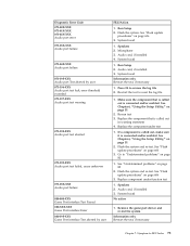
... procedures" on page 51 2. Microprocessor 3. Flash system 2. System board 175-195-XXX Thermal Sensor(s) Test aborted by user Information only Re-start the test to review the log file 2. System board 175-000-XXX Thermal Sensor(s) Test Passed No action 175-0XX-XXX Thermal Sensor(s) failure 1. Flash system 2. Replace the component... and re-test. See "Undetermined problems" on page 82 170-199-XXX Voltage Sensor(s) test failed, cause unknown 1. Voltage Regulator Module (VRM) 2. Press F3 to review the log file 2.
... procedures" on page 51 2. Microprocessor 3. Flash system 2. System board 175-195-XXX Thermal Sensor(s) Test aborted by user Information only Re-start the test to review the log file 2. System board 175-000-XXX Thermal Sensor(s) Test Passed No action 175-0XX-XXX Thermal Sensor(s) failure 1. Flash system 2. Replace the component... and re-test. See "Undetermined problems" on page 82 170-199-XXX Voltage Sensor(s) test failed, cause unknown 1. Voltage Regulator Module (VRM) 2. Press F3 to review the log file 2.

