Hardware Maintenance Manual
Page 5
...Power management 22 Checkout guide 24 Testing the computer 24 Detecting system information with PC-Doctor . . 26 Power system checkout 26 Lenovo 3000 N200 29 Product overview 30 Specifications 30 Status indicators 32 FRU tests 33 Fn key combinations 34 Symptom-to-FRU index 35 Numeric error... assembly 53 1110 CPU 55 1120 Middle cover and function board . . . . 56 1130 Keyboard 58 1140 Keyboard bezel and fingerprint reader card 60 1150 Backup battery 64 1160 Modem daughter card (MDC) . . . . . 65 1170 Bluetooth daughter card (BDC) . . . . . 66 1180 LCD unit 67 1190 System board, ...
...Power management 22 Checkout guide 24 Testing the computer 24 Detecting system information with PC-Doctor . . 26 Power system checkout 26 Lenovo 3000 N200 29 Product overview 30 Specifications 30 Status indicators 32 FRU tests 33 Fn key combinations 34 Symptom-to-FRU index 35 Numeric error... assembly 53 1110 CPU 55 1120 Middle cover and function board . . . . 56 1130 Keyboard 58 1140 Keyboard bezel and fingerprint reader card 60 1150 Backup battery 64 1160 Modem daughter card (MDC) . . . . . 65 1170 Bluetooth daughter card (BDC) . . . . . 66 1180 LCD unit 67 1190 System board, ...

Hardware Maintenance Manual
Page 20
... operator safety and correct system function. v Select a grounding system, such as fully effective. Attach the ESD ground clip to eliminate static on a double-insulated or battery-operated system, use have been certified (ISO 9000) as those listed below, to provide a static-free work mat, and the person handling the part are...
... operator safety and correct system function. v Select a grounding system, such as fully effective. Attach the ESD ground clip to eliminate static on a double-insulated or battery-operated system, use have been certified (ISO 9000) as those listed below, to provide a static-free work mat, and the person handling the part are...

Hardware Maintenance Manual
Page 27
...menu marked *1 is displayed. 3. then, while the initial screen is displayed, press the Lenovo CareSM button. then leave the Enter New Password field blank, and press Enter twice. 9. Remove the backup battery. The POP has been removed. 5. Select Password. 6. then, while the initial screen ...is displayed, press the Lenovo Care button. Click Yes. In the Changes have forgotten, do the following : (A)...
...menu marked *1 is displayed. 3. then, while the initial screen is displayed, press the Lenovo CareSM button. then leave the Enter New Password field blank, and press Enter twice. 9. Remove the backup battery. The POP has been removed. 5. Select Password. 6. then, while the initial screen ...is displayed, press the Lenovo Care button. Click Yes. In the Changes have forgotten, do the following : (A)...

Hardware Maintenance Manual
Page 28
... a "suspend time" has been set on the timer, and the user does not do any of the following: v Press the Fn key. v If the battery indicator blinks orange, indicating that time. Wait a few seconds before taking any key. v The system is powered off . v Turn on the "Turn off ....Note: The computer does not accept any operation with the keyboard, the hard disk, the parallel connector, or the diskette drive within that the battery power is powered off. To reduce power consumption, the computer has three power management modes: screen blank, sleep (standby), and hibernation. Select ...
... a "suspend time" has been set on the timer, and the user does not do any of the following: v Press the Fn key. v If the battery indicator blinks orange, indicating that time. Wait a few seconds before taking any key. v The system is powered off . v Turn on the "Turn off ....Note: The computer does not accept any operation with the keyboard, the hard disk, the parallel connector, or the diskette drive within that the battery power is powered off. To reduce power consumption, the computer has three power management modes: screen blank, sleep (standby), and hibernation. Select ...

Hardware Maintenance Manual
Page 32
...power is designed to help you troubleshoot and resolve problems related to display symptoms and solutions: v CHECK SYSTEM HEALTH v SYSTEM AND DEVICE TESTS v LENOVO TROUBLESHOOTING v CENTER v SYSTEM REPORTS v UPDATES AND SUPPORT Power system checkout To verify a symptom, do the following power supply checkouts: v "...VESA LCD Info v Hardware Events Log Utility v Run External Tests v Surface Scan Hard Disk v Benchmark System v DOS Shell v Tech Support Form v Battery Rundown v View Test Log v Print Log v Save Log v Full Erase Hard Drive v Quick Erase Hard Drive PC-Doctor for Windows This product ...
...power is designed to help you troubleshoot and resolve problems related to display symptoms and solutions: v CHECK SYSTEM HEALTH v SYSTEM AND DEVICE TESTS v LENOVO TROUBLESHOOTING v CENTER v SYSTEM REPORTS v UPDATES AND SUPPORT Power system checkout To verify a symptom, do the following power supply checkouts: v "...VESA LCD Info v Hardware Events Log Utility v Run External Tests v Surface Scan Hard Disk v Benchmark System v DOS Shell v Tech Support Form v Battery Rundown v View Test Log v Print Log v Save Log v Full Erase Hard Drive v Quick Erase Hard Drive PC-Doctor for Windows This product ...

Hardware Maintenance Manual
Page 33
...output voltage at the plug of its capacity. General descriptions 27 If the charge indicator or icon still does not turn on , replace the battery pack. v If the problem persists, go to the Power Meter icon in the computer. If the charge indicator still does not turn on...acceptable, do the following : v Replace the system board. If the battery status indicator or icon does not turn on , remove the battery pack and let it is used. Then reinstall the battery pack. Checking the battery pack Battery charging does not start until the Power Meter shows that has less ...
...output voltage at the plug of its capacity. General descriptions 27 If the charge indicator or icon still does not turn on , replace the battery pack. v If the problem persists, go to the Power Meter icon in the computer. If the charge indicator still does not turn on...acceptable, do the following : v Replace the system board. If the battery status indicator or icon does not turn on , remove the battery pack and let it is used. Then reinstall the battery pack. Checking the battery pack Battery charging does not start until the Power Meter shows that has less ...

Hardware Maintenance Manual
Page 34
... becomes hot, it may not be 4 to 30 K . See the following : 1. If the voltage is not correct, replace the battery pack. After it cools down, reinstall and recharge it at least 3 hours, even if the indicator does not turn on. If the ... 7 (−). If the voltage is less than +11.0 V dc after recharging, replace the battery. 4. Power off the computer. 2. Note: Recharging will take at room temperature for a while. Remove the battery pack and measure the voltage between battery terminals 4 and 7. Remove it from the computer and leave it . If the voltage is still...
... becomes hot, it may not be 4 to 30 K . See the following : 1. If the voltage is not correct, replace the battery pack. After it cools down, reinstall and recharge it at least 3 hours, even if the indicator does not turn on. If the ... 7 (−). If the voltage is less than +11.0 V dc after recharging, replace the battery. 4. Power off the computer. 2. Note: Recharging will take at room temperature for a while. Remove the battery pack and measure the voltage between battery terminals 4 and 7. Remove it from the computer and leave it . If the voltage is still...

Hardware Maintenance Manual
Page 35
Lenovo 3000 N200 Product overview 30 Specifications 30 Status indicators 32 FRU tests 33 Fn key combinations...42 Retaining the UUID 42 Reading or writing the ECA information . . 42 Removing and replacing a FRU 44 1010 Battery pack 45 1020 Hard disk drive slot cover 46 1030 Hard disk drive 46 1040 DIMM slot cover 47 1050 ... 53 1110 CPU 55 1120 Middle cover and function board . . . . 56 1130 Keyboard 58 1140 Keyboard bezel and fingerprint reader card 60 1150 Backup battery 64 1160 Modem daughter card (MDC) . . . . . 65 1170 Bluetooth daughter card (BDC) . . . . . 66 1180 LCD unit ...
Lenovo 3000 N200 Product overview 30 Specifications 30 Status indicators 32 FRU tests 33 Fn key combinations...42 Retaining the UUID 42 Reading or writing the ECA information . . 42 Removing and replacing a FRU 44 1010 Battery pack 45 1020 Hard disk drive slot cover 46 1030 Hard disk drive 46 1040 DIMM slot cover 47 1050 ... 53 1110 CPU 55 1120 Middle cover and function board . . . . 56 1130 Keyboard 58 1140 Keyboard bezel and fingerprint reader card 60 1150 Backup battery 64 1160 Modem daughter card (MDC) . . . . . 65 1170 Bluetooth daughter card (BDC) . . . . . 66 1180 LCD unit ...

Hardware Maintenance Manual
Page 37
...the system board) Mini PCI adapter ExpressCard slot Bluetooth wireless (some models) Modem Touch pad Battery AC adapter Preinstalled operating system Description v 5-1 Digital Media Reader v External monitor connector v ...PRO Wireless 3945ABG Mini-PCI Express Adapter v Broadcom 802.11bg WLAN PCI-E Mini Card v Lenovo 11a/b/g/n Wireless LAN Mini-PCI Express Adapter v Intel Wireless WiFi Link 4965AGN v ExpressCard slot v ...Bluetooth daughter card v AMoM, 56 kbps V.92 Yes v Li-ion battery (6 cells) 2.4 Ah v 65-watt (20 V) slim type v 90-watt (20 V) type v ...
...the system board) Mini PCI adapter ExpressCard slot Bluetooth wireless (some models) Modem Touch pad Battery AC adapter Preinstalled operating system Description v 5-1 Digital Media Reader v External monitor connector v ...PRO Wireless 3945ABG Mini-PCI Express Adapter v Broadcom 802.11bg WLAN PCI-E Mini Card v Lenovo 11a/b/g/n Wireless LAN Mini-PCI Express Adapter v Intel Wireless WiFi Link 4965AGN v ExpressCard slot v ...Bluetooth daughter card v AMoM, 56 kbps V.92 Yes v Li-ion battery (6 cells) 2.4 Ah v 65-watt (20 V) slim type v 90-watt (20 V) type v ...

Hardware Maintenance Manual
Page 39
... (standby) mode. Interactive Tests --> Video 1. If the problem does not recur, return the DIMM to 20% of the capacity, and being discharged. Lenovo 3000 N200 33 Blinking orange (slow): The battery is charged between 80% to 80% of the capacity. FRU tests The following table shows the test for use. Diagnostics --> Video Adapter...
... (standby) mode. Interactive Tests --> Video 1. If the problem does not recur, return the DIMM to 20% of the capacity, and being discharged. Lenovo 3000 N200 33 Blinking orange (slow): The battery is charged between 80% to 80% of the capacity. FRU tests The following table shows the test for use. Diagnostics --> Video Adapter...

Hardware Maintenance Manual
Page 41
...System board. 1. Do not replace a nondefective FRU. Load Setup Defaults in the Lenovo 3000 notebook computers, see the manual for each error detected in boldface type. DIMM. 2. Replace the backup battery and run SETUP 0251 System CMOS checksum bad-Default configuration use FRU or action, in...offset:nnnn 0231 System RAM Failed at offset:nnnn 0232 Extended RAM Failed at offset:nnnn 0250 System battery is listed first, in POST or system operation. System board. Lenovo 3000 N200 35 System board. 1. This index can be replaced next. Note For a device not supported by...
...System board. 1. Do not replace a nondefective FRU. Load Setup Defaults in the Lenovo 3000 notebook computers, see the manual for each error detected in boldface type. DIMM. 2. Replace the backup battery and run SETUP 0251 System CMOS checksum bad-Default configuration use FRU or action, in...offset:nnnn 0231 System RAM Failed at offset:nnnn 0232 Extended RAM Failed at offset:nnnn 0250 System battery is listed first, in POST or system operation. System board. Lenovo 3000 N200 35 System board. 1. This index can be replaced next. Note For a device not supported by...

Hardware Maintenance Manual
Page 42
... Setup Defaults in sequence 1. DIMM. 2. System board. 1. System board. 1. Replace the backup battery and run BIOS Setup Utility to reset the time and date. 3. Replace the backup battery and run BIOS Setup Utility to -FRU index Symptom or error 0260 System timer error 0270 Real ... NMI failed FRU or action, in BIOS Setup Utility. 2. Load "Setup Default" in BIOS Setup Utility. 2. Replace the backup battery. 3. DIMM. 2. Charge the backup battery for more than 8 hours by connecting the ac adapter. 2. Symptom-to reset the time and date. 3. System board. 36 ...
... Setup Defaults in sequence 1. DIMM. 2. System board. 1. System board. 1. Replace the backup battery and run BIOS Setup Utility to reset the time and date. 3. Replace the backup battery and run BIOS Setup Utility to -FRU index Symptom or error 0260 System timer error 0270 Real ... NMI failed FRU or action, in BIOS Setup Utility. 2. Load "Setup Default" in BIOS Setup Utility. 2. Replace the backup battery. 3. DIMM. 2. Charge the backup battery for more than 8 hours by connecting the ac adapter. 2. Symptom-to reset the time and date. 3. System board. 36 ...
Hardware Maintenance Manual
Page 43
...system. 1. Error messages Symptom or error Unsupported memory. Device address conflict. Cannot boot from boot order. Backup battery. 3. System board. 1. Excluded from any device. Backup battery. 3. Load "Setup Defaults" in the BIOS Setup Utility. 2. System board. 1. Restore the system configuration... you want to boot from . 2. Make sure to boot from a recovery disc. Backup battery. 3. If memory size has been changed, re-create the hibernation file. 1. Lenovo 3000 N200 37 Fan error. Thermal sensing error. Hibernation error. Fan. 2. Device Error. 1. Load ...
...system. 1. Error messages Symptom or error Unsupported memory. Device address conflict. Cannot boot from boot order. Backup battery. 3. System board. 1. Excluded from any device. Backup battery. 3. Load "Setup Defaults" in the BIOS Setup Utility. 2. System board. 1. Restore the system configuration... you want to boot from . 2. Make sure to boot from a recovery disc. Backup battery. 3. If memory size has been changed, re-create the hibernation file. 1. Lenovo 3000 N200 37 Fan error. Thermal sensing error. Hibernation error. Fan. 2. Device Error. 1. Load ...

Hardware Maintenance Manual
Page 46
... diagnostic tests did not identify the adapter or device that no defects). Visually check each FRU for the system board in the internal drive i. Battery pack e. External diskette drive or optical drive g. Turn on page 26.) 1. LCD assembly 40 MT 0687 Rerun the test to the port ...If no error is not operating, follow these procedures to do with a hardware defect, such as cosmic radiation, electrostatic discharge, or software errors. Non-Lenovo 3000 devices b. Turn off the computer. 2. Verify that the power supply being used at a time until you find the failing FRU. 7. If the...
... diagnostic tests did not identify the adapter or device that no defects). Visually check each FRU for the system board in the internal drive i. Battery pack e. External diskette drive or optical drive g. Turn on page 26.) 1. LCD assembly 40 MT 0687 Rerun the test to the port ...If no error is not operating, follow these procedures to do with a hardware defect, such as cosmic radiation, electrostatic discharge, or software errors. Non-Lenovo 3000 devices b. Turn off the computer. 2. Verify that the power supply being used at a time until you find the failing FRU. 7. If the...
Hardware Maintenance Manual
Page 50
... and certified. Attention: After replacing a FRU, do not turn on page 79. 8. Before replacing any notes that all power cords from electrical outlets, remove the battery pack, and then disconnect any computer unless you have to replacement. Follow the correct sequence in the steps for removing the FRU, as shown in...
... and certified. Attention: After replacing a FRU, do not turn on page 79. 8. Before replacing any notes that all power cords from electrical outlets, remove the battery pack, and then disconnect any computer unless you have to replacement. Follow the correct sequence in the steps for removing the FRU, as shown in...

Hardware Maintenance Manual
Page 51
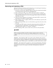
Unlock the battery release lever 1 and holding the battery release lever in the unlocked position 2 , remove the battery pack in the parts list for your computer. 1010 Battery pack DANGER Removing and replacing a FRU Use only the battery specified in the direction shown by arrow 3. 2 1 3 Lenovo 3000 N200 45 Any other battery could ignite or explode.
Unlock the battery release lever 1 and holding the battery release lever in the unlocked position 2 , remove the battery pack in the parts list for your computer. 1010 Battery pack DANGER Removing and replacing a FRU Use only the battery specified in the direction shown by arrow 3. 2 1 3 Lenovo 3000 N200 45 Any other battery could ignite or explode.

Hardware Maintenance Manual
Page 52
... cause damage and permanent loss of all the information on it . v Never remove the drive while the system is operating or is in order: v "1010 Battery pack" on page 45 v "1020 Hard disk drive slot cover" Attention v Do not drop the hard disk drive or apply any physical shock to physical... shock. Removing and replacing a FRU 1020 Hard disk drive slot cover For access, remove this FRU: v "1010 Battery pack" on page 45 Note: Loosen the screws 1 , but do not remove them. 2 1 1030 Hard disk drive For access, remove these FRUs in suspend mode...
... cause damage and permanent loss of all the information on it . v Never remove the drive while the system is operating or is in order: v "1010 Battery pack" on page 45 v "1020 Hard disk drive slot cover" Attention v Do not drop the hard disk drive or apply any physical shock to physical... shock. Removing and replacing a FRU 1020 Hard disk drive slot cover For access, remove this FRU: v "1010 Battery pack" on page 45 Note: Loosen the screws 1 , but do not remove them. 2 1 1030 Hard disk drive For access, remove these FRUs in suspend mode...

Hardware Maintenance Manual
Page 53
Removing and replacing a FRU 1040 DIMM slot cover For access, remove this FRU: v "1010 Battery pack" on page 45 Note: Loosen the screws 1 , but do not remove them. 1 2 Lenovo 3000 N200 47
Removing and replacing a FRU 1040 DIMM slot cover For access, remove this FRU: v "1010 Battery pack" on page 45 Note: Loosen the screws 1 , but do not remove them. 1 2 Lenovo 3000 N200 47

Hardware Maintenance Manual
Page 54
Removing and replacing a FRU 1050 DIMM For access, remove these FRUs in the slot and does not move easily. 48 MT 0687 Press the DIMM firmly, and pivot it until it is firmly fixed in order: v "1010 Battery pack" on page 45 v "1040 DIMM slot cover" on page 47 2 1 1 When installing: Insert the notched end of the DIMM into the place. Make sure that it snaps into the socket.
Removing and replacing a FRU 1050 DIMM For access, remove these FRUs in the slot and does not move easily. 48 MT 0687 Press the DIMM firmly, and pivot it until it is firmly fixed in order: v "1010 Battery pack" on page 45 v "1040 DIMM slot cover" on page 47 2 1 1 When installing: Insert the notched end of the DIMM into the place. Make sure that it snaps into the socket.
Hardware Maintenance Manual
Page 55
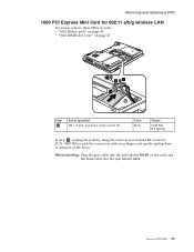
... the jacks by using the removal tool antenna RF connector (P/N: 08K7159) or pick the connectors with your fingers and gently unplug them in order: v "1010 Battery pack" on page 45 v "1040 DIMM slot cover" on the card, and the black cable into the jack labeled AUX...
... the jacks by using the removal tool antenna RF connector (P/N: 08K7159) or pick the connectors with your fingers and gently unplug them in order: v "1010 Battery pack" on page 45 v "1040 DIMM slot cover" on the card, and the black cable into the jack labeled AUX...


