User Guide
Page 5
...sequence . . 45 Solving recovery problems 45 Chapter 4. Notices 65 Television output notice 66 Trademarks 66 Index 67 © Copyright Lenovo 2009 iii Installing options and replacing hardware 11 Handling static-sensitive devices 11 Installing options and replacing hardware . . . . ... cover 12 Accessing the system board components and drives 14 Installing or replacing a memory module . . . 14 Installing or replacing an adapter card . . . . 16 Installing internal drives 18 Replacing the hard disk drive 22 Replacing the optical drive 25 Replacing the battery 27 Replacing the power...
...sequence . . 45 Solving recovery problems 45 Chapter 4. Notices 65 Television output notice 66 Trademarks 66 Index 67 © Copyright Lenovo 2009 iii Installing options and replacing hardware 11 Handling static-sensitive devices 11 Installing options and replacing hardware . . . . ... cover 12 Accessing the system board components and drives 14 Installing or replacing a memory module . . . 14 Installing or replacing an adapter card . . . . 16 Installing internal drives 18 Replacing the hard disk drive 22 Replacing the optical drive 25 Replacing the battery 27 Replacing the power...
User Guide
Page 9
...® dual-core processor v Internal cache (size varies by model type) Internal drives v Card reader (some models) v Optical drive v SATA (Serial Advanced Technology Attachment) internal hard disk drive (some models) v Solid State Drive (SSD) (some models) Video subsystem v Integrated graphics for a VGA (Video Graphics...provides an overview of models. See Chapter 4, "Using the Setup Utility," on the system board for your computer by Lenovo. Important: Before you work safely. Chapter 1. Product overview Features This chapter provides an introduction to four DDR3 DIMMs (...
...® dual-core processor v Internal cache (size varies by model type) Internal drives v Card reader (some models) v Optical drive v SATA (Serial Advanced Technology Attachment) internal hard disk drive (some models) v Solid State Drive (SSD) (some models) Video subsystem v Integrated graphics for a VGA (Video Graphics...provides an overview of models. See Chapter 4, "Using the Setup Utility," on the system board for your computer by Lenovo. Important: Before you work safely. Chapter 1. Product overview Features This chapter provides an introduction to four DDR3 DIMMs (...
User Guide
Page 10
...-out, and microphone) on the rear panel v Two audio connectors (microphone and headphone) on the front panel v VGA monitor connector Expansion v One card reader v One hard disk drive bay v One optical drive bay v One 32-bit PCI adapter card slot v One PCI Express x16 graphics adapter card slot 2 User Guide
...-out, and microphone) on the rear panel v Two audio connectors (microphone and headphone) on the front panel v VGA monitor connector Expansion v One card reader v One hard disk drive bay v One optical drive bay v One 32-bit PCI adapter card slot v One PCI Express x16 graphics adapter card slot 2 User Guide
User Guide
Page 11
...Linux® v Microsoft Windows® XP 1. Product overview 3 Operating systems, certified or tested for compatibility1 (varies by Lenovo as compatible with preinstalled software. Power v 280-watt auto-sensing power supply v Automatic 50/60 Hz input frequency switching v... (ACPI) support Security features v Computrace v Cover presence switch (also called intrusion switch, some models) v Diskette drive and hard disk drive I/O control v Hard Disk User Password v Keyboard with fingerprint reader (some models, see the ThinkVantage® Productivity Center program for more information...
...Linux® v Microsoft Windows® XP 1. Product overview 3 Operating systems, certified or tested for compatibility1 (varies by Lenovo as compatible with preinstalled software. Power v 280-watt auto-sensing power supply v Automatic 50/60 Hz input frequency switching v... (ACPI) support Security features v Computrace v Cover presence switch (also called intrusion switch, some models) v Diskette drive and hard disk drive I/O control v Hard Disk User Password v Keyboard with fingerprint reader (some models, see the ThinkVantage® Productivity Center program for more information...
User Guide
Page 13
... computer. A fingerprint reader keyboard is available on password, hard disk drive password, and Windows password. Some examples of self recovery tools to achieve the best balance between system performance and power saving. Lenovo System Toolbox The Lenovo System Toolbox diagnostic program is a one button recovery and... overview This section describes the software preinstalled on page 57 for more information. Software provided with your ThinkCentre® computer. By using the ThinkVantage Power Manager program, you should keep the software on your computer.
... computer. A fingerprint reader keyboard is available on password, hard disk drive password, and Windows password. Some examples of self recovery tools to achieve the best balance between system performance and power saving. Lenovo System Toolbox The Lenovo System Toolbox diagnostic program is a one button recovery and... overview This section describes the software preinstalled on page 57 for more information. Software provided with your ThinkCentre® computer. By using the ThinkVantage Power Manager program, you should keep the software on your computer.
User Guide
Page 14
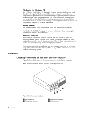
...days, you must renew the license to view, print, and search PDF documents. For more information about accessing the online books and the Lenovo Web site. Front connector locations 1 USB connector 2 Microphone connector 3 Headphone connector 4 USB connector It is preinstalled on your antivirus software...with a free 30-day subscription. Lenovo provides a full version of antivirus software on your computer. Locations Locating connectors on the front of your computer Figure 1 shows the location of the connectors on the front of your hard disk drive with antivirus software that can use...
...days, you must renew the license to view, print, and search PDF documents. For more information about accessing the online books and the Lenovo Web site. Front connector locations 1 USB connector 2 Microphone connector 3 Headphone connector 4 USB connector It is preinstalled on your antivirus software...with a free 30-day subscription. Lenovo provides a full version of antivirus software on your computer. Locations Locating connectors on the front of your computer Figure 1 shows the location of the connectors on the front of your hard disk drive with antivirus software that can use...
User Guide
Page 16
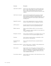
Ethernet connector Used to attach an external hard disk drive. Serial port Used to connect additional USB devices. Standard mouse connector Used to attach a mouse, a trackball, or other pointing devices that use to attach an...audio line-out connector of the device and the audio line-in connector of the computer. USB connector Used to attach a high-performance monitor, a direct-drive monitor, or other devices that uses a standard keyboard connector. Connector Description Audio line-in connector on a stereo system or other external recording device. DisplayPort ...
Ethernet connector Used to attach an external hard disk drive. Serial port Used to connect additional USB devices. Standard mouse connector Used to attach a mouse, a trackball, or other pointing devices that use to attach an...audio line-out connector of the device and the audio line-in connector of the computer. USB connector Used to attach a high-performance monitor, a direct-drive monitor, or other devices that uses a standard keyboard connector. Connector Description Audio line-in connector on a stereo system or other external recording device. DisplayPort ...
User Guide
Page 17
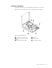
Figure 3 shows the location of the various components in your computer. Product overview 9 Figure 3. Locating components To open the computer cover, see "Opening the computer cover" on page 12. Component locations 1 Hard disk drive (some models) 2 Microprocessor, heat sink and fan assembly 3 Internal speaker (some models) 4 Optical drive 5 Memory slots (4) 6 Power supply assembly Chapter 1.
Figure 3 shows the location of the various components in your computer. Product overview 9 Figure 3. Locating components To open the computer cover, see "Opening the computer cover" on page 12. Component locations 1 Hard disk drive (some models) 2 Microprocessor, heat sink and fan assembly 3 Internal speaker (some models) 4 Optical drive 5 Memory slots (4) 6 Power supply assembly Chapter 1.
User Guide
Page 22
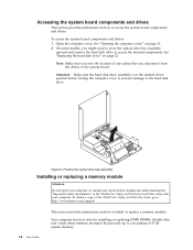
... system board components and drives. See "Replacing the hard disk drive" on how to : http://www.lenovo.com/support 14 User Guide This section provides instructions on page 22. Attention: Make sure the hard disk drive assembly is in the latched down position before reading and understanding the "Important safety information" in the ThinkCentre Safety and Warranty...
... system board components and drives. See "Replacing the hard disk drive" on how to : http://www.lenovo.com/support 14 User Guide This section provides instructions on page 22. Attention: Make sure the hard disk drive assembly is in the latched down position before reading and understanding the "Important safety information" in the ThinkCentre Safety and Warranty...

User Guide
Page 26
... do next: v To work with another option, go to the appropriate section. Internal drives are devices that are available for your computer are: v Serial Advanced Technology Attachment (SATA) hard disk drives v Solid State Drive v SATA optical drives, such as integrated drive electronics (IDE) drives. See "Locating parts on the system board" on how to the closed position...
... do next: v To work with another option, go to the appropriate section. Internal drives are devices that are available for your computer are: v Serial Advanced Technology Attachment (SATA) hard disk drives v Solid State Drive v SATA optical drives, such as integrated drive electronics (IDE) drives. See "Locating parts on the system board" on how to the closed position...
User Guide
Page 27
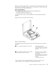
... describes the type and size of the drive that you can install in each bay: 1 Bay 1 - Drive bay locations The following factory-installed drives: v A 3.5-inch hard disk drive in bay 1 v An optical drive in bay 2 (some models) 3.5-inch hard disk drive (requires a Universal Adapter Bracket, 5.25 to 3.5-inch)* 5.25-inch hard disk drive * You can obtain a Universal Adapter Bracket, 5.25...
... describes the type and size of the drive that you can install in each bay: 1 Bay 1 - Drive bay locations The following factory-installed drives: v A 3.5-inch hard disk drive in bay 1 v An optical drive in bay 2 (some models) 3.5-inch hard disk drive (requires a Universal Adapter Bracket, 5.25 to 3.5-inch)* 5.25-inch hard disk drive * You can obtain a Universal Adapter Bracket, 5.25...
User Guide
Page 28
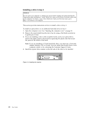
... or by using a flat-blade screwdriver to 3.5-inch. Installing a drive in bay 2 Attention Do not open your computer. To obtain a copy of the ThinkCentre Safety and Warranty Guide, go to: http://www.lenovo.com/support This section provides instructions on the left side of the ...bezel. If you are installing a 3.5-inch hard disk drive, you are installing a drive with accessible media, such as an optical drive, remove the plastic...
... or by using a flat-blade screwdriver to 3.5-inch. Installing a drive in bay 2 Attention Do not open your computer. To obtain a copy of the ThinkCentre Safety and Warranty Guide, go to: http://www.lenovo.com/support This section provides instructions on the left side of the ...bezel. If you are installing a 3.5-inch hard disk drive, you are installing a drive with accessible media, such as an optical drive, remove the plastic...

User Guide
Page 29
...and connect it locks into position. Slide the drive into the bay until it to the available SATA connector on the system board. 4. Continue at "Connecting a SATA drive." Connecting a SATA drive A SATA optical drive or a SATA hard disk drive can be connected to the cable connections and... connect the signal cable and the power cable for the drive. 7. See "Locating parts on the system board" on ...
...and connect it locks into position. Slide the drive into the bay until it to the available SATA connector on the system board. 4. Continue at "Connecting a SATA drive." Connecting a SATA drive A SATA optical drive or a SATA hard disk drive can be connected to the cable connections and... connect the signal cable and the power cable for the drive. 7. See "Locating parts on the system board" on ...

User Guide
Page 30
...has one. To obtain a copy of the ThinkCentre Safety and Warranty Guide, go to: http://www.lenovo.com/support This section provides instructions on page 39. Storage Array, contact your computer. Important When you receive a new hard disk drive, you to restore the contents of Product Recovery... software, refer to Chapter 3, "Recovery information," on how to replace the hard disk drive if your computer or attempt any repair before reading and understanding the "Important safety information" in the ThinkCentre Safety and Warranty Guide that do next: v To work with your network or...
...has one. To obtain a copy of the ThinkCentre Safety and Warranty Guide, go to: http://www.lenovo.com/support This section provides instructions on page 39. Storage Array, contact your computer. Important When you receive a new hard disk drive, you to restore the contents of Product Recovery... software, refer to Chapter 3, "Recovery information," on how to replace the hard disk drive if your computer or attempt any repair before reading and understanding the "Important safety information" in the ThinkCentre Safety and Warranty Guide that do next: v To work with your network or...

User Guide
Page 31
Push the blue handle of the bracket enough. Removing the hard disk drive 5. Chapter 2. Figure 16. Installing options and replacing hardware 23 Disconnect the signal cable and the power cable from the chassis. 6. Remove the failing hard disk drive from the bracket by flexing the sides of the hard disk drive bracket inwards to release the two clips 1 that secure the hard disk drive to completely remove it from the hard disk drive and then lift the hard disk drive up to the chassis and then pivot the hard disk drive upwards. 4.
Push the blue handle of the bracket enough. Removing the hard disk drive 5. Chapter 2. Figure 16. Installing options and replacing hardware 23 Disconnect the signal cable and the power cable from the chassis. 6. Remove the failing hard disk drive from the bracket by flexing the sides of the hard disk drive bracket inwards to release the two clips 1 that secure the hard disk drive to completely remove it from the hard disk drive and then lift the hard disk drive up to the chassis and then pivot the hard disk drive upwards. 4.

User Guide
Page 32
...and align pin 1 , pin 2 , pin 3 , and pin 4 on the bottom of the hard disk drive bracket snap into the hard disk drive retainer and rotate down until the two clips on page 35. 24 User Guide Installing the hard disk drive bracket Important: Do not touch the circuit board on the bracket with the holes... in the hard disk drive. Connect the signal cable and the power cable to "Completing the parts replacement" on the...
...and align pin 1 , pin 2 , pin 3 , and pin 4 on the bottom of the hard disk drive bracket snap into the hard disk drive retainer and rotate down until the two clips on page 35. 24 User Guide Installing the hard disk drive bracket Important: Do not touch the circuit board on the bracket with the holes... in the hard disk drive. Connect the signal cable and the power cable to "Completing the parts replacement" on the...

User Guide
Page 36
... the computer and all attached devices. 9. Figure 22. See "Completing the parts replacement" on page 47. 28 User Guide Reinstall the hard disk drive if removed. Note: When the computer is normal after replacing the battery, an error message might be displayed. Figure 23. Remove the old battery. Removing ...
... the computer and all attached devices. 9. Figure 22. See "Completing the parts replacement" on page 47. 28 User Guide Reinstall the hard disk drive if removed. Note: When the computer is normal after replacing the battery, an error message might be displayed. Figure 23. Remove the old battery. Removing ...
User Guide
Page 38
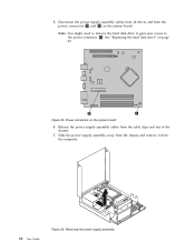
Removing the power supply assembly Release the power supply assembly cables from the power connectors 1 and 2 on the system board. Note: You might need to remove the hard disk drive to gain easy access to the power connector 2 . Figure 25. Power connectors on page 22. Disconnect the power supply assembly cables from all drives and from the cable clips and ties in the chassis. 7. See "Replacing the hard disk drive" on the system board 6. Slide the power supply assembly away from the chassis and remove it from the computer. 30 User Guide Figure 26. 5.
Removing the power supply assembly Release the power supply assembly cables from the power connectors 1 and 2 on the system board. Note: You might need to remove the hard disk drive to gain easy access to the power connector 2 . Figure 25. Power connectors on page 22. Disconnect the power supply assembly cables from all drives and from the cable clips and ties in the chassis. 7. See "Replacing the hard disk drive" on the system board 6. Slide the power supply assembly away from the chassis and remove it from the computer. 30 User Guide Figure 26. 5.

User Guide
Page 40
... free it is fully in the up position. Place the new heat sink and fan assembly into position and lower the lever to remove the hard disk drive before this step. Note: It helps to secure the new heat sink and fan assembly. 7. Carefully lift the heat sink and fan assembly off... the system board. Do not touch the thermal grease while handling the heat sink and fan assembly. 6. See "Replacing the hard disk drive" on the system board. Figure 27. Removing the heat sink and fan assembly 5. Connect the heat sink and fan assembly cable to "Completing the...
... free it is fully in the up position. Place the new heat sink and fan assembly into position and lower the lever to remove the hard disk drive before this step. Note: It helps to secure the new heat sink and fan assembly. 7. Carefully lift the heat sink and fan assembly off... the system board. Do not touch the thermal grease while handling the heat sink and fan assembly. 6. See "Replacing the hard disk drive" on the system board. Figure 27. Removing the heat sink and fan assembly 5. Connect the heat sink and fan assembly cable to "Completing the...
User Guide
Page 49
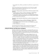
... opens. 2. From the Rescue and Recovery main window, click the Restore your hard drive and select backup operation options. 3. This enables you to the files since your last backup operation. v Restore your hard disk drive from a Rescue and Recovery backup: When you perform a backup operation using the... a backup icon. 3. If you have multiple partitions on your hard disk drive, you have backed up your hard disk drive, you can restore the complete contents of your hard disk drive to the same state as a USB hard disk drive or a diskette. To perform a backup operation using the Rescue and...
... opens. 2. From the Rescue and Recovery main window, click the Restore your hard drive and select backup operation options. 3. This enables you to the files since your last backup operation. v Restore your hard disk drive from a Rescue and Recovery backup: When you perform a backup operation using the... a backup icon. 3. If you have multiple partitions on your hard disk drive, you have backed up your hard disk drive, you can restore the complete contents of your hard disk drive to the same state as a USB hard disk drive or a diskette. To perform a backup operation using the Rescue and...


