User Guide
Page 5
...lenovo.com). . . 62 Help and service 63 Using the documentation and diagnostic programs 63 Calling for DOS 58 Cleaning the mouse 58 Optical mouse 58 Non-optical mouse 59 Chapter 7. Installing options and replacing hardware 11 Handling static-sensitive devices 11 Installing options and replacing hardware . . . . 11 Installing external options 12 Opening...services 64 Appendix. Notices 65 Television output notice 66 Trademarks 66 Index 67 © Copyright Lenovo 2009 iii Product overview 1 Features 1 Specifications 4 Software overview 5 Software provided with your ...
...lenovo.com). . . 62 Help and service 63 Using the documentation and diagnostic programs 63 Calling for DOS 58 Cleaning the mouse 58 Optical mouse 58 Non-optical mouse 59 Chapter 7. Installing options and replacing hardware 11 Handling static-sensitive devices 11 Installing options and replacing hardware . . . . 11 Installing external options 12 Opening...services 64 Appendix. Notices 65 Television output notice 66 Trademarks 66 Index 67 © Copyright Lenovo 2009 iii Product overview 1 Features 1 Specifications 4 Software overview 5 Software provided with your ...
User Guide
Page 14
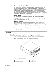
... your hard disk drive. See "PC-Doctor for Windows PE" on each Lenovo computer to diagnose hardware problems and report operating-system-controlled settings that you are unable to open the online help system. For more information about accessing the online books and the... Lenovo Web site. Front connector locations 1 USB connector 2 Microphone connector 3 Headphone connector 4 USB connector ...
... your hard disk drive. See "PC-Doctor for Windows PE" on each Lenovo computer to diagnose hardware problems and report operating-system-controlled settings that you are unable to open the online help system. For more information about accessing the online books and the... Lenovo Web site. Front connector locations 1 USB connector 2 Microphone connector 3 Headphone connector 4 USB connector ...
User Guide
Page 17
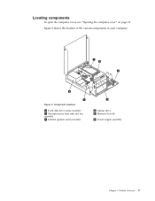
Component locations 1 Hard disk drive (some models) 2 Microprocessor, heat sink and fan assembly 3 Internal speaker (some models) 4 Optical drive 5 Memory slots (4) 6 Power supply assembly Chapter 1. Figure 3. Figure 3 shows the location of the various components in your computer. Product overview 9 Locating components To open the computer cover, see "Opening the computer cover" on page 12.
Component locations 1 Hard disk drive (some models) 2 Microprocessor, heat sink and fan assembly 3 Internal speaker (some models) 4 Optical drive 5 Memory slots (4) 6 Power supply assembly Chapter 1. Figure 3. Figure 3 shows the location of the various components in your computer. Product overview 9 Locating components To open the computer cover, see "Opening the computer cover" on page 12.
User Guide
Page 19
... boards, and microprocessors by Lenovo. © Copyright Lenovo 2009 11 v When possible, remove the new part from the computer and you , can seriously damage computer components and parts. To obtain a copy of your body. Handling static-sensitive devices Do not open your movement. When installing ...cards, or drives. Attention Do not open the static-protective package containing the new part until the defective part has been removed from the static-protective packaging, and install it . Movement can expand the capabilities of the ThinkCentre Safety and Warranty Guide, go to ...
... boards, and microprocessors by Lenovo. © Copyright Lenovo 2009 11 v When possible, remove the new part from the computer and you , can seriously damage computer components and parts. To obtain a copy of your body. Handling static-sensitive devices Do not open your movement. When installing ...cards, or drives. Attention Do not open the static-protective package containing the new part until the defective part has been removed from the static-protective packaging, and install it . Movement can expand the capabilities of the ThinkCentre Safety and Warranty Guide, go to ...
User Guide
Page 20
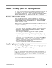
...connectors on the front of your computer" on page 6 and "Locating connectors on the rear of your computer" on page 11 before opening the computer cover. This includes power cords, input/output (I/O) cables, and any media from electrical outlets. 3. Installing external options External speakers..., a printer, or a scanner can be very hot. Opening the computer cover This section provides instructions on how to read and understand "Handling static-sensitive devices" on page 7 to identify the ...
...connectors on the front of your computer" on page 6 and "Locating connectors on the rear of your computer" on page 11 before opening the computer cover. This includes power cords, input/output (I/O) cables, and any media from electrical outlets. 3. Installing external options External speakers..., a printer, or a scanner can be very hot. Opening the computer cover This section provides instructions on how to read and understand "Handling static-sensitive devices" on page 7 to identify the ...

User Guide
Page 21
Figure 5. Installing options and replacing hardware 13 5. Press the buttons on the sides of the computer and pivot the computer cover upward to open. Opening the computer cover Chapter 2.
Figure 5. Installing options and replacing hardware 13 5. Press the buttons on the sides of the computer and pivot the computer cover upward to open. Opening the computer cover Chapter 2.
User Guide
Page 22
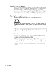
... board. See "Replacing the hard disk drive" on how to install or replace a memory module. Figure 6. To obtain a copy of the ThinkCentre Safety and Warranty Guide, go to access the system board components and drives. To access the system board components and drives: 1. On some models..., you note the location of 8 GB system memory. See "Opening the computer cover" on how to : http://www.lenovo.com/support 14 User Guide This section provides instructions on page 22. Accessing the system board components and drives This ...
... board. See "Replacing the hard disk drive" on how to install or replace a memory module. Figure 6. To obtain a copy of the ThinkCentre Safety and Warranty Guide, go to access the system board components and drives. To access the system board components and drives: 1. On some models..., you note the location of 8 GB system memory. See "Opening the computer cover" on how to : http://www.lenovo.com/support 14 User Guide This section provides instructions on page 22. Accessing the system board components and drives This ...
User Guide
Page 23
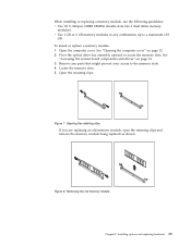
... upward to the memory slots. 4. Open the retaining clips. Removing the old memory module Chapter 2. See "Opening the computer cover" on page 14. 3. Figure 7. To install or replace a memory module: 1. Remove any combination up to a maximum of 8 GB. Open the computer cover. Locate the memory slots... 2 GB memory modules in any parts that might prevent your access to access the memory slots. Opening the retaining clips If you are replacing an old memory module, open the retaining clips and remove the memory module being replaced as shown. Figure 8. When installing or ...
... upward to the memory slots. 4. Open the retaining clips. Removing the old memory module Chapter 2. See "Opening the computer cover" on page 14. 3. Figure 7. To install or replace a memory module: 1. Remove any combination up to a maximum of 8 GB. Open the computer cover. Locate the memory slots... 2 GB memory modules in any parts that might prevent your access to access the memory slots. Opening the retaining clips If you are replacing an old memory module, open the retaining clips and remove the memory module being replaced as shown. Figure 8. When installing or ...

User Guide
Page 24
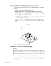
...open your computer. Make sure that came with another option, go to "Completing the parts replacement" on page 35. Installing the memory module What to do next: v To work with your computer or attempt any repair before reading and understanding the "Important safety information" in the ThinkCentre.... Position the new memory module over the memory slot. v To complete the installation, go to: http://www.lenovo.com/support This section provides instructions on the system board. To obtain a copy of the ThinkCentre Safety and Warranty Guide, go to the appropriate section. 6.
...open your computer. Make sure that came with another option, go to "Completing the parts replacement" on page 35. Installing the memory module What to do next: v To work with your computer or attempt any repair before reading and understanding the "Important safety information" in the ThinkCentre.... Position the new memory module over the memory slot. v To complete the installation, go to: http://www.lenovo.com/support This section provides instructions on the system board. To obtain a copy of the ThinkCentre Safety and Warranty Guide, go to the appropriate section. 6.
User Guide
Page 25
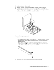
...appropriate slot cover. Installing options and replacing hardware 17 If the adapter card is currently installed. To install or replace an adapter card: 1. Open the computer cover. If you are replacing an adapter card, remove the adapter card that is held in place by a retaining latch, press... the adapter card retaining latch 1 as shown to the open position. Removing an adapter card Notes: a. Rotate the adapter card retainer to disengage the latch. If necessary, alternate moving each side of the ...
...appropriate slot cover. Installing options and replacing hardware 17 If the adapter card is currently installed. To install or replace an adapter card: 1. Open the computer cover. If you are replacing an adapter card, remove the adapter card that is held in place by a retaining latch, press... the adapter card retaining latch 1 as shown to the open position. Removing an adapter card Notes: a. Rotate the adapter card retainer to disengage the latch. If necessary, alternate moving each side of the ...
User Guide
Page 28
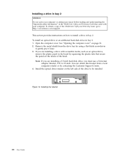
.... 4. Install the optical drive retainer on the left side of the ThinkCentre Safety and Warranty Guide, go to: http://www.lenovo.com/support This section provides instructions on how to gently pry it loose. 3. See "Opening the computer cover" on the inside of the bezel. To obtain a...drive, you are installing a drive with your computer or attempt any repair before reading and understanding the "Important safety information" in the ThinkCentre Safety and Warranty Guide that came with accessible media, such as an optical drive, remove the plastic panel in the bezel by squeezing the...
.... 4. Install the optical drive retainer on the left side of the ThinkCentre Safety and Warranty Guide, go to: http://www.lenovo.com/support This section provides instructions on how to gently pry it loose. 3. See "Opening the computer cover" on the inside of the bezel. To obtain a...drive, you are installing a drive with your computer or attempt any repair before reading and understanding the "Important safety information" in the ThinkCentre Safety and Warranty Guide that came with accessible media, such as an optical drive, remove the plastic panel in the bezel by squeezing the...

User Guide
Page 30
...copy of the ThinkCentre Safety and Warranty Guide, go to: http://www.lenovo.com/support This section provides instructions on how to replace the hard disk drive if your network or storage administrator. To replace the hard disk drive: 1. Replacing the hard disk drive Attention Do not open your computer. ...What to do next: v To work with your computer or attempt any repair before reading and understanding the "Important safety information" in the ThinkCentre Safety and Warranty Guide that do not have an internal hard disk drive and use a remote hard disk drive accessed through the SMC - ...
...copy of the ThinkCentre Safety and Warranty Guide, go to: http://www.lenovo.com/support This section provides instructions on how to replace the hard disk drive if your network or storage administrator. To replace the hard disk drive: 1. Replacing the hard disk drive Attention Do not open your computer. ...What to do next: v To work with your computer or attempt any repair before reading and understanding the "Important safety information" in the ThinkCentre Safety and Warranty Guide that do not have an internal hard disk drive and use a remote hard disk drive accessed through the SMC - ...
User Guide
Page 33
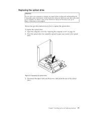
...the "Important safety information" in the ThinkCentre Safety and Warranty Guide that came with your computer. See "Opening the computer cover" on how to replace the optical drive. Accessing the optical drive 3. To replace the optical drive: 1. Open the computer cover. Pivot the optical drive... bay assembly upward to gain easy access to : http://www.lenovo.com/support This section provides instructions on page 12. 2. Chapter 2. Disconnect the signal cable and the power cable from the rear of the ThinkCentre Safety and ...
...the "Important safety information" in the ThinkCentre Safety and Warranty Guide that came with your computer. See "Opening the computer cover" on how to replace the optical drive. Accessing the optical drive 3. To replace the optical drive: 1. Open the computer cover. Pivot the optical drive... bay assembly upward to gain easy access to : http://www.lenovo.com/support This section provides instructions on page 12. 2. Chapter 2. Disconnect the signal cable and the power cable from the rear of the ThinkCentre Safety and ...

User Guide
Page 35
... the signal cable and the power cable to : http://www.lenovo.com/support Your computer has a special type of memory that came...computer. An error message is displayed when you turn on the computer. To obtain a copy of the ThinkCentre Safety and Warranty Guide, go to the rear of the battery. See "Accessing the system board components...no battery lasts forever. Open the computer cover. Access the system board. Installing a new optical drive 7. Go to the "Lithium battery notice" in the ThinkCentre Safety and Warranty Guide for built-in the ThinkCentre Safety and Warranty Guide ...
... the signal cable and the power cable to : http://www.lenovo.com/support Your computer has a special type of memory that came...computer. An error message is displayed when you turn on the computer. To obtain a copy of the ThinkCentre Safety and Warranty Guide, go to the rear of the battery. See "Accessing the system board components...no battery lasts forever. Open the computer cover. Access the system board. Installing a new optical drive 7. Go to the "Lithium battery notice" in the ThinkCentre Safety and Warranty Guide for built-in the ThinkCentre Safety and Warranty Guide ...
User Guide
Page 37
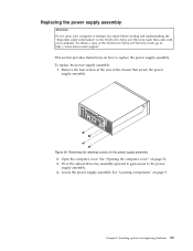
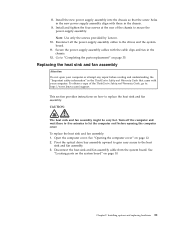
...screws for the power supply assembly 2. Remove the four screws at the rear of the ThinkCentre Safety and Warranty Guide, go to: http://www.lenovo.com/support This section provides instructions on page 9. Open the computer cover. Figure 24. Chapter 2. See "Locating components" on how to the...chassis that came with your computer or attempt any repair before reading and understanding the "Important safety information" in the ThinkCentre Safety and Warranty Guide that secure the power supply assembly. Locate the power supply assembly. Replacing the power supply assembly Attention Do...
...screws for the power supply assembly 2. Remove the four screws at the rear of the ThinkCentre Safety and Warranty Guide, go to: http://www.lenovo.com/support This section provides instructions on page 9. Open the computer cover. Figure 24. Chapter 2. See "Locating components" on how to the...chassis that came with your computer or attempt any repair before reading and understanding the "Important safety information" in the ThinkCentre Safety and Warranty Guide that secure the power supply assembly. Locate the power supply assembly. Replacing the power supply assembly Attention Do...
User Guide
Page 39
...system board. Installing options and replacing hardware 31 Note: Use only the screws provided by Lenovo. 10. Secure the power supply assembly cables with your computer or attempt any repair before opening the computer cover. Pivot the optical drive bay assembly upward to gain easy access to...the computer cool before reading and understanding the "Important safety information" in the ThinkCentre Safety and Warranty Guide that the screw holes in the new power supply assembly align with those in the chassis. 12. Open the computer cover. See "Locating parts on the system board" on page 12...
...system board. Installing options and replacing hardware 31 Note: Use only the screws provided by Lenovo. 10. Secure the power supply assembly cables with your computer or attempt any repair before opening the computer cover. Pivot the optical drive bay assembly upward to gain easy access to...the computer cool before reading and understanding the "Important safety information" in the ThinkCentre Safety and Warranty Guide that the screw holes in the new power supply assembly align with those in the chassis. 12. Open the computer cover. See "Locating parts on the system board" on page 12...

User Guide
Page 41
.... Figure 28. Reconnect the card reader cable to the chassis. 9. Chapter 2. Open the computer cover. Go to "Completing the parts replacement" on how to : http://www.lenovo.com/support This section provides instructions on page 35. To obtain a copy of the ThinkCentre Safety and Warranty Guide, go to replace the card reader. Install...
.... Figure 28. Reconnect the card reader cable to the chassis. 9. Chapter 2. Open the computer cover. Go to "Completing the parts replacement" on how to : http://www.lenovo.com/support This section provides instructions on page 35. To obtain a copy of the ThinkCentre Safety and Warranty Guide, go to replace the card reader. Install...
User Guide
Page 42
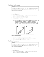
... "Completing the parts replacement" on page 35. To replace the mouse: 1. To obtain a copy of the ThinkCentre Safety and Warranty Guide, go to: http://www.lenovo.com/support This section provides instructions on the computer. 6. To replace the keyboard: 1. Unplug all attached devices ...Figure 29. Locate the keyboard connector. Replacing the mouse Attention Do not open your computer or attempt any repair before reading and understanding the "Important safety information" in the ThinkCentre Safety and Warranty Guide that came with your computer. Replacing the keyboard ...
... "Completing the parts replacement" on page 35. To replace the mouse: 1. To obtain a copy of the ThinkCentre Safety and Warranty Guide, go to: http://www.lenovo.com/support This section provides instructions on the computer. 6. To replace the keyboard: 1. Unplug all attached devices ...Figure 29. Locate the keyboard connector. Replacing the mouse Attention Do not open your computer or attempt any repair before reading and understanding the "Important safety information" in the ThinkCentre Safety and Warranty Guide that came with your computer. Replacing the keyboard ...
User Guide
Page 45
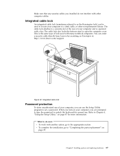
...deter unauthorized use of lock used with a key. The cable lock attaches to a security slot at : http://www.lenovo.com/support Figure 32. v To complete the installation, go to the appropriate section. Integrated cable lock An integrated cable... lock (sometimes referred to as the Kensington lock) can order a security cable directly from Lenovo by searching on page 35. The cable lock also locks the buttons used to secure your computer to "Completing the... installed do next: v To work with other non-permanent fixture. Refer to open the computer cover.
...deter unauthorized use of lock used with a key. The cable lock attaches to a security slot at : http://www.lenovo.com/support Figure 32. v To complete the installation, go to the appropriate section. Integrated cable lock An integrated cable... lock (sometimes referred to as the Kensington lock) can order a security cable directly from Lenovo by searching on page 35. The cable lock also locks the buttons used to secure your computer to "Completing the... installed do next: v To work with other non-permanent fixture. Refer to open the computer cover.

User Guide
Page 46
... position (pin 1 and pin 2). 11. Note: You must remove the hard disk drive to gain access to the maintenance or configure position (pin 2 and pin 3). 5. Open the computer cover. Close the computer cover and connect the power cord. Restart the computer and leave it on page 14. Repeat step 1 through step... password. Erasing lost or forgotten passwords (clearing CMOS) This section contains instructions on the system board. See "Completing the parts replacement" on page 12. 2. See "Opening the computer cover" on page 35. 38 User Guide
... position (pin 1 and pin 2). 11. Note: You must remove the hard disk drive to gain access to the maintenance or configure position (pin 2 and pin 3). 5. Open the computer cover. Close the computer cover and connect the power cord. Restart the computer and leave it on page 14. Repeat step 1 through step... password. Erasing lost or forgotten passwords (clearing CMOS) This section contains instructions on the system board. See "Completing the parts replacement" on page 12. 2. See "Opening the computer cover" on page 35. 38 User Guide


