
User Manual
Page 5
... environment xi Electrical current safety information xi Lithium battery notice xii Modem safety information xii Laser compliance statement xiii Power supply statement xiii Data safety xiv Cleaning and maintenance xiv Additional safety information xiv Introduction xv Chapter 1. Installing options... 9 Installing other operating systems 9 Updating your computer 18 Obtaining device drivers 19 Opening the cover 20 Locating components 21 © Lenovo 2005, 2007. Arranging your operating system 50 Recovering from a POST/BIOS update failure . . . 50 Chapter 7. Contents Important ...
... environment xi Electrical current safety information xi Lithium battery notice xii Modem safety information xii Laser compliance statement xiii Power supply statement xiii Data safety xiv Cleaning and maintenance xiv Additional safety information xiv Introduction xv Chapter 1. Installing options... 9 Installing other operating systems 9 Updating your computer 18 Obtaining device drivers 19 Opening the cover 20 Locating components 21 © Lenovo 2005, 2007. Arranging your operating system 50 Recovering from a POST/BIOS update failure . . . 50 Chapter 7. Contents Important ...

User Manual
Page 8
... substances on page 61 for further guidance. Lenovo provides documentation with an ac power cord, always make sure that the power is turned off and that the product is not manufactured for your computer after the power cord has been disconnected, the following warnings ... Before you remove the covers from a product equipped with instructions when it from any power source. v Power cords, plugs, power adapters, extension cords, surge protectors, or power supplies that are required for or by Lenovo, stop using that product until you get a suitable replacement. v Damage to install ...
... substances on page 61 for further guidance. Lenovo provides documentation with an ac power cord, always make sure that the power is turned off and that the product is not manufactured for your computer after the power cord has been disconnected, the following warnings ... Before you remove the covers from a product equipped with instructions when it from any power source. v Power cords, plugs, power adapters, extension cords, surge protectors, or power supplies that are required for or by Lenovo, stop using that product until you get a suitable replacement. v Damage to install ...

User Manual
Page 10
...the computer to an electrical outlet until you set to operate only at the ac input or anywhere on floors that all power cord connectors are equipped with liquid cleansers. If you relocate your computer has a voltage-selection switch, ensure that you have...Protect power cord and power adapters from liquids. Always connect power cords and signal cables in any power cords where the electrical contacts on the computer. Do not use any way. The power cords shall be used accordingly. Power cords and power adapters Use only the power cords and power adapters supplied by ...
...the computer to an electrical outlet until you set to operate only at the ac input or anywhere on floors that all power cord connectors are equipped with liquid cleansers. If you relocate your computer has a voltage-selection switch, ensure that you have...Protect power cord and power adapters from liquids. Always connect power cords and signal cables in any power cords where the electrical contacts on the computer. Do not use any way. The power cords shall be used accordingly. Power cords and power adapters Use only the power cords and power adapters supplied by ...
User Manual
Page 11
...any external device cables other home or commercial appliances that the power outlet you are using is on; Batteries All personal computers manufactured by Lenovo contain a non-rechargeable coin cell battery to provide power to disconnect external devices. Consult an electrician for more information...to replace the outlet with a three-pronged plug. Extension cords and related devices Ensure that extension cords, surge protectors, uninterruptible power supplies, and power strips that will stress the cords. Do not bend or modify the plug. This is damaged, contact the manufacturer to ...
...any external device cables other home or commercial appliances that the power outlet you are using is on; Batteries All personal computers manufactured by Lenovo contain a non-rechargeable coin cell battery to provide power to disconnect external devices. Consult an electrician for more information...to replace the outlet with a three-pronged plug. Extension cords and related devices Ensure that extension cords, surge protectors, uninterruptible power supplies, and power strips that will stress the cords. Do not bend or modify the plug. This is damaged, contact the manufacturer to ...

User Manual
Page 12
...areas. If you notice external dust accumulation, you should inspect your computer within 2 feet of the computer including heat sink inlet fins, power supply vents, and fans. For your body for long periods of time. x User Guide For some heat during normal operation. Heat and...contacts. These features might inadvertently become blocked by Lenovo for use with approved parts. then remove any discharge from your desktop computer: v Keep the cover closed whenever the computer is charging. provide system power when in . Batteries supplied by placing the product on and when batteries ...
...areas. If you notice external dust accumulation, you should inspect your computer within 2 feet of the computer including heat sink inlet fins, power supply vents, and fans. For your body for long periods of time. x User Guide For some heat during normal operation. Heat and...contacts. These features might inadvertently become blocked by Lenovo for use with approved parts. then remove any discharge from your desktop computer: v Keep the cover closed whenever the computer is charging. provide system power when in . Batteries supplied by placing the product on and when batteries ...
User Manual
Page 15
...-1 for Class 1 laser products. These drives are also sold separately as options. Note the following handling instructions. Danger Laser radiation when open. Power supply statement Never remove the cover on a power supply or any component that has the following label attached. If you suspect a problem with a CD or DVD drive. to conform to the...
...-1 for Class 1 laser products. These drives are also sold separately as options. Note the following handling instructions. Danger Laser radiation when open. Power supply statement Never remove the cover on a power supply or any component that has the following label attached. If you suspect a problem with a CD or DVD drive. to conform to the...
User Manual
Page 21
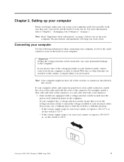
...electrical outlet. Look for travelers to the country or region where you are equipped with a voltage-selection switch located near the power-cord connection point on page v before you set the voltage-selection switch to 115 V. Important Setting the voltage-selection switch .... Connecting your computer Use the following information when connecting your local electric company or refer to 230 V. 115 © Lenovo 2005, 2007. v If the voltage supply range in this section. Some models are located. If necessary, use a ballpoint pen to slide the switch to the computer...
...electrical outlet. Look for travelers to the country or region where you are equipped with a voltage-selection switch located near the power-cord connection point on page v before you set the voltage-selection switch to 115 V. Important Setting the voltage-selection switch .... Connecting your computer Use the following information when connecting your local electric company or refer to 230 V. 115 © Lenovo 2005, 2007. v If the voltage supply range in this section. Some models are located. If necessary, use a ballpoint pen to slide the switch to the computer...
User Manual
Page 31
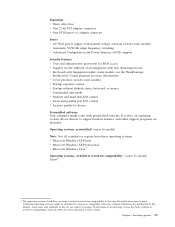
...Productivity Center program for compatibility1 (varies by Lenovo as compatible with preinstalled software. Expansion v Three drive bays v One 32-bit PCI adapter connector v One PCI Express x1 adapter connector Power v 225 Watt power supply with manual voltage selection switch (some models)... v Automatic 50/60 Hz input frequency switching v Advanced Configuration and Power Interface (ACPI) support Security features v User and administrator passwords...
...Productivity Center program for compatibility1 (varies by Lenovo as compatible with preinstalled software. Expansion v Three drive bays v One 32-bit PCI adapter connector v One PCI Express x1 adapter connector Power v 225 Watt power supply with manual voltage selection switch (some models)... v Automatic 50/60 Hz input frequency switching v Advanced Configuration and Power Interface (ACPI) support Security features v User and administrator passwords...
User Manual
Page 33
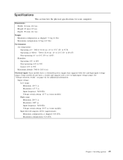
Some models do not have a switchable power supply that supports both low and high input voltage ranges. See "Voltage-selection switch" on page viii for your computer. Specifications This section lists the physical ...
Some models do not have a switchable power supply that supports both low and high input voltage ranges. See "Voltage-selection switch" on page viii for your computer. Specifications This section lists the physical ...

User Manual
Page 36
Locating connectors on the rear of your computer The following illustration shows the locations of connectors on the rear of your computer. 1 Power cord connector 9 2 Cable lock latch 10 3 PCI Express x1 adapter connector 11 4 PCI adapter connector 12 5 USB connectors (4) 13 6 Ethernet...connector 16 Parallel connector Serial connector Mouse connector Keyboard Audio line out connector Audio line in connector Voltage-selection switch (some models) Power supply diagnostic LEDs Note: Some connectors on the rear of your computer are color-coded to help you determine where to connect the ...
Locating connectors on the rear of your computer The following illustration shows the locations of connectors on the rear of your computer. 1 Power cord connector 9 2 Cable lock latch 10 3 PCI Express x1 adapter connector 11 4 PCI adapter connector 12 5 USB connectors (4) 13 6 Ethernet...connector 16 Parallel connector Serial connector Mouse connector Keyboard Audio line out connector Audio line in connector Voltage-selection switch (some models) Power supply diagnostic LEDs Note: Some connectors on the rear of your computer are color-coded to help you determine where to connect the ...
User Manual
Page 39
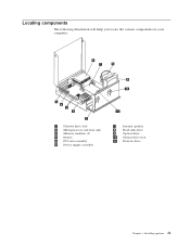
Installing options 21 Locating components The following illustration will help you locate the various components in your computer. 1 Diskette drive lock 2 Microprocessor and heat sink 3 Memory modules (2) 4 Battery 5 PCI riser assembly 6 Power supply assembly 7 Internal speaker 8 Hard disk drive 9 Optical drive 10 Optical drive lock 11 Diskette drive Chapter 3.
Installing options 21 Locating components The following illustration will help you locate the various components in your computer. 1 Diskette drive lock 2 Microprocessor and heat sink 3 Memory modules (2) 4 Battery 5 PCI riser assembly 6 Power supply assembly 7 Internal speaker 8 Hard disk drive 9 Optical drive 10 Optical drive lock 11 Diskette drive Chapter 3.

User Manual
Page 41
... connector 1 10 Internal speaker connector 2 Memory connector 2 11 Diskette drive connector 3 SATA IDE connectors (2) 12 Front panel connector 4 BIOS WP 13 Power supply connector 5 Cover presence switch (Tamper 14 12v power connector SW) connector 6 PCI riser connector 15 Microprocessor 7 Battery 16 Fan connector 2 8 Clear CMOS/Recovery jumper 17 Fan connector 1 9 Temperature sensor connector...
... connector 1 10 Internal speaker connector 2 Memory connector 2 11 Diskette drive connector 3 SATA IDE connectors (2) 12 Front panel connector 4 BIOS WP 13 Power supply connector 5 Cover presence switch (Tamper 14 12v power connector SW) connector 6 PCI riser connector 15 Microprocessor 7 Battery 16 Fan connector 2 8 Clear CMOS/Recovery jumper 17 Fan connector 1 9 Temperature sensor connector...

User Manual
Page 53
... bay assembly and make sure that the cables are both in the Setup Utility program. Chapter 3. Close the computer cover and connect the power cord. Repeat steps 1 through 3 on for approximately 5 seconds. Move the Clear CMOS/Recovery jumper back to install any removed parts, ...connect cables to confirm the updated information in the locked position. Important Correctly route all components have been reassembled correctly and that all power supply cables to avoid interference with options, you might need to the standard position (pins 1 and 2). 11. Installing options 35 See ...
... bay assembly and make sure that the cables are both in the Setup Utility program. Chapter 3. Close the computer cover and connect the power cord. Repeat steps 1 through 3 on for approximately 5 seconds. Move the Clear CMOS/Recovery jumper back to install any removed parts, ...connect cables to confirm the updated information in the locked position. Important Correctly route all components have been reassembled correctly and that all power supply cables to avoid interference with options, you might need to the standard position (pins 1 and 2). 11. Installing options 35 See ...


