
User Manual
Page 5
... the cover 20 Locating components 21 © Lenovo 2005, 2007. ix Plugs and outlets ix External devices ix Batteries ix Heat and product ventilation x Operating environment xi Electrical current safety information xi Lithium battery notice xii Modem safety information xii Laser compliance statement xiii Power supply statement xiii Data safety xiv Cleaning and...
... the cover 20 Locating components 21 © Lenovo 2005, 2007. ix Plugs and outlets ix External devices ix Batteries ix Heat and product ventilation x Operating environment xi Electrical current safety information xi Lithium battery notice xii Modem safety information xii Laser compliance statement xiii Power supply statement xiii Data safety xiv Cleaning and...

User Manual
Page 8
...options or replace CRUs. Note: If you can be upgraded or replaced by the customer. Lenovo provides documentation with an ac power cord, always make sure that the power is approved to water. If you follow all instructions when installing or replacing parts. v Signs...Always observe the following warnings are cracked, broken, or damaged. Before you get a suitable replacement. v Power cords, plugs, power adapters, extension cords, surge protectors, or power supplies that voltage levels inside a product are no moving parts in any questions or concerns, contact the Customer Support...
...options or replace CRUs. Note: If you can be upgraded or replaced by the customer. Lenovo provides documentation with an ac power cord, always make sure that the power is approved to water. If you follow all instructions when installing or replacing parts. v Signs...Always observe the following warnings are cracked, broken, or damaged. Before you get a suitable replacement. v Power cords, plugs, power adapters, extension cords, surge protectors, or power supplies that voltage levels inside a product are no moving parts in any questions or concerns, contact the Customer Support...

User Manual
Page 10
...was originally purchased. Liquids can cause the cord to have verified that can cause a short circuit, particularly if the power cord or power adapter has been stressed by the product manufacturer. Liquids also can cause permanent damage to another country, be H05VV-F, ... the following: v If your computer to the computer. The power cords shall be used accordingly. Power cords and power adapters Use only the power cords and power adapters supplied by misuse. Never wrap a power cord around a power adapter or other countries, the suitable types shall be safety approved...
...was originally purchased. Liquids can cause the cord to have verified that can cause a short circuit, particularly if the power cord or power adapter has been stressed by the product manufacturer. Liquids also can cause permanent damage to another country, be H05VV-F, ... the following: v If your computer to the computer. The power cords shall be used accordingly. Power cords and power adapters Use only the power cords and power adapters supplied by misuse. Never wrap a power cord around a power adapter or other countries, the suitable types shall be safety approved...
User Manual
Page 11
...unstable voltage might damage your computer, data, or attached devices. Batteries All personal computers manufactured by Lenovo contain a non-rechargeable coin cell battery to provide power to obtain a replacement. This plug fits only into the outlet, contact an electrician for the... or region where you are located. Extension cords and related devices Ensure that extension cords, surge protectors, uninterruptible power supplies, and power strips that enables this safety feature by a qualified electrician. Carefully connect and disconnect the equipment from the electrical ...
...unstable voltage might damage your computer, data, or attached devices. Batteries All personal computers manufactured by Lenovo contain a non-rechargeable coin cell battery to provide power to obtain a replacement. This plug fits only into the outlet, contact an electrician for the... or region where you are located. Extension cords and related devices Ensure that extension cords, surge protectors, uninterruptible power supplies, and power strips that enables this safety feature by a qualified electrician. Carefully connect and disconnect the equipment from the electrical ...

User Manual
Page 12
... can degrade when they are left unused for dust accumulation at least once every three months. These features might inadvertently become blocked by Lenovo for dust accumulation. If you notice external dust accumulation, you notice any dust from vents and perforations in portable mode. v Regularly inspect...use with your lap or any battery. Never attempt to overheat, which could shorten the life of the computer including heat sink inlet fins, power supply vents, and fans. Never block, cover, or disable these basic precautions: v Do not leave the base of your safety and to ...
... can degrade when they are left unused for dust accumulation at least once every three months. These features might inadvertently become blocked by Lenovo for dust accumulation. If you notice external dust accumulation, you notice any dust from vents and perforations in portable mode. v Regularly inspect...use with your lap or any battery. Never attempt to overheat, which could shorten the life of the computer including heat sink inlet fins, power supply vents, and fans. Never block, cover, or disable these basic precautions: v Do not leave the base of your safety and to ...
User Manual
Page 15
v Do not use the telephone to the beam. These drives are also sold separately as options. Danger Laser radiation when open. Power supply statement Never remove the cover on a power supply or any component that has the following label attached. Laser compliance statement Some personal computer models are present inside the CD or DVD drive...
v Do not use the telephone to the beam. These drives are also sold separately as options. Danger Laser radiation when open. Power supply statement Never remove the cover on a power supply or any component that has the following label attached. Laser compliance statement Some personal computer models are present inside the CD or DVD drive...
User Manual
Page 21
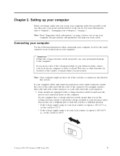
...are located. If you are equipped with a voltage-selection switch located near the power-cord connection point on page v before you set up your computer Before you begin.... Portions © IBM Corp. 2005. 3 For more information, refer to 230 V. 115 © Lenovo 2005, 2007. If your computer has a voltage-selection switch, ensure that suits your needs and the kind of... to match the voltage available at your electrical outlet, contact your computer. v If the voltage supply range is in your computer. If necessary, use a ballpoint pen to slide the switch to the...
...are located. If you are equipped with a voltage-selection switch located near the power-cord connection point on page v before you set up your computer Before you begin.... Portions © IBM Corp. 2005. 3 For more information, refer to 230 V. 115 © Lenovo 2005, 2007. If your computer has a voltage-selection switch, ensure that suits your needs and the kind of... to match the voltage available at your electrical outlet, contact your computer. v If the voltage supply range is in your computer. If necessary, use a ballpoint pen to slide the switch to the...
User Manual
Page 31
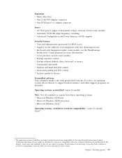
...Home v Microsoft Windows XP Professional v Microsoft Windows Vista™ Operating systems, certified or tested for compatibility1 (varies by Lenovo as compatible with preinstalled software. The operating systems listed here are being certified or tested for compatibility at the time ...32-bit PCI adapter connector v One PCI Express x1 adapter connector Power v 225 Watt power supply with manual voltage selection switch (some models) v Automatic 50/60 Hz input frequency switching v Advanced Configuration and Power Interface (ACPI) support Security features v User and administrator passwords ...
...Home v Microsoft Windows XP Professional v Microsoft Windows Vista™ Operating systems, certified or tested for compatibility1 (varies by Lenovo as compatible with preinstalled software. The operating systems listed here are being certified or tested for compatibility at the time ...32-bit PCI adapter connector v One PCI Express x1 adapter connector Power v 225 Watt power supply with manual voltage selection switch (some models) v Automatic 50/60 Hz input frequency switching v Advanced Configuration and Power Interface (ACPI) support Security features v User and administrator passwords ...
User Manual
Page 33
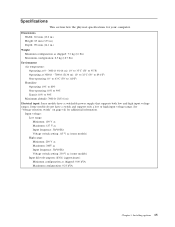
...: 358 mm (14.1 in.) Weight Minimum configuration as shipped: 0.09 kVA Maximum configuration: 0.23 kVA Chapter 3. Installing options 15 Some models do not have a switchable power supply that supports both low and high input voltage ranges. Input voltage: Low range: Minimum: 100 V ac Maximum: 127 V ac Input frequency: 50/60 Hz Voltage...
...: 358 mm (14.1 in.) Weight Minimum configuration as shipped: 0.09 kVA Maximum configuration: 0.23 kVA Chapter 3. Installing options 15 Some models do not have a switchable power supply that supports both low and high input voltage ranges. Input voltage: Low range: Minimum: 100 V ac Maximum: 127 V ac Input frequency: 50/60 Hz Voltage...

User Manual
Page 36
Locating connectors on the rear of your computer The following illustration shows the locations of connectors on the rear of your computer. 1 Power cord connector 9 2 Cable lock latch 10 3 PCI Express x1 adapter connector 11 4 PCI adapter connector 12 5 USB connectors (4) 13 6 Ethernet...connector 16 Parallel connector Serial connector Mouse connector Keyboard Audio line out connector Audio line in connector Voltage-selection switch (some models) Power supply diagnostic LEDs Note: Some connectors on the rear of your computer are color-coded to help you determine where to connect the ...
Locating connectors on the rear of your computer The following illustration shows the locations of connectors on the rear of your computer. 1 Power cord connector 9 2 Cable lock latch 10 3 PCI Express x1 adapter connector 11 4 PCI adapter connector 12 5 USB connectors (4) 13 6 Ethernet...connector 16 Parallel connector Serial connector Mouse connector Keyboard Audio line out connector Audio line in connector Voltage-selection switch (some models) Power supply diagnostic LEDs Note: Some connectors on the rear of your computer are color-coded to help you determine where to connect the ...
User Manual
Page 39
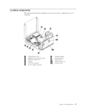
Installing options 21 Locating components The following illustration will help you locate the various components in your computer. 1 Diskette drive lock 2 Microprocessor and heat sink 3 Memory modules (2) 4 Battery 5 PCI riser assembly 6 Power supply assembly 7 Internal speaker 8 Hard disk drive 9 Optical drive 10 Optical drive lock 11 Diskette drive Chapter 3.
Installing options 21 Locating components The following illustration will help you locate the various components in your computer. 1 Diskette drive lock 2 Microprocessor and heat sink 3 Memory modules (2) 4 Battery 5 PCI riser assembly 6 Power supply assembly 7 Internal speaker 8 Hard disk drive 9 Optical drive 10 Optical drive lock 11 Diskette drive Chapter 3.

User Manual
Page 41
... connector 1 10 Internal speaker connector 2 Memory connector 2 11 Diskette drive connector 3 SATA IDE connectors (2) 12 Front panel connector 4 BIOS WP 13 Power supply connector 5 Cover presence switch (Tamper 14 12v power connector SW) connector 6 PCI riser connector 15 Microprocessor 7 Battery 16 Fan connector 2 8 Clear CMOS/Recovery jumper 17 Fan connector 1 9 Temperature sensor connector...
... connector 1 10 Internal speaker connector 2 Memory connector 2 11 Diskette drive connector 3 SATA IDE connectors (2) 12 Front panel connector 4 BIOS WP 13 Power supply connector 5 Cover presence switch (Tamper 14 12v power connector SW) connector 6 PCI riser connector 15 Microprocessor 7 Battery 16 Fan connector 2 8 Clear CMOS/Recovery jumper 17 Fan connector 1 9 Temperature sensor connector...

User Manual
Page 53
...9. Reinstall the PCI riser assembly if removed. 12. Installing options 35 Important Correctly route all components have been reassembled correctly and that all power supply cables to the standard position (pins 1 and 2). 11. Keep cables clear of the hinges and sides of the computer chassis. 3. ... the computer cover. Restart the computer, leave it on page 34. 10. The computer will turn off the computer by holding the power switch for approximately 10 seconds. Repeat steps 1 through 3 on for approximately 5 seconds. Closing the cover and connecting the cables After ...
...9. Reinstall the PCI riser assembly if removed. 12. Installing options 35 Important Correctly route all components have been reassembled correctly and that all power supply cables to the standard position (pins 1 and 2). 11. Keep cables clear of the hinges and sides of the computer chassis. 3. ... the computer cover. Restart the computer, leave it on page 34. 10. The computer will turn off the computer by holding the power switch for approximately 10 seconds. Repeat steps 1 through 3 on for approximately 5 seconds. Closing the cover and connecting the cables After ...


