IdeaPad Z570 Keyboard Bezel - Lenovo
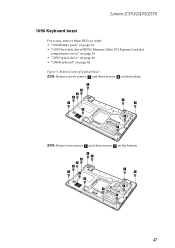
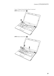
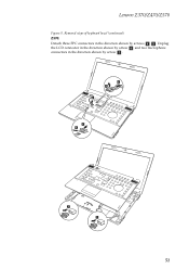
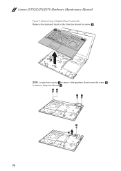
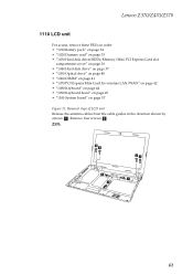
IdeaPad Z570 Keyboard Bezel
View Results Below
Free Lenovo IdeaPad Z570 manuals!
Problems with Lenovo IdeaPad Z570?
Ask a Question
Free Lenovo IdeaPad Z570 manuals!
Problems with Lenovo IdeaPad Z570?
Ask a Question
Related Manual Pages

Similar Questions

Lenovo Ideapad Z370 Keyboard How To Disassemble
(Posted by mfitcbbrumf 9 years ago)


Keyboard
How do I activate the backlighting on the keyboard? or does this model not have one?
How do I activate the backlighting on the keyboard? or does this model not have one?
(Posted by tayhinton55 10 years ago)

Keyboard Removal
I am replacing the keyboard on a nearly new z750 1024. The 3 screws are out. How do I pop out the ke...
I am replacing the keyboard on a nearly new z750 1024. The 3 screws are out. How do I pop out the ke...
(Posted by bfinstad 11 years ago)

Keyboard Issues
Hello. I've recently acquired a lenovo G780. My operating system has been installed without fault, a...
Hello. I've recently acquired a lenovo G780. My operating system has been installed without fault, a...
(Posted by silviuvanaero 11 years ago)