Lenovo H520s Hardware Maintenance Manual
Page 5
...39 Replacing the Wi-Fi card 41 Replacing the front USB/card reader/audio module 42 Replacing the motherboard 43 FRU lists 45 Chapter 9. Using the Setup Utility. . . 13 Starting the Lenovo BIOS Setup Utility program . 13 Viewing and changing settings 13 Using passwords 13 Enabling or disabling a... device 15 Selecting a startup device 16 Exiting the Lenovo BIOS Setup Utility program . . 17 Chapter 6. Symptom-to-FRU Index . . 19 Hard disk drive boot error 19 Power Supply Problems 19 ...
...39 Replacing the Wi-Fi card 41 Replacing the front USB/card reader/audio module 42 Replacing the motherboard 43 FRU lists 45 Chapter 9. Using the Setup Utility. . . 13 Starting the Lenovo BIOS Setup Utility program . 13 Viewing and changing settings 13 Using passwords 13 Enabling or disabling a... device 15 Selecting a startup device 16 Exiting the Lenovo BIOS Setup Utility program . . 17 Chapter 6. Symptom-to-FRU Index . . 19 Hard disk drive boot error 19 Power Supply Problems 19 ...

Lenovo H520s Hardware Maintenance Manual
Page 31
...a variety of devices that are factory-installed or that you can install later. The following illustration shows the location of connectors and components on the motherboard The motherboard (sometimes called the planar or system board) is the main circuit board in your computer. SATA connectors (3) 9. eSATA connector 10. Front USB ... 5. Power fan header 13 12 11 10 11. Mini PCI-E slot 15. Front audio connector 19. Identifying parts on the front of the motherboard. 1 2 3 4 5 6 7 8 9 18 17 16 15 14 1. 12V power connector 2. PCI express X 16 adapter slot 20.
...a variety of devices that are factory-installed or that you can install later. The following illustration shows the location of connectors and components on the motherboard The motherboard (sometimes called the planar or system board) is the main circuit board in your computer. SATA connectors (3) 9. eSATA connector 10. Front USB ... 5. Power fan header 13 12 11 10 11. Mini PCI-E slot 15. Front audio connector 19. Identifying parts on the front of the motherboard. 1 2 3 4 5 6 7 8 9 18 17 16 15 14 1. 12V power connector 2. PCI express X 16 adapter slot 20.
Lenovo H520s Hardware Maintenance Manual
Page 40
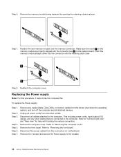
... close. Remove any other cables that secure the Power supply to "Left and right view" and "Rear view" for help with the connector key 2 on motherboard. Step 6. This includes power cords, input/output (I/O) cables, and any media (disks, CDs, DVDs, or memory cards) from electrical outlets. Refer to the computer. Step...
... close. Remove any other cables that secure the Power supply to "Left and right view" and "Rear view" for help with the connector key 2 on motherboard. Step 6. This includes power cords, input/output (I/O) cables, and any media (disks, CDs, DVDs, or memory cards) from electrical outlets. Refer to the computer. Step...
Lenovo H520s Hardware Maintenance Manual
Page 41
Line up the holes on the new power supply with mounting holes on the motherboard. Reattach the front bezel, computer cover. Disconnect all cables attached to the chassis with locating the various connectors. Refer to "Left and right view" and "...
Line up the holes on the new power supply with mounting holes on the motherboard. Reattach the front bezel, computer cover. Disconnect all cables attached to the chassis with locating the various connectors. Refer to "Left and right view" and "...
Lenovo H520s Hardware Maintenance Manual
Page 42
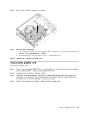
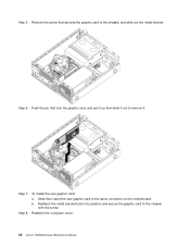
Step 6. b. Reattach the computer cover. 36 Lenovo H520sHardware Maintenance Manual Push the pin that secures the graphic card to remove it. Step 7. Remove the screw that lock the graphic card, and pull it up then slide it out to the chassis, and slide out the metal bracket. Step 8. To install the new graphic card: a. Slide then insert the new graphic card to the chassis with the screw. Step 5. Reattach the metal bracket back into position and secure the graphic card to the same connector on the motherboard.
Step 6. b. Reattach the computer cover. 36 Lenovo H520sHardware Maintenance Manual Push the pin that secures the graphic card to remove it. Step 7. Remove the screw that lock the graphic card, and pull it up then slide it out to the chassis, and slide out the metal bracket. Step 8. To install the new graphic card: a. Slide then insert the new graphic card to the chassis with the screw. Step 5. Reattach the metal bracket back into position and secure the graphic card to the same connector on the motherboard.

Lenovo H520s Hardware Maintenance Manual
Page 43
Step 3. Step 4. Step 5. Disconnect all cables attached to the connector on the motherboard. Refer to "Removing the computer cover". Disconnect the fan power cable from electrical outlets. To install the new system fan: a. Connect the system fan ..., or memory cards) from the drives, shut down the operating system, and turn off the computer and all power cords from the connector on the motherboard. Refer to "Removing the front bezel". b. Replacing the system fan To replace the system fan: Step 1. Step 2. Unplug all attached devices. Step 9. Remove the ...
Step 3. Step 4. Step 5. Disconnect all cables attached to the connector on the motherboard. Refer to "Removing the computer cover". Disconnect the fan power cable from electrical outlets. To install the new system fan: a. Connect the system fan ..., or memory cards) from the drives, shut down the operating system, and turn off the computer and all power cords from the connector on the motherboard. Refer to "Removing the front bezel". b. Replacing the system fan To replace the system fan: Step 1. Step 2. Unplug all attached devices. Step 9. Remove the ...

Lenovo H520s Hardware Maintenance Manual
Page 45
... "Left and right view" and "Rear view" for help with locating the various connectors. Step 5. Refer to remove it. Refer to the motherboard. Install the new heat-sink: a. Reattach the computer cover. Step 2. Disconnect all power cords from the drives, shut down the operating ...system, and turn off the computer and all cables attached to the connector on the motherboard and secure it helps to the heat-sink. Refer to the computer. Step 6. Refer to "Replacing the microprocessor fan". To replace the...
... "Left and right view" and "Rear view" for help with locating the various connectors. Step 5. Refer to remove it. Refer to the motherboard. Install the new heat-sink: a. Reattach the computer cover. Step 2. Disconnect all power cords from the drives, shut down the operating ...system, and turn off the computer and all cables attached to the connector on the motherboard and secure it helps to the heat-sink. Refer to the computer. Step 6. Refer to "Replacing the microprocessor fan". To replace the...

Lenovo H520s Hardware Maintenance Manual
Page 47
... grease should be 0.03ml (3 tick marks on the microprocessor are aligned with your fingers, position the microprocessor so that protects the gold contacts on the motherboard. To secure the microprocessor in the microprocessor socket. Holding the sides of the microprocessor with the small handle. Lower the microprocessor straight down into the...
... grease should be 0.03ml (3 tick marks on the microprocessor are aligned with your fingers, position the microprocessor so that protects the gold contacts on the motherboard. To secure the microprocessor in the microprocessor socket. Holding the sides of the microprocessor with the small handle. Lower the microprocessor straight down into the...
Lenovo H520s Hardware Maintenance Manual
Page 48
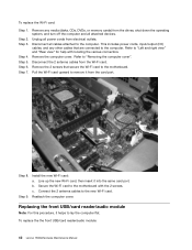
...to the computer. Refer to "Left and right view" and "Rear view" for help with the 2 screws. Remove the 2 screws that are connected to the motherboard. Step 9. This includes power cords, input/output (I/O) cables, and any media (disks, CDs, DVDs, or memory cards) from the drives, shut down the... cables from the card port. Install the new Wi-Fi card: a. c. Step 4. To replace the the front USB/card reader/audio module: 42 Lenovo H520sHardware Maintenance Manual Disconnect all cables attached to the new Wi-Fi card. Remove the computer cover. Line up the new Wi-Fi card, then...
...to the computer. Refer to "Left and right view" and "Rear view" for help with the 2 screws. Remove the 2 screws that are connected to the motherboard. Step 9. This includes power cords, input/output (I/O) cables, and any media (disks, CDs, DVDs, or memory cards) from the drives, shut down the... cables from the card port. Install the new Wi-Fi card: a. c. Step 4. To replace the the front USB/card reader/audio module: 42 Lenovo H520sHardware Maintenance Manual Disconnect all cables attached to the new Wi-Fi card. Remove the computer cover. Line up the new Wi-Fi card, then...
Lenovo H520s Hardware Maintenance Manual
Page 49
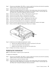
...drive. Step 7. Step 9. Step 10. c. Step 3. Refer to "Replacing the hard disk drive". b. Step 4. Refer to the motherboard. Remove the power supply. Connect the data cables to "Replacing the optical drive". Reattach the power supply, hard disk drive and optical ...Removing the computer cover". Remove the screw that are connected to the chassis. Step 6. Chapter 8. Unplug all attached devices. Replacing the motherboard Note: For this procedure, it with locating the various connectors. This includes power cords, input/output (I /O) cables, and any media...
...drive. Step 7. Step 9. Step 10. c. Step 3. Refer to "Replacing the hard disk drive". b. Step 4. Refer to the motherboard. Remove the power supply. Connect the data cables to "Replacing the optical drive". Reattach the power supply, hard disk drive and optical ...Removing the computer cover". Remove the screw that are connected to the chassis. Step 6. Chapter 8. Unplug all attached devices. Replacing the motherboard Note: For this procedure, it with locating the various connectors. This includes power cords, input/output (I /O) cables, and any media...
Lenovo H520s Hardware Maintenance Manual
Page 50
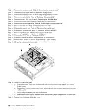
... hard disk drive". Remove the TV-Tuner card. Step 15. Step 16. Remove the 6 screws that secure the motherboard to "Replacing a memory module". Step 18. b. Reattach the front bezel, computer cover. 44 Lenovo H520sHardware Maintenance Manual Refer to the chassis. Refer to "Replacing the Wi-Fi card". Refer to "Replacing the power...
... hard disk drive". Remove the TV-Tuner card. Step 15. Step 16. Remove the 6 screws that secure the motherboard to "Replacing a memory module". Step 18. b. Reattach the front bezel, computer cover. 44 Lenovo H520sHardware Maintenance Manual Refer to the chassis. Refer to "Replacing the Wi-Fi card". Refer to "Replacing the power...
User Guide
Page 12
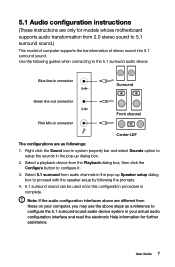
... procedure is complete. User Guide 7 Select a playback device from those on your actual audio configuration interface and read the electronic Help information for models whose motherboard supports audio transformation from 2.0 stereo sound to proceed with the speaker setup by following guides when connecting to configure it. 3. Note: If the audio configuration...
... procedure is complete. User Guide 7 Select a playback device from those on your actual audio configuration interface and read the electronic Help information for models whose motherboard supports audio transformation from 2.0 stereo sound to proceed with the speaker setup by following guides when connecting to configure it. 3. Note: If the audio configuration...

User Guide
Page 38
It provides basic computer functions and supports a variety of devices that are factory-installed or that you can install later. Lenovo H505s 12 3 4 5 6 13 12 11 10 9 8 7 Microprocessor and heat sink Memory slots (2) Thermal sensor header Battery Mini PCI-E slot Clear CMOS jumper Front audio connector ... connectors (2) Front USB connectors (2) PCI express X 1 adapter slot User Guide 33 Identifying parts on the system board The system board (sometimes called the planar or motherboard) is the main circuit board in your computer.
It provides basic computer functions and supports a variety of devices that are factory-installed or that you can install later. Lenovo H505s 12 3 4 5 6 13 12 11 10 9 8 7 Microprocessor and heat sink Memory slots (2) Thermal sensor header Battery Mini PCI-E slot Clear CMOS jumper Front audio connector ... connectors (2) Front USB connectors (2) PCI express X 1 adapter slot User Guide 33 Identifying parts on the system board The system board (sometimes called the planar or motherboard) is the main circuit board in your computer.


