Lenovo H5 Series User Guide
Page 39
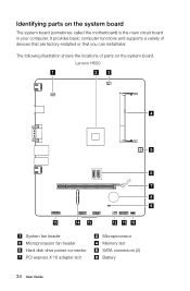
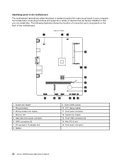
The following illustration shows the locations of devices that are factory-installed or that you can install later. Identifying parts on the system board. Lenovo H500 1 23 4 5 6 7 8 9 15 14 13 System fan header Microprocessor fan header Hard disk drive power connector PCI express X 16 adapter slot 12 11 10 Microprocessor Memory slot SATA connectors (2) Battery 34 User Guide It provides basic computer functions and supports a variety of parts on the system board The system board (sometimes called the motherboard) is the main circuit board in your computer.
The following illustration shows the locations of devices that are factory-installed or that you can install later. Identifying parts on the system board. Lenovo H500 1 23 4 5 6 7 8 9 15 14 13 System fan header Microprocessor fan header Hard disk drive power connector PCI express X 16 adapter slot 12 11 10 Microprocessor Memory slot SATA connectors (2) Battery 34 User Guide It provides basic computer functions and supports a variety of parts on the system board The system board (sometimes called the motherboard) is the main circuit board in your computer.
Lenovo H5 Series User Guide
Page 46
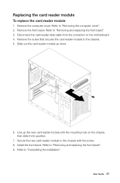
... To replace the card reader module 1. Remove the computer cover. Refer to "Completing the installation". Refer to the chassis with the mounting hole on the motherboard. 4. Line up the new card reader module with the screw. 8. Secure the new card reader module to "Removing and replacing the front bezel". 9. Refer to...
... To replace the card reader module 1. Remove the computer cover. Refer to "Completing the installation". Refer to the chassis with the mounting hole on the motherboard. 4. Line up the new card reader module with the screw. 8. Secure the new card reader module to "Removing and replacing the front bezel". 9. Refer to...
Lenovo H500 Hardware Maintenance Manual
Page 5
...37 Replacing the Power supply 40 Replacing the Wi-Fi card 40 Replacing the front card reader module . . . . . 41 Replacing the motherboard 42 Chapter 9. Safety information 3 General safety 3 Electrical safety 3 Safety inspection guide 5 Handling electrostatic discharge-sensitive devices 5 Grounding requirements 6 ...Safety notices 6 Chapter 3. General information . . . . 45 Additional Service Information 45 © Copyright Lenovo 2013 iii Symptom-to-FRU Index . . 19 Hard disk drive boot error 19 Power Supply Problems 19 POST error codes 20 ...
...37 Replacing the Power supply 40 Replacing the Wi-Fi card 40 Replacing the front card reader module . . . . . 41 Replacing the motherboard 42 Chapter 9. Safety information 3 General safety 3 Electrical safety 3 Safety inspection guide 5 Handling electrostatic discharge-sensitive devices 5 Grounding requirements 6 ...Safety notices 6 Chapter 3. General information . . . . 45 Additional Service Information 45 © Copyright Lenovo 2013 iii Symptom-to-FRU Index . . 19 Hard disk drive boot error 19 Power Supply Problems 19 POST error codes 20 ...
Lenovo H500 Hardware Maintenance Manual
Page 30
... PCI-E slot 15. System fan header 13. Lenovo H500 1 23 4 5 15 1. SATA connectors (2) 7. Battery 6 7 8 9 14 13 12 11 10 9. Memory slot 5. It provides basic computing functions and supports a variety of the motherboard. The following illustration shows the location of connectors and components on the motherboard The motherboard (sometimes called the planar or system board) is...
... PCI-E slot 15. System fan header 13. Lenovo H500 1 23 4 5 15 1. SATA connectors (2) 7. Battery 6 7 8 9 14 13 12 11 10 9. Memory slot 5. It provides basic computing functions and supports a variety of the motherboard. The following illustration shows the location of connectors and components on the motherboard The motherboard (sometimes called the planar or system board) is...
Lenovo H500 Hardware Maintenance Manual
Page 41
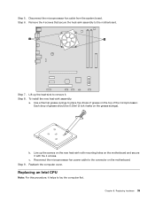
... secure it helps to place five drops of grease on the top of grease should be 0.03ml (3 tick marks on the motherboard. Reconnect the microprocessor fan power cable to remove it. Replacing an Intel CPU Note: For this procedure, it with the 4 screws. Step 6. Each drop of ...-sink assembly: a. Use a thermal grease syringe to lay the computer flat. Replacing hardware 35 Remove the 4 screws that secure the heat-sink assembly to the motherboard. Step 7. Line up the heat-sink to the connector on the grease syringe). c. Step 9. Chapter 8. Step 8.
... secure it helps to place five drops of grease on the top of grease should be 0.03ml (3 tick marks on the motherboard. Reconnect the microprocessor fan power cable to remove it. Replacing an Intel CPU Note: For this procedure, it with the 4 screws. Step 6. Each drop of ...-sink assembly: a. Use a thermal grease syringe to lay the computer flat. Replacing hardware 35 Remove the 4 screws that secure the heat-sink assembly to the motherboard. Step 7. Line up the heat-sink to the connector on the grease syringe). c. Step 9. Chapter 8. Step 8.
Lenovo H500 Hardware Maintenance Manual
Page 43
... should be 0.03ml (3 tick marks on the top of the microprocessor with your fingers, remove the protective cover 1 that protects the gold contacts on the motherboard. Replacing hardware 37 Step 12. Reattach the heat-sink assembly and the computer cover. Unplug all power cords from the drives, shut down into the...
... should be 0.03ml (3 tick marks on the top of the microprocessor with your fingers, remove the protective cover 1 that protects the gold contacts on the motherboard. Replacing hardware 37 Step 12. Reattach the heat-sink assembly and the computer cover. Unplug all power cords from the drives, shut down into the...
Lenovo H500 Hardware Maintenance Manual
Page 44
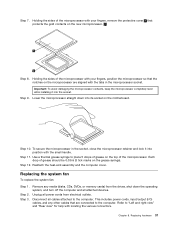
Disconnect the fan power cable from the connector on the motherboard. Pull the system fan assembly out of the chassis. 38 Lenovo H500Hardware Maintenance Manual Step 6. Step 5. Remove the computer cover. Refer to "Removing the computer cover". Step 4.
Disconnect the fan power cable from the connector on the motherboard. Pull the system fan assembly out of the chassis. 38 Lenovo H500Hardware Maintenance Manual Step 6. Step 5. Remove the computer cover. Refer to "Removing the computer cover". Step 4.
Lenovo H500 Hardware Maintenance Manual
Page 46
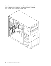
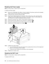
... procedure, it helps to lay the computer flat. Step 5. Disconnect all attached devices. Refer to the computer. Disconnect the power cables from the connectors on motherboard. 1 Remove the 4 screws that are connected to the computer. Line up the holes on the new power supply with mounting holes on the...
... procedure, it helps to lay the computer flat. Step 5. Disconnect all attached devices. Refer to the computer. Disconnect the power cables from the connectors on motherboard. 1 Remove the 4 screws that are connected to the computer. Line up the holes on the new power supply with mounting holes on the...
Lenovo H500 Hardware Maintenance Manual
Page 47
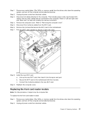
Step 4. This includes power cords, input/output (I/O) cables, and any other cables that secure the Wi-Fi card to the motherboard. Refer to the computer. Step 8. Secure the Wi-Fi card to the new Wi-Fi card. Remove any media (disks, CDs, DVDs, or... the operating system, and turn off the computer and all power cords from the card port. Step 2. Step 6. Connect the 2 antenna cables to the motherboard with locating the various connectors. Chapter 8. Step 2. Step 3. Step 5. Remove the computer cover. Reattach the computer cover. Pull the Wi-Fi card upward...
Step 4. This includes power cords, input/output (I/O) cables, and any other cables that secure the Wi-Fi card to the motherboard. Refer to the computer. Step 8. Secure the Wi-Fi card to the new Wi-Fi card. Remove any media (disks, CDs, DVDs, or... the operating system, and turn off the computer and all power cords from the card port. Step 2. Step 6. Connect the 2 antenna cables to the motherboard with locating the various connectors. Chapter 8. Step 2. Step 3. Step 5. Remove the computer cover. Reattach the computer cover. Pull the Wi-Fi card upward...
Lenovo H500 Hardware Maintenance Manual
Page 48
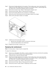
...) from the drives, shut down the operating system, and turn off the computer and all power cords from the connectors on motherboard. Refer to "Removing the computer cover". Step 3. Install the new front card reader module: a. Unplug all attached devices. ...Connect the data cables to "Removing the front bezel". Step 4. b. Replacing the motherboard Note: For this procedure, it with screw. Refer to the motherboard. Step 9. Refer to "Replacing a memory module". 42 Lenovo H500Hardware Maintenance Manual Step 10. Step 8. Refer to "Removing the front bezel". ...
...) from the drives, shut down the operating system, and turn off the computer and all power cords from the connectors on motherboard. Refer to "Removing the computer cover". Step 3. Install the new front card reader module: a. Unplug all attached devices. ...Connect the data cables to "Removing the front bezel". Step 4. b. Replacing the motherboard Note: For this procedure, it with screw. Refer to the motherboard. Step 9. Refer to "Replacing a memory module". 42 Lenovo H500Hardware Maintenance Manual Step 10. Step 8. Refer to "Removing the front bezel". ...
Lenovo H500 Hardware Maintenance Manual
Page 49
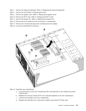
... the graphic card. Disconnect the all cables to "Replacing the system fan". Remove the 6 screws that secure the motherboard to "Replacing the graphic card". Install the new motherboard: a. Refer to the chassis. Remove the system fan. Step 13. Reattach the memory module, Wi-Fi card,... connectors on the chassis and secure it . Step 11. c. Chapter 8. Refer to the new motherboard. Step 12. Lift up the holes on the new motherboard with mounting holes on motherboard. Refer to "Replacing the Wi-Fi card". Remove the CPU. Reattach the hard disk drive, ...
... the graphic card. Disconnect the all cables to "Replacing the system fan". Remove the 6 screws that secure the motherboard to "Replacing the graphic card". Install the new motherboard: a. Refer to the chassis. Remove the system fan. Step 13. Reattach the memory module, Wi-Fi card,... connectors on the chassis and secure it . Step 11. c. Chapter 8. Refer to the new motherboard. Step 12. Lift up the holes on the new motherboard with mounting holes on motherboard. Refer to "Replacing the Wi-Fi card". Remove the CPU. Reattach the hard disk drive, ...


