User Guide
Page 3
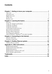
... to the Internet 31 Wired connection ...31 Wireless connection 32 Chapter 4. CRU instructions 35 Replacing the battery 35 Replacing the hard disk drive 37 Replacing memory ...44 Replacing the wireless LAN card 48 Removing the optical drive 50 Trademarks 52 Index...53 i
... to the Internet 31 Wired connection ...31 Wireless connection 32 Chapter 4. CRU instructions 35 Replacing the battery 35 Replacing the hard disk drive 37 Replacing memory ...44 Replacing the wireless LAN card 48 Removing the optical drive 50 Trademarks 52 Index...53 i
User Guide
Page 13
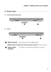
Chapter 1. b System status indicators For details, see "Using memory cards (not supplied)" on page 27. 9 Note: For details, see "System status indicators" on page 24. Getting to know your computer Front view „ G480/G485/G580/G585 „ G780 2 1 2 1 a Memory card slot Insert memory cards (not supplied) here.
Chapter 1. b System status indicators For details, see "Using memory cards (not supplied)" on page 27. 9 Note: For details, see "System status indicators" on page 24. Getting to know your computer Front view „ G480/G485/G580/G585 „ G780 2 1 2 1 a Memory card slot Insert memory cards (not supplied) here.
User Guide
Page 19
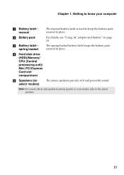
d Hard disk drive (HDD)/Memory/ CPU (Central processing unit)/ Mini PCI Express Card slot compartment e Speakers (on page 18. The spring-loaded battery latch keeps the battery pack secured in ...
d Hard disk drive (HDD)/Memory/ CPU (Central processing unit)/ Mini PCI Express Card slot compartment e Speakers (on page 18. The spring-loaded battery latch keeps the battery pack secured in ...
User Guide
Page 28
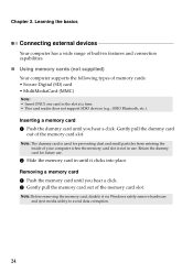
... is not in the slot at a time. • This card reader does not support SDIO devices (e.g., SDIO Bluetooth, etc.). Note: Before removing the memory card, disable it clicks into place. Note: The dummy card is used for future use . Retain the dummy card for preventing dust and small particles ...from entering the inside of the memory card slot. Learning the basics Connecting external devices Your computer has a wide range of built-in features and connection capabilities. „ Using...
... is not in the slot at a time. • This card reader does not support SDIO devices (e.g., SDIO Bluetooth, etc.). Note: Before removing the memory card, disable it clicks into place. Note: The dummy card is used for future use . Retain the dummy card for preventing dust and small particles ...from entering the inside of the memory card slot. Learning the basics Connecting external devices Your computer has a wide range of built-in features and connection capabilities. „ Using...
User Guide
Page 42
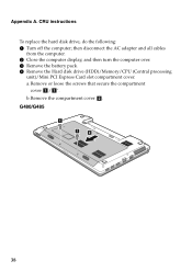
Appendix A. then disconnect the AC adapter and all cables from the computer. 2 Close the computer display, and then turn the computer over. 3 Remove the battery pack. 4 Remove the Hard disk drive (HDD)/Memory/CPU (Central processing unit)/Mini PCI Express Card slot compartment cover. b.Remove the compartment cover b. a.Remove or loose the screws that secure the compartment cover a/ a '. CRU instructions To replace the hard disk drive, do the following: 1 Turn off the computer; G480/G485 1 1 2 38
Appendix A. then disconnect the AC adapter and all cables from the computer. 2 Close the computer display, and then turn the computer over. 3 Remove the battery pack. 4 Remove the Hard disk drive (HDD)/Memory/CPU (Central processing unit)/Mini PCI Express Card slot compartment cover. b.Remove the compartment cover b. a.Remove or loose the screws that secure the compartment cover a/ a '. CRU instructions To replace the hard disk drive, do the following: 1 Turn off the computer; G480/G485 1 1 2 38
User Guide
Page 48
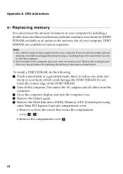
... / a '. However, the procedure for replacing the memory is the same as an option-in your computer. tricity in the memory slot of your computer. b.Remove the compartment cover b. 44 Note: • Use only the memory types supported by installing a double-data-rate three synchronous ...4 Remove the battery again. 5 Remove the Hard disk drive (HDD)/Memory/CPU (Central processing unit)/Mini PCI Express Card slot compartment cover. Appendix A. If you incorrectly install optional memory, or install an unsupported memory type, a warning beep will sound when you try to start the computer...
... / a '. However, the procedure for replacing the memory is the same as an option-in your computer. tricity in the memory slot of your computer. b.Remove the compartment cover b. 44 Note: • Use only the memory types supported by installing a double-data-rate three synchronous ...4 Remove the battery again. 5 Remove the Hard disk drive (HDD)/Memory/CPU (Central processing unit)/Mini PCI Express Card slot compartment cover. Appendix A. If you incorrectly install optional memory, or install an unsupported memory type, a warning beep will sound when you try to start the computer...
User Guide
Page 50
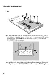
CRU instructions G780 1 1 ' 1 ' 1 1 ' 1 ' 2 6 If two DDR3 SDRAMs are already installed in the memory slot, remove one of them to save the old DDR3 SDRAM for the new one by pressing out on the latches on both edges of the socket and gently insert the DDR3 SDRAM into the socket at the same time. Be sure to make room for future use. 2 1 1 7 Align the notch of the DDR3 SDRAM with the protrusion of the socket at a 30-45° angle. 46 Appendix A.
CRU instructions G780 1 1 ' 1 ' 1 1 ' 1 ' 2 6 If two DDR3 SDRAMs are already installed in the memory slot, remove one of them to save the old DDR3 SDRAM for the new one by pressing out on the latches on both edges of the socket and gently insert the DDR3 SDRAM into the socket at the same time. Be sure to make room for future use. 2 1 1 7 Align the notch of the DDR3 SDRAM with the protrusion of the socket at a 30-45° angle. 46 Appendix A.
User Guide
Page 51
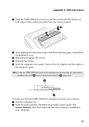
...the screws. A Reinstall the battery. The BIOS setup utility screen opens. Connect the AC adapter and the cables to the computer again. The System Memory item shows the total amount of the socket are servicing, the card must be installed in SLOT-0 ( : lower slot), but not in your computer...B Turn the computer over again. Note: If only one DDR3 SDRAM is installed correctly, do as follows: 1 Turn the computer on both edges of memory installed in SLOT-1 ( : upper slot). Appendix A. CRU instructions 8 Push the DDR3 SDRAM inward toward the socket until the latches on . 2 Hold F2 ...
...the screws. A Reinstall the battery. The BIOS setup utility screen opens. Connect the AC adapter and the cables to the computer again. The System Memory item shows the total amount of the socket are servicing, the card must be installed in SLOT-0 ( : lower slot), but not in your computer...B Turn the computer over again. Note: If only one DDR3 SDRAM is installed correctly, do as follows: 1 Turn the computer on both edges of memory installed in SLOT-1 ( : upper slot). Appendix A. CRU instructions 8 Push the DDR3 SDRAM inward toward the socket until the latches on . 2 Hold F2 ...
User Guide
Page 52
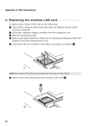
... and all cables from the computer. 2 Close the computer display, and then turn the computer over. 3 Remove the battery pack. 4 Remove the Hard disk drive/Memory/Central processing unit/Mini PCI Express Card slot compartment cover. 5 Disconnect the two wireless LAN cables (one black, one white) a . 1 Note: The wireless LAN card...
... and all cables from the computer. 2 Close the computer display, and then turn the computer over. 3 Remove the battery pack. 4 Remove the Hard disk drive/Memory/Central processing unit/Mini PCI Express Card slot compartment cover. 5 Disconnect the two wireless LAN cables (one black, one white) a . 1 Note: The wireless LAN card...
User Guide
Page 54
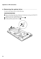
Appendix A. CRU instructions Removing the optical drive To remove the optical drive, do the following: G480/G485/G580/G585 1 Remove the Hard disk drive/Memory/Central processing unit/Mini PCI Express Card slot compartment cover. 2 Remove the screw shown in the illustration a . 3 Gently pull the optical drive out b . 1 2 50
Appendix A. CRU instructions Removing the optical drive To remove the optical drive, do the following: G480/G485/G580/G585 1 Remove the Hard disk drive/Memory/Central processing unit/Mini PCI Express Card slot compartment cover. 2 Remove the screw shown in the illustration a . 3 Gently pull the optical drive out b . 1 2 50
User Guide
Page 55
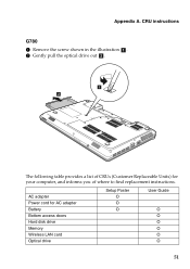
Appendix A. CRU instructions G780 1 Remove the screw shown in the illustration a . 2 Gently pull the optical drive out b . 1 2 The following table provides a list of where to find replacement instructions. AC adapter Power cord for your computer, and informs you of CRUs (Customer Replaceable Units) for AC adapter Battery Bottom access doors Hard disk drive Memory Wireless LAN card Optical drive Setup Poster O O O User Guide O O O O O O 51
Appendix A. CRU instructions G780 1 Remove the screw shown in the illustration a . 2 Gently pull the optical drive out b . 1 2 The following table provides a list of where to find replacement instructions. AC adapter Power cord for your computer, and informs you of CRUs (Customer Replaceable Units) for AC adapter Battery Bottom access doors Hard disk drive Memory Wireless LAN card Optical drive Setup Poster O O O User Guide O O O O O O 51


