Lenovo B575 Limited Warranty and Product Specific Notices V1.0
Page 13
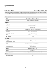
... HDD Keyboard Integrated Camera Battery AC Adapter I/O Ports HDMI (Select models only) USB Communication Audio Video Memory card slot Others Kensington slot Appr. 378 mm × 252 mm × 33.1 mm Appr. 2.35 kg with 6 cell battery AMD Brazos 18W E350 DDR3&#.../Mic-in jack VGA port × 1 6 in 1 slot × 1 (SD/SDHC/MMC/MS/MS PRO/xD) Yes 13 Lenovo reserves the right to improve and/or change specifications at any time without notice. Specifications Model Name: B575 Machine Type : 20119, 1450 Note: The following specifications may contain technical inaccuracies or typographical errors.
... HDD Keyboard Integrated Camera Battery AC Adapter I/O Ports HDMI (Select models only) USB Communication Audio Video Memory card slot Others Kensington slot Appr. 378 mm × 252 mm × 33.1 mm Appr. 2.35 kg with 6 cell battery AMD Brazos 18W E350 DDR3&#.../Mic-in jack VGA port × 1 6 in 1 slot × 1 (SD/SDHC/MMC/MS/MS PRO/xD) Yes 13 Lenovo reserves the right to improve and/or change specifications at any time without notice. Specifications Model Name: B575 Machine Type : 20119, 1450 Note: The following specifications may contain technical inaccuracies or typographical errors.
Lenovo B575 User Guide V1.0
Page 3
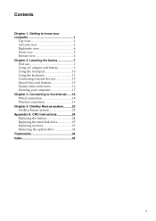
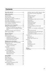
... 1 Left-side view 3 Right-side view 4 Front view 5 Bottom view 6 Chapter 2. CRU instructions 24 Replacing the battery 24 Replacing the hard disk drive 25 Replacing memory 29 Removing the optical drive 32 Trademarks 34 Index 35 i Getting to the Internet ......18 Wired connection 18 Wireless connection 19 Chapter 4. Connecting to know...
... 1 Left-side view 3 Right-side view 4 Front view 5 Bottom view 6 Chapter 2. CRU instructions 24 Replacing the battery 24 Replacing the hard disk drive 25 Replacing memory 29 Removing the optical drive 32 Trademarks 34 Index 35 i Getting to the Internet ......18 Wired connection 18 Wireless connection 19 Chapter 4. Connecting to know...
Lenovo B575 User Guide V1.0
Page 9
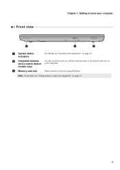
Insert memory cards (not supplied) here. b Integrated wireless device switch (Select models only) c Memory card slot Use this switch to know your computer. Chapter 1. Note: For details, see "System status indicators" on your computer Front view a System status indicators For details, see "Using memory cards (not supplied)" on page 13. 5 Getting to turn on/off the wireless radio of all wireless devices on page 16.
Insert memory cards (not supplied) here. b Integrated wireless device switch (Select models only) c Memory card slot Use this switch to know your computer. Chapter 1. Note: For details, see "System status indicators" on your computer Front view a System status indicators For details, see "Using memory cards (not supplied)" on page 13. 5 Getting to turn on/off the wireless radio of all wireless devices on page 16.

Lenovo B575 User Guide V1.0
Page 10
... disconnect the AC adapter and remove the battery pack. • For details, see "Using AC adapter and battery" on page 20. e Hard disk drive (HDD) / Memory / Mini PCI Express Card slot compartment 6 Insert a SIM card (not supplied) for using Mobile Broadband. spring loaded d SIM card slot (Select models only) The spring...
... disconnect the AC adapter and remove the battery pack. • For details, see "Using AC adapter and battery" on page 20. e Hard disk drive (HDD) / Memory / Mini PCI Express Card slot compartment 6 Insert a SIM card (not supplied) for using Mobile Broadband. spring loaded d SIM card slot (Select models only) The spring...
Lenovo B575 User Guide V1.0
Page 17
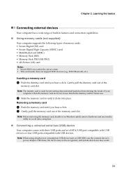
..., etc.). Retain the dummy card for preventing dust and small particles from entering the inside of the memory card slot. Removing a memory card 1 Push the memory card until you hear a click. 2 Gently pull the memory card out of memory cards: • Secure Digital (SD) card • Secure Digital High Capacity (SDHC) card ... (MS PRO) • xD-Picture (xD) card Notes: • Insert ONLY one card in use the external device's power adapter. Inserting a memory card 1 Push the dummy card until you hear a click. Note: When using a high power consumption USB device such as USB ODD, use . ...
..., etc.). Retain the dummy card for preventing dust and small particles from entering the inside of the memory card slot. Removing a memory card 1 Push the memory card until you hear a click. 2 Gently pull the memory card out of memory cards: • Secure Digital (SD) card • Secure Digital High Capacity (SDHC) card ... (MS PRO) • xD-Picture (xD) card Notes: • Insert ONLY one card in use the external device's power adapter. Inserting a memory card 1 Push the dummy card until you hear a click. Note: When using a high power consumption USB device such as USB ODD, use . ...
Lenovo B575 User Guide V1.0
Page 30
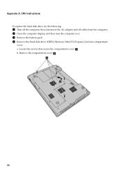
Appendix A. Loosen the screws that secure the compartment cover a . b. CRU instructions To replace the hard disk drive, do the following: 1 Turn off the computer; then disconnect the AC adapter and all cables from the computer. 2 Close the computer display, and then turn the computer over. 3 Remove the battery pack. 4 Remove the Hard disk drive (HDD)/Memory/Mini PCI Express Card slot compartment cover. a. Remove the compartment cover b . 26
Appendix A. Loosen the screws that secure the compartment cover a . b. CRU instructions To replace the hard disk drive, do the following: 1 Turn off the computer; then disconnect the AC adapter and all cables from the computer. 2 Close the computer display, and then turn the computer over. 3 Remove the battery pack. 4 Remove the Hard disk drive (HDD)/Memory/Mini PCI Express Card slot compartment cover. a. Remove the compartment cover b . 26
Lenovo B575 User Guide V1.0
Page 33
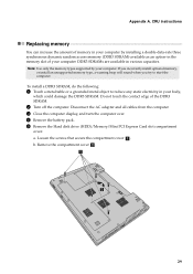
... computer. 3 Close the computer display, and turn the computer over. 4 Remove the battery pack. 5 Remove the Hard disk drive (HDD)/Memory/Mini PCI Express Card slot compartment cover. b. Do not touch the contact edge of your body, which could damage the DDR3 SDRAM. Note:... Use only the memory types supported by installing a double-data-rate three synchronous dynamic random access memory (DDR3 SDRAM)-available as an option-in various capacities. a. Remove the compartment cover b . 29 To install...
... computer. 3 Close the computer display, and turn the computer over. 4 Remove the battery pack. 5 Remove the Hard disk drive (HDD)/Memory/Mini PCI Express Card slot compartment cover. b. Do not touch the contact edge of your body, which could damage the DDR3 SDRAM. Note:... Use only the memory types supported by installing a double-data-rate three synchronous dynamic random access memory (DDR3 SDRAM)-available as an option-in various capacities. a. Remove the compartment cover b . 29 To install...
Lenovo B575 User Guide V1.0
Page 34
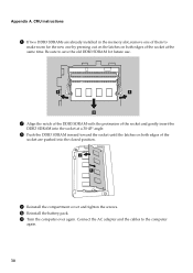
CRU instructions 6 If two DDR3 SDRAMs are already installed in the memory slot, remove one by pressing out on the latches on both edges of the socket at a 30-45° angle. 8 Push the DDR3 SDRAM inward ...
CRU instructions 6 If two DDR3 SDRAMs are already installed in the memory slot, remove one by pressing out on the latches on both edges of the socket at a 30-45° angle. 8 Push the DDR3 SDRAM inward ...
Lenovo B575 User Guide V1.0
Page 35
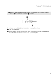
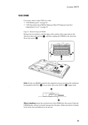
CRU instructions Note: If only one DDR3 SDRAM is installed correctly, do as follows: 1 Turn the computer on the computer you are servicing, the card must be installed in SLOT-0 ( : lower slot), but not in your computer. 31 The System Memory item shows the total amount of memory installed in SLOT-1 ( : upper slot). Appendix A. The BIOS setup utility screen opens. To make sure that the DDR3 SDRAM is used on . 2 Hold F2 during startup.
CRU instructions Note: If only one DDR3 SDRAM is installed correctly, do as follows: 1 Turn the computer on the computer you are servicing, the card must be installed in SLOT-0 ( : lower slot), but not in your computer. 31 The System Memory item shows the total amount of memory installed in SLOT-1 ( : upper slot). Appendix A. The BIOS setup utility screen opens. To make sure that the DDR3 SDRAM is used on . 2 Hold F2 during startup.

Lenovo B575 User Guide V1.0
Page 36
a. Loosen the screws that secure the compartment cover a . CRU instructions Removing the optical drive To remove the optical drive, do the following: 1 Turn off the computer; b. Remove the compartment cover b . 5 Remove the screw shown in the illustration c . 32 then disconnect the AC adapter and all cables from the computer. 2 Close the computer display, and then turn the computer over. 3 Remove the battery pack. 4 Remove the Hard disk drive (HDD)/Memory/Mini PCI Express Card slot compartment cover. Appendix A.
a. Loosen the screws that secure the compartment cover a . CRU instructions Removing the optical drive To remove the optical drive, do the following: 1 Turn off the computer; b. Remove the compartment cover b . 5 Remove the screw shown in the illustration c . 32 then disconnect the AC adapter and all cables from the computer. 2 Close the computer display, and then turn the computer over. 3 Remove the battery pack. 4 Remove the Hard disk drive (HDD)/Memory/Mini PCI Express Card slot compartment cover. Appendix A.
Lenovo B575 User Guide V1.0
Page 37
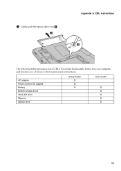
Appendix A. AC adapter Power cord for your computer, and informs you of where to find replacement instructions. CRU instructions The following table provides a list of CRUs (Customer Replaceable Units) for AC adapter Battery Bottom access doors Hard disk drive Memory Optical drive Setup Poster O O O User Guide O O O O O 33 6 Gently pull the optical drive out d .
Appendix A. AC adapter Power cord for your computer, and informs you of where to find replacement instructions. CRU instructions The following table provides a list of CRUs (Customer Replaceable Units) for AC adapter Battery Bottom access doors Hard disk drive Memory Optical drive Setup Poster O O O User Guide O O O O O 33 6 Gently pull the optical drive out d .
Hardware Maintenance Manual
Page 3
...23 Passwords 24 Power-on password 24 Supervisor password 24 Power management 25 Screen blank mode 25 Sleep (standby) mode 25 Hibernation mode 26 Lenovo B575 27 Specifications 27 Status indicators 29 Fn key combinations 31 FRU replacement notices 32 Screw notices 32 Removing and replacing an FRU 33 1010 Battery... pack 34 1020 Dummy card 35 1030 Hard disk drive(HDD)/Memory/Mini PCI Express Card slot compartment cover 36 1040 Hard disk drive 37 1050 Optical drive 38 1060 DIMM 39 1070 PCI Express Mini ...
...23 Passwords 24 Power-on password 24 Supervisor password 24 Power management 25 Screen blank mode 25 Sleep (standby) mode 25 Hibernation mode 26 Lenovo B575 27 Specifications 27 Status indicators 29 Fn key combinations 31 FRU replacement notices 32 Screw notices 32 Removing and replacing an FRU 33 1010 Battery... pack 34 1020 Dummy card 35 1030 Hard disk drive(HDD)/Memory/Mini PCI Express Card slot compartment cover 36 1040 Hard disk drive 37 1050 Optical drive 38 1060 DIMM 39 1070 PCI Express Mini ...
Hardware Maintenance Manual
Page 31
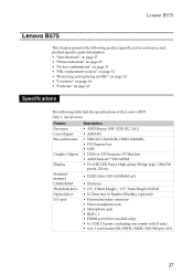
...XT Muxless • AMD Radeon™ HD 6470M Display • 15.6 HD LED Panel, High glossy Wedge type, 1366x768 pixels, 220 nit Standard memory • DDR3 1066/1333 SODIMM (x2) CMOS RAM • 256 bytes Hard disk drive • 2.5", 9.5mm Height / 2.5", 7mm Height ...8226; 4 x USB 2.0 ports ( including one combo with E-sata) • 6-in-1 card reader (SD/SDHC/MMC/MS/MS-pro/xD) 27 Lenovo B575 Lenovo B575 This chapter presents the following product-specific service references and product-specific parts information: • "Specifications" on page 27 • "Status indicators" on ...
...XT Muxless • AMD Radeon™ HD 6470M Display • 15.6 HD LED Panel, High glossy Wedge type, 1366x768 pixels, 220 nit Standard memory • DDR3 1066/1333 SODIMM (x2) CMOS RAM • 256 bytes Hard disk drive • 2.5", 9.5mm Height / 2.5", 7mm Height ...8226; 4 x USB 2.0 ports ( including one combo with E-sata) • 6-in-1 card reader (SD/SDHC/MMC/MS/MS-pro/xD) 27 Lenovo B575 Lenovo B575 This chapter presents the following product-specific service references and product-specific parts information: • "Specifications" on page 27 • "Status indicators" on ...
Hardware Maintenance Manual
Page 40
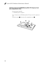
Lenovo B575 Hardware Maintenance Manual 1030 Hard disk drive(HDD)/Memory/Mini PCI Express Card slot compartment cover For access, remove this FRU: • "1010 Battery pack" on page 34 Figure 3. Removal steps of HDD/Memory/Mini PCI Express Card slot compartment cover Loosen five screws a , then remove the compartment cover b . 1 1 1 2 1 1 36
Lenovo B575 Hardware Maintenance Manual 1030 Hard disk drive(HDD)/Memory/Mini PCI Express Card slot compartment cover For access, remove this FRU: • "1010 Battery pack" on page 34 Figure 3. Removal steps of HDD/Memory/Mini PCI Express Card slot compartment cover Loosen five screws a , then remove the compartment cover b . 1 1 1 2 1 1 36
Hardware Maintenance Manual
Page 41
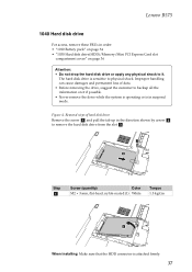
... 1.5 kgfcm 3 When installing: Make sure that the HDD connector is in order: • "1010 Battery pack" on page 34 • "1030 Hard disk drive(HDD)/Memory/Mini PCI Express Card slot compartment cover" on it . Removal steps of data. • Before removing the drive, suggest the customer to backup all the... hard disk drive is sensitive to it if possible. • Never remove the drive while the system is operating or is attached firmly. 37 Figure 4. Lenovo B575 1040 Hard disk drive For access, remove these FRUs in suspend mode.
... 1.5 kgfcm 3 When installing: Make sure that the HDD connector is in order: • "1010 Battery pack" on page 34 • "1030 Hard disk drive(HDD)/Memory/Mini PCI Express Card slot compartment cover" on it . Removal steps of data. • Before removing the drive, suggest the customer to backup all the... hard disk drive is sensitive to it if possible. • Never remove the drive while the system is operating or is attached firmly. 37 Figure 4. Lenovo B575 1040 Hard disk drive For access, remove these FRUs in suspend mode.
Hardware Maintenance Manual
Page 42
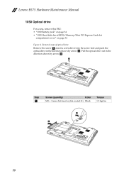
Pull the optical drive out in the direction shown by arrow c. 1 Step a Screw (quantity) Color M2 × 3 mm, flat-head, nylok-coated (1) Black Torque 1.5 kgfcm 2 3 38 Removal steps of optical drive Remove the screw a, insert a screwdriver into the screw hole and push the optical drive in the direction shown by arrow b. Lenovo B575 Hardware Maintenance Manual 1050 Optical drive For access, remove this FRU: • "1010 Battery pack" on page 34 • "1030 Hard disk drive(HDD)/Memory/Mini PCI Express Card slot compartment cover" on page 36 Figure 4.
Pull the optical drive out in the direction shown by arrow c. 1 Step a Screw (quantity) Color M2 × 3 mm, flat-head, nylok-coated (1) Black Torque 1.5 kgfcm 2 3 38 Removal steps of optical drive Remove the screw a, insert a screwdriver into the screw hole and push the optical drive in the direction shown by arrow b. Lenovo B575 Hardware Maintenance Manual 1050 Optical drive For access, remove this FRU: • "1010 Battery pack" on page 34 • "1030 Hard disk drive(HDD)/Memory/Mini PCI Express Card slot compartment cover" on page 36 Figure 4.
Hardware Maintenance Manual
Page 43
... of the DIMM into the place. Make sure that it snaps into the socket. Lenovo B575 1060 DIMM For access, remove these FRUs in order: • "1010 Battery pack" on page 34 • "1030 Hard disk drive(HDD)/Memory/Mini PCI Express Card slot compartment cover" on the computer you are servicing, the...
... of the DIMM into the place. Make sure that it snaps into the socket. Lenovo B575 1060 DIMM For access, remove these FRUs in order: • "1010 Battery pack" on page 34 • "1030 Hard disk drive(HDD)/Memory/Mini PCI Express Card slot compartment cover" on the computer you are servicing, the...
Hardware Maintenance Manual
Page 44
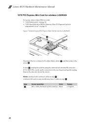
... them in order: • "1010 Battery pack" on page 34 • "1030 Hard disk drive(HDD)/Memory/Mini PCI Express Card slot compartment cover" on page 36 Figure 7. In step a, unplug the jacks by arrows. Lenovo B575 Hardware Maintenance Manual 1070 PCI Express Mini Card for wireless LAN/WAN 2 1 Disconnect the two wireless...
... them in order: • "1010 Battery pack" on page 34 • "1030 Hard disk drive(HDD)/Memory/Mini PCI Express Card slot compartment cover" on page 36 Figure 7. In step a, unplug the jacks by arrows. Lenovo B575 Hardware Maintenance Manual 1070 PCI Express Mini Card for wireless LAN/WAN 2 1 Disconnect the two wireless...

Hardware Maintenance Manual
Page 46
Lenovo B575 Hardware Maintenance Manual 1080 Keyboard For access, remove this FRU: • "1010 Battery pack" on page 34 • "1030 Hard disk drive(HDD)/Memory/Mini PCI Express Card slot compartment cover" on page 36 Figure 8. Removal steps of keyboard Remove three screws a. 1 1 1 Step a Screw (quantity) Color M2.5 × 8 mm, flat-head, nylok-coated (3) Black Torque 2.5 kgfcm 42
Lenovo B575 Hardware Maintenance Manual 1080 Keyboard For access, remove this FRU: • "1010 Battery pack" on page 34 • "1030 Hard disk drive(HDD)/Memory/Mini PCI Express Card slot compartment cover" on page 36 Figure 8. Removal steps of keyboard Remove three screws a. 1 1 1 Step a Screw (quantity) Color M2.5 × 8 mm, flat-head, nylok-coated (3) Black Torque 2.5 kgfcm 42

Hardware Maintenance Manual
Page 49
Removal steps of keyboard bezel Remove ten screws a and three screws b on page 42 Figure 9. Lenovo B575 1090 Keyboard bezel For access, remove these FRUs in order: • "1010 Battery pack" on page 34 • "1030 Hard disk drive(HDD)/Memory/Mini PCI Express Card slot compartment cover" on page 36 • "1050 Optical drive" on page 38 • "1080 Keyboard" on the bottom. 2 1 1 2 2 1 1 1 1 1 1 1 1 Step a b Screw (quantity) Color M2.5 × 8 mm, flat-head, nylok-coated (10) Black M2 × 2.5 mm, flat-head, nylok-coated (3) White Torque 2.5 kgfcm 1.5 kgfcm 45
Removal steps of keyboard bezel Remove ten screws a and three screws b on page 42 Figure 9. Lenovo B575 1090 Keyboard bezel For access, remove these FRUs in order: • "1010 Battery pack" on page 34 • "1030 Hard disk drive(HDD)/Memory/Mini PCI Express Card slot compartment cover" on page 36 • "1050 Optical drive" on page 38 • "1080 Keyboard" on the bottom. 2 1 1 2 2 1 1 1 1 1 1 1 1 Step a b Screw (quantity) Color M2.5 × 8 mm, flat-head, nylok-coated (10) Black M2 × 2.5 mm, flat-head, nylok-coated (3) White Torque 2.5 kgfcm 1.5 kgfcm 45


