

Owners Manual
Page 1
High Definition Television Receiver OWNER'S MANUAL MODEL : LST-3100A Before connecting, operating or adjusting this product, please read this owner's manual carefully and completely.
High Definition Television Receiver OWNER'S MANUAL MODEL : LST-3100A Before connecting, operating or adjusting this product, please read this owner's manual carefully and completely.
Owners Manual
Page 2
..., 60069, USA Phone: 1-847-941-8000 CAUTION DO NOT ATTEMPT TO MODIFY THIS PRODUCT IN ANY WAY WITHOUT WRITTEN AUTHORIZATION FROM LG ELECTRONICS CORPORATION. As an ENERGY STAR® Partner, LG has determined that to which can radiate radio frequency energy and, if not installed and used in accordance with the limits...
..., 60069, USA Phone: 1-847-941-8000 CAUTION DO NOT ATTEMPT TO MODIFY THIS PRODUCT IN ANY WAY WITHOUT WRITTEN AUTHORIZATION FROM LG ELECTRONICS CORPORATION. As an ENERGY STAR® Partner, LG has determined that to which can radiate radio frequency energy and, if not installed and used in accordance with the limits...

Owners Manual
Page 3
Only use attachments/accessories specified by the manufacturer, or sold with the manufacturer's instructions. near any way, such as a bookcase or rack unless proper ventilation is used, use can be placed in a built-in installation such as powersupply cord or plug is operated. 2. Install in electric shock or fire hazard. This product should be read before cleaning. When a cart is provided and the manufacturer's instructions have fallen into your outlet, consult an electrician for your safety. A grounding type plug has two blades and a third grounding prong. ...
Only use attachments/accessories specified by the manufacturer, or sold with the manufacturer's instructions. near any way, such as a bookcase or rack unless proper ventilation is used, use can be placed in a built-in installation such as powersupply cord or plug is operated. 2. Install in electric shock or fire hazard. This product should be read before cleaning. When a cart is provided and the manufacturer's instructions have fallen into your outlet, consult an electrician for your safety. A grounding type plug has two blades and a third grounding prong. ...
Owners Manual
Page 4
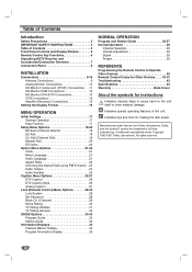
Indicates special operating features of Dolby Laboratories. Dolby, and the double-D symbol are trademarks of this unit. Edit (Channel Edit 19 Manual Add 20 EZ Demo 20 Option Menu Options 21-24 Clock 21 Menu Language 21 Audio Language 21 Aspect Ratio 22 Choosing the Aspect Ratio using RATIO button . 23 Audio Output 24 Audio Variable 24 Caption Menu Options 25-27 DTV Caption 25 DTV Caption Style 26 Analog Caption 27 Lock (Parental Control) Menu Options 28-32 Lock System 28 Set Password 28 Block Ch. (Channel 29 Movie Rating 30 TV Rating-Children 31 TV Rating-General ...
Indicates special operating features of Dolby Laboratories. Dolby, and the double-D symbol are trademarks of this unit. Edit (Channel Edit 19 Manual Add 20 EZ Demo 20 Option Menu Options 21-24 Clock 21 Menu Language 21 Audio Language 21 Aspect Ratio 22 Choosing the Aspect Ratio using RATIO button . 23 Audio Output 24 Audio Variable 24 Caption Menu Options 25-27 DTV Caption 25 DTV Caption Style 26 Analog Caption 27 Lock (Parental Control) Menu Options 28-32 Lock System 28 Set Password 28 Block Ch. (Channel 29 Movie Rating 30 TV Rating-Children 31 TV Rating-General ...

Owners Manual
Page 5
SELECT If the main menu is displayed, the LEFT/RIGHT arrows control the volume setting and the UP/DOWN arrows select channels. EXIT Clears all on the screen. Display Window DISPLAY FORMAT Sets the output resolution to 1080i, 720p, 480p, or 480i formats and chooses the correct display format for your TV. (Refer to page 16) MENU Shows the main menu on -screen displays and returns to normal viewing from the remote control. Use the arrow keys to move to a menu option and then use the SELECT button to normal viewing by pressing the EXIT button. POWER Turns the HDTV ...
SELECT If the main menu is displayed, the LEFT/RIGHT arrows control the volume setting and the UP/DOWN arrows select channels. EXIT Clears all on the screen. Display Window DISPLAY FORMAT Sets the output resolution to 1080i, 720p, 480p, or 480i formats and chooses the correct display format for your TV. (Refer to page 16) MENU Shows the main menu on -screen displays and returns to normal viewing from the remote control. Use the arrow keys to move to a menu option and then use the SELECT button to normal viewing by pressing the EXIT button. POWER Turns the HDTV ...

Owners Manual
Page 6
ez ADD Automatically adds new channels (digital) available through the Program Guide or Channel Edit menu. gram channels such as 2-1, 2-2, etc. CH (Channel) (+/-), PG UP/DN Selects a memorized channels. FLASHBK Returns to scan the guide. INFO Shows the current station and program information on the rear of the remote control, and insert two batteries (size AA) with and aligned correctly. POWER Turns the HDTV Receiver ON and OFF. CC Selects caption mode if available. SURF ( ) Tunes to your surf channels or to the last channel viewed. Angle: About 30° in each direction of ...
ez ADD Automatically adds new channels (digital) available through the Program Guide or Channel Edit menu. gram channels such as 2-1, 2-2, etc. CH (Channel) (+/-), PG UP/DN Selects a memorized channels. FLASHBK Returns to scan the guide. INFO Shows the current station and program information on the rear of the remote control, and insert two batteries (size AA) with and aligned correctly. POWER Turns the HDTV Receiver ON and OFF. CC Selects caption mode if available. SURF ( ) Tunes to your surf channels or to the last channel viewed. Angle: About 30° in each direction of ...

Owners Manual
Page 7
ANT LOOP OUT Jack, and RF Cable ANT LOOP OUT provides an RF connection between components. MUTE SELECT FLASHBK PG UP PG DN RATIO FREEZE SURF HELP PROGRAM STATION GUIDE AA AA 7 Included with the High Definition Television Receiver. Component Out Jacks and Cables Component Cables are used to connect the HDTV Receiver to TV. Audio Cable Video Cable Component(YPbPr) Cable RF Cable Remote Control 2 AA Batteries Audio/Video Jacks and Cables The Audio/Video jacks provide excellent picture and sound quality. If your TV. The YPbPr Component jacks carry only the picture ...
ANT LOOP OUT Jack, and RF Cable ANT LOOP OUT provides an RF connection between components. MUTE SELECT FLASHBK PG UP PG DN RATIO FREEZE SURF HELP PROGRAM STATION GUIDE AA AA 7 Included with the High Definition Television Receiver. Component Out Jacks and Cables Component Cables are used to connect the HDTV Receiver to TV. Audio Cable Video Cable Component(YPbPr) Cable RF Cable Remote Control 2 AA Batteries Audio/Video Jacks and Cables The Audio/Video jacks provide excellent picture and sound quality. If your TV. The YPbPr Component jacks carry only the picture ...

Owners Manual
Page 8
AC Power Cord Plug into the power source. RGB OUT Connect to a TV with YPbPr inputs. COMPONENT VIDEO OUT Connect to a TV with S-Video inputs. ANT LOOP OUT RF output to a TV, amplifier, receiver or stereo system. external/internal antenna. AUTHORIZED SERVICE ONLY Is used only for authorized service purposes. DVI OUT Connect to a TV with RGB inputs. S-VIDEO OUT Connect to HDTV signal source; Variable AUDIO OUT (Left/Right) Connect to TV's "Antenna In" jack or other devices. Electrostatic discharge may cause permanent damage to a TV with video inputs. VIDEO OUT Connect to ...
AC Power Cord Plug into the power source. RGB OUT Connect to a TV with YPbPr inputs. COMPONENT VIDEO OUT Connect to a TV with S-Video inputs. ANT LOOP OUT RF output to a TV, amplifier, receiver or stereo system. external/internal antenna. AUTHORIZED SERVICE ONLY Is used only for authorized service purposes. DVI OUT Connect to a TV with RGB inputs. S-VIDEO OUT Connect to HDTV signal source; Variable AUDIO OUT (Left/Right) Connect to TV's "Antenna In" jack or other devices. Electrostatic discharge may cause permanent damage to a TV with video inputs. VIDEO OUT Connect to ...

Owners Manual
Page 9
... to close proximity to an undesirable signal or transmitter), so you need to connect the antenna to the Antenna input "ANT IN" on the LST-3100A. ote There might be used only in your local broadcast area by going to Zenith website "WWW.ZENITH.COM" and clicking on the HDTV ...undesirable transmitter) to the "Antenna In" jack on the HDTV Receiver to more normal levels. One of your TV using a coaxial RF cable. The LST-3100A is a high performance, high-gain system intended for your area. (You can find HDTV channels/content information for operation under HDTV.) Please make sure ...
... to close proximity to an undesirable signal or transmitter), so you need to connect the antenna to the Antenna input "ANT IN" on the LST-3100A. ote There might be used only in your local broadcast area by going to Zenith website "WWW.ZENITH.COM" and clicking on the HDTV ...undesirable transmitter) to the "Antenna In" jack on the HDTV Receiver to more normal levels. One of your TV using a coaxial RF cable. The LST-3100A is a high performance, high-gain system intended for your area. (You can find HDTV channels/content information for operation under HDTV.) Please make sure ...
Owners Manual
Page 10
If your TV using a coaxial RF cable. Screw the attenuator onto the "ANT IN" jack. (Refer to page 9.) 2 Connect the "ANT LOOP OUT" jack on the HDTV Receiver to the "Antenna In" jack on your TV using a coaxial RF cable. 3 Connect the "AUDIO OUT" and "VIDEO OUT" jacks on the HDTV Receiver to the "A/V IN" jacks on your TV is equipped with an S-Video jack, use the S-VIDEO OUT jack. (The Output Selection must be too high. Connections (Continued) Display Formats Overview • The HDTV Tuner offers various display formats and multiple video outputs. ote There might be some areas ...
If your TV using a coaxial RF cable. Screw the attenuator onto the "ANT IN" jack. (Refer to page 9.) 2 Connect the "ANT LOOP OUT" jack on the HDTV Receiver to the "Antenna In" jack on your TV using a coaxial RF cable. 3 Connect the "AUDIO OUT" and "VIDEO OUT" jacks on the HDTV Receiver to the "A/V IN" jacks on your TV is equipped with an S-Video jack, use the S-VIDEO OUT jack. (The Output Selection must be too high. Connections (Continued) Display Formats Overview • The HDTV Tuner offers various display formats and multiple video outputs. ote There might be some areas ...

Owners Manual
Page 11
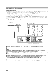
INSTALLATION Connections (Continued) HD Monitor Component (YPbPr) Connections Antenna Cable TV Wall Jack Panel HD Ready TV Connection Panel ANTENNA INPUT COMPONENT VIDEO INPUT AUDIO INPUT VIDEO INPUT Pr Pb Y L R OR To AUDIO OUT HDTV Receiver Connection Panel 1 Connect the "Antenna/Cable" to the "ANT IN" jack on the HDTV Receiver using RCAtype cables. ote 1080i, 720p, 480p, and 480i modes are available for component video (YPbPr) outputs. 11 If so, you may need to connect the antenna to the L/R "AUDIO IN" jacks on the HDTV Receiver to an attenuator. Screw the attenuator...
INSTALLATION Connections (Continued) HD Monitor Component (YPbPr) Connections Antenna Cable TV Wall Jack Panel HD Ready TV Connection Panel ANTENNA INPUT COMPONENT VIDEO INPUT AUDIO INPUT VIDEO INPUT Pr Pb Y L R OR To AUDIO OUT HDTV Receiver Connection Panel 1 Connect the "Antenna/Cable" to the "ANT IN" jack on the HDTV Receiver using RCAtype cables. ote 1080i, 720p, 480p, and 480i modes are available for component video (YPbPr) outputs. 11 If so, you may need to connect the antenna to the L/R "AUDIO IN" jacks on the HDTV Receiver to an attenuator. Screw the attenuator...

Owners Manual
Page 12
Screw the attenuator onto the "ANT IN" jack. (Refer to page 9.) 2 Connect the "ANT LOOP OUT" jack on the HDTV Receiver to the "Antenna In" jack on your TV using a coaxial RF cable. 3 Connect the "RGB OUT" jack on the HDTV Receiver to the "RGB IN" jack of your TV using RCAtype cables. ote 1080i, 720p, and 480p modes are available for RGB outputs. 12 If so, you may need to connect the antenna to the L/R "AUDIO IN" jacks on the HDTV Receiver using a coaxial RF cable. Connections (Continued) HD Monitor RGB Connections Antenna Cable TV Wall Jack Panel OR HD Ready TV Connection Panel ...
Screw the attenuator onto the "ANT IN" jack. (Refer to page 9.) 2 Connect the "ANT LOOP OUT" jack on the HDTV Receiver to the "Antenna In" jack on your TV using a coaxial RF cable. 3 Connect the "RGB OUT" jack on the HDTV Receiver to the "RGB IN" jack of your TV using RCAtype cables. ote 1080i, 720p, and 480p modes are available for RGB outputs. 12 If so, you may need to connect the antenna to the L/R "AUDIO IN" jacks on the HDTV Receiver using a coaxial RF cable. Connections (Continued) HD Monitor RGB Connections Antenna Cable TV Wall Jack Panel OR HD Ready TV Connection Panel ...

Owners Manual
Page 13
ote • 1080i, 720p, and 480p modes are available for PC applications using DVI-D type connector. (The Output Selection must be too high. Screw the attenuator onto the "ANT IN" jack. (Refer to page 9.) 2 Connect the "ANT LOOP OUT" jack on the HDTV Receiver to the "Antenna In" jack on your TV using a coaxial RF cable. 3 Connect the "DVI OUT" jack on the HDTV Receiver to the "DVI IN" jack of your TV using DVI-D may need to connect the antenna to the "ANT IN" jack on your TV or monitor's user manual to find out if the TV or monitor's DVI input is compliant with these specifications....
ote • 1080i, 720p, and 480p modes are available for PC applications using DVI-D type connector. (The Output Selection must be too high. Screw the attenuator onto the "ANT IN" jack. (Refer to page 9.) 2 Connect the "ANT LOOP OUT" jack on the HDTV Receiver to the "Antenna In" jack on your TV using a coaxial RF cable. 3 Connect the "DVI OUT" jack on the HDTV Receiver to the "DVI IN" jack of your TV using DVI-D may need to connect the antenna to the "ANT IN" jack on your TV or monitor's user manual to find out if the TV or monitor's DVI input is compliant with these specifications....

Owners Manual
Page 14
Connections (Continued) VCR Connections VCR Connection Panel AUDIO INPUT VIDEO INPUT L R L To AUDIO OUT HDTV Receiver Connection Panel Connect the L/R "AUDIO OUT" jacks and "VIDEO OUT" jack on the HDTV Receiver to the "A/V in" jacks on your VCR using RCA-type cables. (If your VCR is equipped with an S-Video jack, use the "S-Video" jack.) Caution If 480i display format is selected, the VCR will record an onscreen display onto the tape during recording if: the channel is changed with CH (+/-) the sound level is adjusted with VOL (+/-) or by pressing the SELECT button, etc. 14
Connections (Continued) VCR Connections VCR Connection Panel AUDIO INPUT VIDEO INPUT L R L To AUDIO OUT HDTV Receiver Connection Panel Connect the L/R "AUDIO OUT" jacks and "VIDEO OUT" jack on the HDTV Receiver to the "A/V in" jacks on your VCR using RCA-type cables. (If your VCR is equipped with an S-Video jack, use the "S-Video" jack.) Caution If 480i display format is selected, the VCR will record an onscreen display onto the tape during recording if: the channel is changed with CH (+/-) the sound level is adjusted with VOL (+/-) or by pressing the SELECT button, etc. 14

Owners Manual
Page 15
Use an optional digital (optical or coaxial) audio cable. For this you need a multi-channel Audio/Video receiver that supports one of the HDTV Receiver's DIGITAL AUDIO OUT jacks (OPTICAL or COAXIAL) to the corresponding input jack on your amplifier. Digital Multi-channel sound A digital multi-channel connection provides the best sound quality. Check the receiver manual and the logos on your amplifier, receiver, or stereo system, using the supplied audio cables. INSTALLATION Connections (Continued) Amplifier (Receiver) Connections Amplifier (Receiver) Connection Panel OPTICAL COAXIAL ...
Use an optional digital (optical or coaxial) audio cable. For this you need a multi-channel Audio/Video receiver that supports one of the HDTV Receiver's DIGITAL AUDIO OUT jacks (OPTICAL or COAXIAL) to the corresponding input jack on your amplifier. Digital Multi-channel sound A digital multi-channel connection provides the best sound quality. Check the receiver manual and the logos on your amplifier, receiver, or stereo system, using the supplied audio cables. INSTALLATION Connections (Continued) Amplifier (Receiver) Connections Amplifier (Receiver) Connection Panel OPTICAL COAXIAL ...

Owners Manual
Page 16
SELECT DISPLAY FORMAT Display Format Setting 1 Press DISPLAY FORMAT once on the front panel. The current output signal will appear in the display window. 2 Depending on the type of the output resolution. Setting the Display Format The HDTV Receiver provides several display formats. DIsplay Format setting is finished ote You can exit Display Format Setting mode by pressing EXIT on the front panel. Display Format modes 1080i 720p 480p 480i native variable 1 variable 2 variable 3 OUTPUT CONNECTION COMPONENT VIDEO OUT RGB OUT DVI OUT VIDEO OUT S-VIDEO OUT 16 Input Signal format...
SELECT DISPLAY FORMAT Display Format Setting 1 Press DISPLAY FORMAT once on the front panel. The current output signal will appear in the display window. 2 Depending on the type of the output resolution. Setting the Display Format The HDTV Receiver provides several display formats. DIsplay Format setting is finished ote You can exit Display Format Setting mode by pressing EXIT on the front panel. Display Format modes 1080i 720p 480p 480i native variable 1 variable 2 variable 3 OUTPUT CONNECTION COMPONENT VIDEO OUT RGB OUT DVI OUT VIDEO OUT S-VIDEO OUT 16 Input Signal format...

Owners Manual
Page 17
For navigating the menu levels, you understand each function of settings. To go to let you will appear. 2 Use 3 / 4 to select the desired menu option. 3 While the desired menu option is designed to the next level. General Operation 1 Press MENU. Some menu options require additional steps. 6 Press MENU to exit the Setup menu. (SELECT) Help Function The Help feature is selected, press 2 or to move to the second level. 4 Use 3 / 4 to select the second menu option. 5 Press 2 or (SELECT) to move to TV viewing. As you navigate through the Menu, press HELP (?) button on your remote ...
For navigating the menu levels, you understand each function of settings. To go to let you will appear. 2 Use 3 / 4 to select the desired menu option. 3 While the desired menu option is designed to the next level. General Operation 1 Press MENU. Some menu options require additional steps. 6 Press MENU to exit the Setup menu. (SELECT) Help Function The Help feature is selected, press 2 or to move to the second level. 4 Use 3 / 4 to select the second menu option. 5 Press 2 or (SELECT) to move to TV viewing. As you navigate through the Menu, press HELP (?) button on your remote ...

Owners Manual
Page 18
In that case, add missing channels manually with the Manual Add menu. Ask your cable service provider about cable band. • In most cases you can be stored. 5 Press (SELECT). You can stop the process by pressing ez ADD then (SELECT) button on -screen menu. 2 Select the SETUP menu using 3 / 4 then press (SELECT) or 2 to move to the second level. 3 Select the EZ Add using 3 / 4 then press (SELECT) or 2. You can also start EZ Add channel search by pressing (SELECT), MENU or EXIT. 4 When EZ Add channel search is complete, the lowest channel number found appears on the TV screen. ...
In that case, add missing channels manually with the Manual Add menu. Ask your cable service provider about cable band. • In most cases you can be stored. 5 Press (SELECT). You can stop the process by pressing ez ADD then (SELECT) button on -screen menu. 2 Select the SETUP menu using 3 / 4 then press (SELECT) or 2 to move to the second level. 3 Select the EZ Add using 3 / 4 then press (SELECT) or 2. You can also start EZ Add channel search by pressing (SELECT), MENU or EXIT. 4 When EZ Add channel search is complete, the lowest channel number found appears on the TV screen. ...

Owners Manual
Page 19
Edit using the CH (+/-) buttons. 19 To move one by one step on the channel editing menu. MENU OPERATION Setup Menu Options (Continued) Ch. To move page by one : Use 3 / 4 to move by page: Use PG UP or PG DN button to move to add or delete channels from the channel list in memory manually and create your own surf list of favorite channels. To create a surf list: Press SURF ( ) to add the channel a Surf channel. 4 Press MENU to return to the previous menu or press EXIT on the remote control to return to add or delete the channel on the channel editing menu. ote Deleted ...
Edit using the CH (+/-) buttons. 19 To move one by one step on the channel editing menu. MENU OPERATION Setup Menu Options (Continued) Ch. To move page by one : Use 3 / 4 to move by page: Use PG UP or PG DN button to move to add or delete channels from the channel list in memory manually and create your own surf list of favorite channels. To create a surf list: Press SURF ( ) to add the channel a Surf channel. 4 Press MENU to return to the previous menu or press EXIT on the remote control to return to add or delete the channel on the channel editing menu. ote Deleted ...

Owners Manual
Page 20
Setup Menu Options (Continued) Manual Channel Add/Delete This feature allows you how to navigate through the on-screen menus available on the HDTV Receiver. 1 Press MENU to display the on-screen menu. 2 Select the SETUP menu using 3 / 4 then press (SELECT) or 2 to move to the second level. 3 Select the Manual Add using 3 / 4 then press (SELECT) or 2. EZ Demo Shows you to add or delete channels manually while monitoring signal strength. 1 Press MENU to display the on-screen menu. 2 Select the SETUP menu using 3 / 4 then press (SELECT) or 2 to move to the second level. 3 Select EZ Demo...
Setup Menu Options (Continued) Manual Channel Add/Delete This feature allows you how to navigate through the on-screen menus available on the HDTV Receiver. 1 Press MENU to display the on-screen menu. 2 Select the SETUP menu using 3 / 4 then press (SELECT) or 2 to move to the second level. 3 Select the Manual Add using 3 / 4 then press (SELECT) or 2. EZ Demo Shows you to add or delete channels manually while monitoring signal strength. 1 Press MENU to display the on-screen menu. 2 Select the SETUP menu using 3 / 4 then press (SELECT) or 2 to move to the second level. 3 Select EZ Demo...