Owner's Manual
Page 5
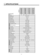
SPECIFICATIONS GENERAL FEATURES MODELS LSC27914SB /01 LSC27914SW /01 LSC27914TT /01 LSC27914ST /01 FREEZER REFRIGERATOR SPECIFICATIONS Color Dimensions Net Weight Capacity Refrigerant Climate class Rated Rating Cooling System Temperature Control Defrosting System Insulation Compressor Evaporator Condenser Lubricanting Oil Drier Capillary Tube First Defrost Defrost Cycle Desfrosting Device Anti-freezing Heater Case Material Door Material...
SPECIFICATIONS GENERAL FEATURES MODELS LSC27914SB /01 LSC27914SW /01 LSC27914TT /01 LSC27914ST /01 FREEZER REFRIGERATOR SPECIFICATIONS Color Dimensions Net Weight Capacity Refrigerant Climate class Rated Rating Cooling System Temperature Control Defrosting System Insulation Compressor Evaporator Condenser Lubricanting Oil Drier Capillary Tube First Defrost Defrost Cycle Desfrosting Device Anti-freezing Heater Case Material Door Material...
Owner's Manual
Page 22
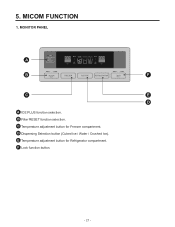
F Lock function button. - 21 - B Filter RESET function selection. E Temperature adjustment button for Freezer compartment. MONITOR PANEL A B F C E D A ICE PLUS function selection. MICOM FUNCTION 1. C Temperature adjustment button for Refrigerator compartment. D Dispensing Selection button (Cubed Ice / Water / Crushed Ice). 5.
F Lock function button. - 21 - B Filter RESET function selection. E Temperature adjustment button for Freezer compartment. MONITOR PANEL A B F C E D A ICE PLUS function selection. MICOM FUNCTION 1. C Temperature adjustment button for Refrigerator compartment. D Dispensing Selection button (Cubed Ice / Water / Crushed Ice). 5.
Owner's Manual
Page 23
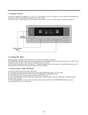
...then press and hold ICE PLUS and REFRIGERATOR button over 5 seconds. 3) The display will show the word "OFF" in Freezer and Refrigerator Temperature level. 4) In this mode all loads are always OFF except to work normally (even in demonstration mode the refrigerator Lamp automatic off (Compressor... mode. 2) To activate this mode press and hold ICE PLUS and REFRIGERATOR button over 5 seconds (Display return to the previously controlled temperature. Press FREEZER and ICE PLUS buttons simultaneously to turn ON all leds are turned off function works normally) 6) To exit Demonstration mode ...
...then press and hold ICE PLUS and REFRIGERATOR button over 5 seconds. 3) The display will show the word "OFF" in Freezer and Refrigerator Temperature level. 4) In this mode all loads are always OFF except to work normally (even in demonstration mode the refrigerator Lamp automatic off (Compressor... mode. 2) To activate this mode press and hold ICE PLUS and REFRIGERATOR button over 5 seconds (Display return to the previously controlled temperature. Press FREEZER and ICE PLUS buttons simultaneously to turn ON all leds are turned off function works normally) 6) To exit Demonstration mode ...
Owner's Manual
Page 25
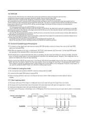
...motor, turn ON or OFF. 3) If there is a power outage and the refrigerator is running at the lowest temperature. Then a failure code will be reduced to failure diagnosis function table) on again, ICE PLUS will complete its.... (5) The fan motor in the freezer compartment runs at the lowest temperature. 1-9. After 24 hours or if the ICE PLUS key is pressed again, the freezer will return to ...its previous temperature. 5) During the first 3 hours: (1) Compressor and freezer fan (HIGH RPM) run continuously. (2)...
...motor, turn ON or OFF. 3) If there is a power outage and the refrigerator is running at the lowest temperature. Then a failure code will be reduced to failure diagnosis function table) on again, ICE PLUS will complete its.... (5) The fan motor in the freezer compartment runs at the lowest temperature. 1-9. After 24 hours or if the ICE PLUS key is pressed again, the freezer will return to ...its previous temperature. 5) During the first 3 hours: (1) Compressor and freezer fan (HIGH RPM) run continuously. (2)...
Owner's Manual
Page 27
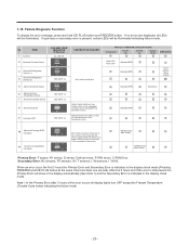
...CODE INDICATOR (F-Section) ALL LED ON CONTENTS OF FAILURE - 3 Abnormal Refrigerator Sensor (1) 4 Abnormal Refrigerator Sensor (2) 5 Abnormal Defrost Sensor 6 Abnormal Room Temperature Sensor 7 Abnormal Icemaker Sensor 8 Abnormal Defrost 9 Icemaker UNIT SEE NOTE (1) Cut o short circuit wire SEE NOTE (1) SEE NOTE (1) SEE NOTE ... first 3 hours the Primary Error and Secondary Error is no errors are displayed, all display lights turn OFF except the Freezer Temperature (Trouble Code Index) indicating the failure mode. - 26 - 1-16. Faulty Icemkaer unit, Motor or Hall IC; Lead ...
...CODE INDICATOR (F-Section) ALL LED ON CONTENTS OF FAILURE - 3 Abnormal Refrigerator Sensor (1) 4 Abnormal Refrigerator Sensor (2) 5 Abnormal Defrost Sensor 6 Abnormal Room Temperature Sensor 7 Abnormal Icemaker Sensor 8 Abnormal Defrost 9 Icemaker UNIT SEE NOTE (1) Cut o short circuit wire SEE NOTE (1) SEE NOTE (1) SEE NOTE ... first 3 hours the Primary Error and Secondary Error is no errors are displayed, all display lights turn OFF except the Freezer Temperature (Trouble Code Index) indicating the failure mode. - 26 - 1-16. Faulty Icemkaer unit, Motor or Hall IC; Lead ...
Owner's Manual
Page 28
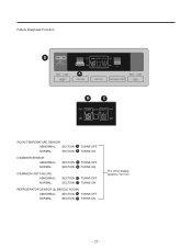
Failure Diagnosis Function D A B C ROOM TEMPERATURE SENSOR ABNORMAL: SECTION A TURNS OFF NORMAL: SECTION A TURNS ON ICEMAKER SENSOR ABNORMAL: NORMAL: SECTION B TURNS OFF SECTION B TURNS ON ICEMAKER UNIT FAILURE ABNORMAL: NORMAL: SECTION C TURNS OFF SECTION C TURNS ON REFRIGERATOR SENSOR (2) [MIDDLE ROOM] ABNORMAL: SECTION D TURNS OFF NORMAL: SECTION D TURNS ON The other display graphics Turn On - 27 -
Failure Diagnosis Function D A B C ROOM TEMPERATURE SENSOR ABNORMAL: SECTION A TURNS OFF NORMAL: SECTION A TURNS ON ICEMAKER SENSOR ABNORMAL: NORMAL: SECTION B TURNS OFF SECTION B TURNS ON ICEMAKER UNIT FAILURE ABNORMAL: NORMAL: SECTION C TURNS OFF SECTION C TURNS ON REFRIGERATOR SENSOR (2) [MIDDLE ROOM] ABNORMAL: SECTION D TURNS OFF NORMAL: SECTION D TURNS ON The other display graphics Turn On - 27 -

Owner's Manual
Page 36
Switch entry circuit The following circuits are sensing signal form the test switch, damper motor reed switch for testing and diagnosing the refrigerator. IC1 P67 63 MICOM CC10* 104 R84* 2K R28* 4.7K SW1 - 35 - 1-5. Temperature sensing circuit A A B BC C D DE E F F ITEM A B C D E F SENSOR RT F D R1 R2 I/M LOCATION CON5 PIN4,5 CON6 PIN1,2 CON6 PIN3,4 CON7 PIN5,6 CON7 PIN7,8 CON8 PIN1,2 COLOR 2*WH 2*WH 2*BO 2*WH 2*GY 2*GY 1-6.
Switch entry circuit The following circuits are sensing signal form the test switch, damper motor reed switch for testing and diagnosing the refrigerator. IC1 P67 63 MICOM CC10* 104 R84* 2K R28* 4.7K SW1 - 35 - 1-5. Temperature sensing circuit A A B BC C D DE E F F ITEM A B C D E F SENSOR RT F D R1 R2 I/M LOCATION CON5 PIN4,5 CON6 PIN1,2 CON6 PIN3,4 CON7 PIN5,6 CON7 PIN7,8 CON8 PIN1,2 COLOR 2*WH 2*WH 2*BO 2*WH 2*GY 2*GY 1-6.

Owner's Manual
Page 40
... this appliance family. - 39 - The value for the freezer is the same for adjusting the appliance. This circuit enters the necessary level of the refrigerator. Temperature compensation table at the refrigerator is as follows: Modification resistance Current 470 resistance 2 k 3.3 k 5.6 k 8.2 k 10 k 12 k 18 k 33 k 56 k 180 k No ... [7.2 °F] [6.3 °F] [5.4 °F] [4.5 °F] [3.6 °F] [2.7 °F] [1.8 °F] [0.9 °F] Down Down Down Down Down Down Down Down Down Down change Temperature compensation at the freezer is performed the same as at the refrigerator.
... this appliance family. - 39 - The value for the freezer is the same for adjusting the appliance. This circuit enters the necessary level of the refrigerator. Temperature compensation table at the refrigerator is as follows: Modification resistance Current 470 resistance 2 k 3.3 k 5.6 k 8.2 k 10 k 12 k 18 k 33 k 56 k 180 k No ... [7.2 °F] [6.3 °F] [5.4 °F] [4.5 °F] [3.6 °F] [2.7 °F] [1.8 °F] [0.9 °F] Down Down Down Down Down Down Down Down Down Down change Temperature compensation at the freezer is performed the same as at the refrigerator.
Owner's Manual
Page 41
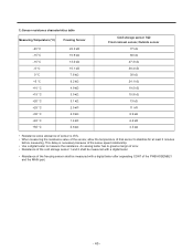
This delay is ±5%. • When measuring the resistance value of the sensor, allow the temperature of that sensor to stabilize for at least 3 minutes before measuring. An analog tester has to great a margin of error. • Resistance of ... freezing sensor shall be measured with a digital tester after separating CON7 of the PWB ASSEMBLY and the MAIN part. - 40 - 1) Sensor resistance characteristics table Measuring Temperature (°C) -20 °C -15 °C -15 °C -5 °C 0 °C +5 °C +10 °C +15 °C +20 °C +25 °C +30 °C +40 °C +50 &#...
This delay is ±5%. • When measuring the resistance value of the sensor, allow the temperature of that sensor to stabilize for at least 3 minutes before measuring. An analog tester has to great a margin of error. • Resistance of ... freezing sensor shall be measured with a digital tester after separating CON7 of the PWB ASSEMBLY and the MAIN part. - 40 - 1) Sensor resistance characteristics table Measuring Temperature (°C) -20 °C -15 °C -15 °C -5 °C 0 °C +5 °C +10 °C +15 °C +20 °C +25 °C +30 °C +40 °C +50 &#...

Owner's Manual
Page 50
ICEMAKER TROUBLESHOOTING It is possible to confirm by pressing freezer and refrigerator temperature control buttons for more than 1 second (icemaker is normal if all LEDs are ON): refer to trouble diagnosis function in MICOM. 8. (Pin No. 22 of IC1) 8 • • 44 • • 8 • 19 • 8 • • • - 49 - 3.
ICEMAKER TROUBLESHOOTING It is possible to confirm by pressing freezer and refrigerator temperature control buttons for more than 1 second (icemaker is normal if all LEDs are ON): refer to trouble diagnosis function in MICOM. 8. (Pin No. 22 of IC1) 8 • • 44 • • 8 • 19 • 8 • • • - 49 - 3.
Owner's Manual
Page 54
... the air. - Too much . clogged. Performed. Caps are missed. Moisture penetration. Drier angle. During rest time. During transportation. No electric power on package condition. Drier temperature. Short pipe insert. Too short time. Squeezed. • The evaporator does not cool from the beginning (no evidence of moisture attached).
... the air. - Too much . clogged. Performed. Caps are missed. Moisture penetration. Drier angle. During rest time. During transportation. No electric power on package condition. Drier temperature. Short pipe insert. Too short time. Squeezed. • The evaporator does not cool from the beginning (no evidence of moisture attached).
Owner's Manual
Page 57
...too much or too little. A screw or other foreign material has fallen into the drip tray or damper. Characteristics of temperature - Bad characteristics of charging cylinder. Insufficient motor RPM Fan overload. - Bent. Malfunction of its own temperatue. The EPS.... 4) No cooling air circulation. Accumulated residual frost. Rated power misuse. Low voltage. Faulty fan. Fan misuse. Wrong setting of temperature controller. - No contact of refrigerant. Position of cooling air. - 56 - Small cooling air discharge. Foreign materials Adiabatics liquid dump...
...too much or too little. A screw or other foreign material has fallen into the drip tray or damper. Characteristics of temperature - Bad characteristics of charging cylinder. Insufficient motor RPM Fan overload. - Bent. Malfunction of its own temperatue. The EPS.... 4) No cooling air circulation. Accumulated residual frost. Rated power misuse. Low voltage. Faulty fan. Fan misuse. Wrong setting of temperature controller. - No contact of refrigerant. Position of cooling air. - 56 - Small cooling air discharge. Foreign materials Adiabatics liquid dump...
Owner's Manual
Page 58
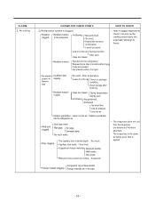
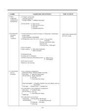
... 2) Condensation in freeezer compartment. Cool air leak Not fully filled. and transmitted. Out plate Ref/Lower part. Warm refrigerator compartment temperature. Adiabatics dump liquid. 2) Food storate. Door open. Faulty contact. Space is secluded. • Inspect parts measurements and check...Button is too much. Food hinders door closing . Gasket gap. - 57- CLAIMS. 4. Packages block air flow. High ambient temperature. CAUSES AND CHECK POINTS. 1) Colgged cooling path. Store too much food. Too much at strong . Gap around gasket. --...
... 2) Condensation in freeezer compartment. Cool air leak Not fully filled. and transmitted. Out plate Ref/Lower part. Warm refrigerator compartment temperature. Adiabatics dump liquid. 2) Food storate. Door open. Faulty contact. Space is secluded. • Inspect parts measurements and check...Button is too much. Food hinders door closing . Gasket gap. - 57- CLAIMS. 4. Packages block air flow. High ambient temperature. CAUSES AND CHECK POINTS. 1) Colgged cooling path. Store too much food. Too much at strong . Gap around gasket. --...

Owner's Manual
Page 62
... out. HOW TO CHECK 2) Odor. Structure, appearance, and others. 1) Door foam. Not closed (faulty stopper). compartment is Bad freezer compartment door opened when freezer assembly. Temperature of fragrant foods. Deodorizer. Food Storage. Long term storage. compartment is No stopper. Others. Odors from cleaners or items which shroud not be stored in...
... out. HOW TO CHECK 2) Odor. Structure, appearance, and others. 1) Door foam. Not closed (faulty stopper). compartment is Bad freezer compartment door opened when freezer assembly. Temperature of fragrant foods. Deodorizer. Food Storage. Long term storage. compartment is No stopper. Others. Odors from cleaners or items which shroud not be stored in...
Owner's Manual
Page 64
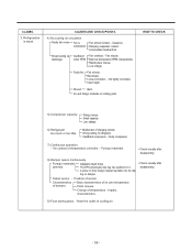
TEMPERATURE - 63 - Fan icing: Confirm visually. - Press button to check operation. - Faulty button pressure and contact: Press button to check - button: Check visually. - Door ... Remove dust and contaminants compressor compartment. Remove the dust with a fan motor. 2-3. Wire is off. - Iced button (faulty) operation: - Problems Causes Checks Measures Remarks High temperature in compressor compartment. - Door sag: fix door. Bad radiation conditions in the freezer compartment. from the coils condenser while the refrigerator is cut . - Poor cool...
TEMPERATURE - 63 - Fan icing: Confirm visually. - Press button to check operation. - Faulty button pressure and contact: Press button to check - button: Check visually. - Door ... Remove dust and contaminants compressor compartment. Remove the dust with a fan motor. 2-3. Wire is off. - Iced button (faulty) operation: - Problems Causes Checks Measures Remarks High temperature in compressor compartment. - Door sag: fix door. Bad radiation conditions in the freezer compartment. from the coils condenser while the refrigerator is cut . - Poor cool...

Owner's Manual
Page 78
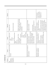
... resistance value. 3 Result 0 Ù Short Service Action Go to Step 3 OFF Open Go to Step 4 Other Normal Check the Temperature and Resistance (Temperature Chart #1) Go to Step 6 Temperatures when unit is energized (Refer to Temperature Chart #1) Result 0 Ù Short OFF Open Service Action Replace Product Change the sensor - 77 - Troubleshooting With Error Display 1) Abnormal...
... resistance value. 3 Result 0 Ù Short Service Action Go to Step 3 OFF Open Go to Step 4 Other Normal Check the Temperature and Resistance (Temperature Chart #1) Go to Step 6 Temperatures when unit is energized (Refer to Temperature Chart #1) Result 0 Ù Short OFF Open Service Action Replace Product Change the sensor - 77 - Troubleshooting With Error Display 1) Abnormal...

Owner's Manual
Page 79
1) Abnormal Freezer Sensor Error NO. CHECKING FLOW 1) Remove the Cover sensor. 2) Cut sensor and stripe terminals. 3) Make a short in striped terminals. 4) Maker measurement. 4 RESULT & SERVICE ACTION Result 0 Ù Short OFF Open Service Action Change the sensor Replace Product 5 Resistance Values are according to Temperature Chart table? 6 Result YES Normal Same Service Action Explain to costumer Replace Main PCB ERROR Different Proceed acord the displayed error Result YES Normal Sensor NO Abnormal Sensor Service Action Replace Main PCB Replace Sensor - 78 -
1) Abnormal Freezer Sensor Error NO. CHECKING FLOW 1) Remove the Cover sensor. 2) Cut sensor and stripe terminals. 3) Make a short in striped terminals. 4) Maker measurement. 4 RESULT & SERVICE ACTION Result 0 Ù Short OFF Open Service Action Change the sensor Replace Product 5 Resistance Values are according to Temperature Chart table? 6 Result YES Normal Same Service Action Explain to costumer Replace Main PCB ERROR Different Proceed acord the displayed error Result YES Normal Sensor NO Abnormal Sensor Service Action Replace Main PCB Replace Sensor - 78 -

Owner's Manual
Page 80
... check between White to White as is shown in the picture. 2 Result 0 Ù Short OFF Open Other Normal Service Action Go to Step 3 Check the Temperature and Resistance (Temperature Chart #2) Go to Step 7 1) Remove the Control Box in Refrigerator sensor. CHECKING FLOW Check for any damage.
... check between White to White as is shown in the picture. 2 Result 0 Ù Short OFF Open Other Normal Service Action Go to Step 3 Check the Temperature and Resistance (Temperature Chart #2) Go to Step 7 1) Remove the Control Box in Refrigerator sensor. CHECKING FLOW Check for any damage.

Owner's Manual
Page 81
... & SERVICE ACTION Go to Step 5. 4 Unplug connector in the picture. 5 Result 0 Ù Short OFF Open Service Action Replace Product Go to Temperature Chart table? 7 - 80 - Check the Temperature and Resistance (Temperature Chart #2) Go to Step 7 Resistance Values are according to Step 6 1) Remove the Control Box in Refrigerator sensor. 6 Check resistance value between White...
... & SERVICE ACTION Go to Step 5. 4 Unplug connector in the picture. 5 Result 0 Ù Short OFF Open Service Action Replace Product Go to Temperature Chart table? 7 - 80 - Check the Temperature and Resistance (Temperature Chart #2) Go to Step 7 Resistance Values are according to Step 6 1) Remove the Control Box in Refrigerator sensor. 6 Check resistance value between White...

Owner's Manual
Page 82
3) Abnormal Refrigerator Sensor Error (2) NO. CHECKING FLOW Check for a loose connection. 1 RESULT & SERVICE ACTION Result Firmly plugged Loose Service Action Go to Step 2 Unplug connector in CON 7 and check between Gray to Gray as is shown in the picture. 2 Result 0 Ù Short OFF Open Other Normal Service Action Go to Step 3 Go to Step 4 Check the Temperature and Resistance (Temperature Chart #2) Go to Step 6 1) Remove Cover sensor. 2) Cut sensor and check resistance value. 3 Result 0 Ù Short OFF Open Service Action Replace Product Change Sensor - 81 -
3) Abnormal Refrigerator Sensor Error (2) NO. CHECKING FLOW Check for a loose connection. 1 RESULT & SERVICE ACTION Result Firmly plugged Loose Service Action Go to Step 2 Unplug connector in CON 7 and check between Gray to Gray as is shown in the picture. 2 Result 0 Ù Short OFF Open Other Normal Service Action Go to Step 3 Go to Step 4 Check the Temperature and Resistance (Temperature Chart #2) Go to Step 6 1) Remove Cover sensor. 2) Cut sensor and check resistance value. 3 Result 0 Ù Short OFF Open Service Action Replace Product Change Sensor - 81 -


