Owner's Manual
Page 3
...50 8. CIRCUIT DIAGRAM...51 9. Freezer Shelf...8 5. Fan Shroud Grille...14 5. Monitor Panel...21 6. Explanation for PCB circuit 30 7. ICEMAKER AND DISPENSER WORKING PRINCIPLES AND REPAIR 45 1. DISASSEMBLY ...6 1. Disassemble of Tray Drip 18 10. Ice maker Troubleshooting 49 4. SPECIFICATIONS ...4 2. Door Alignment...6 2. HOW TO DISASSEMBLY AND ASSEMBLY 11 1. How to ice maker 9 4. Water Valve Disassembly Method 15 7. Disassemble of fan Motor 17 9. Refrigerator Shelves...8 4. EXPLODED VIEW ...132 - 2 - Water Valve Tubes Assembly Method 16...
...50 8. CIRCUIT DIAGRAM...51 9. Freezer Shelf...8 5. Fan Shroud Grille...14 5. Monitor Panel...21 6. Explanation for PCB circuit 30 7. ICEMAKER AND DISPENSER WORKING PRINCIPLES AND REPAIR 45 1. DISASSEMBLY ...6 1. Disassemble of Tray Drip 18 10. Ice maker Troubleshooting 49 4. SPECIFICATIONS ...4 2. Door Alignment...6 2. HOW TO DISASSEMBLY AND ASSEMBLY 11 1. How to ice maker 9 4. Water Valve Disassembly Method 15 7. Disassemble of fan Motor 17 9. Refrigerator Shelves...8 4. EXPLODED VIEW ...132 - 2 - Water Valve Tubes Assembly Method 16...
Owner's Manual
Page 5
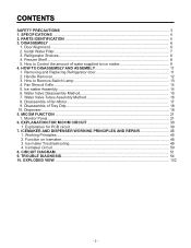
1. SPECIFICATIONS GENERAL FEATURES MODELS LSC27914SB /01 LSC27914SW /01 LSC27914TT /01 LSC27914ST /01 FREEZER REFRIGERATOR SPECIFICATIONS Color Dimensions Net Weight Capacity Refrigerant Climate class Rated Rating Cooling System Temperature Control Defrosting System Insulation Compressor Evaporator Condenser Lubricanting Oil Drier Capillary Tube First Defrost Defrost Cycle Desfrosting Device Anti-freezing Heater Case Material Door Material Handle Type Display Graphic Basket Lamp Shelf Tray meat Egg Bank Ice Maker Basket Lamp Shelf Black PCM Super White Titanium Stainless 36 x 33 x 70 ...
1. SPECIFICATIONS GENERAL FEATURES MODELS LSC27914SB /01 LSC27914SW /01 LSC27914TT /01 LSC27914ST /01 FREEZER REFRIGERATOR SPECIFICATIONS Color Dimensions Net Weight Capacity Refrigerant Climate class Rated Rating Cooling System Temperature Control Defrosting System Insulation Compressor Evaporator Condenser Lubricanting Oil Drier Capillary Tube First Defrost Defrost Cycle Desfrosting Device Anti-freezing Heater Case Material Door Material Handle Type Display Graphic Basket Lamp Shelf Tray meat Egg Bank Ice Maker Basket Lamp Shelf Black PCM Super White Titanium Stainless 36 x 33 x 70 ...
Owner's Manual
Page 6
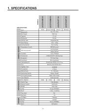
... B Automatic Icemaker The ice is produced in the icemaker and sent to become more familiar with the parts and features. Note: This guide covers several different models.The refrigerator you have purchased may not match your model. The locations of meat or fresh food. L Refrigerator Door Rack M Vegetable Drawer - 5 - PARTS IDENTIFICATION G A H B I Water Filter J Refrigerator Shelf K Snack Pan For storage of the features shown below . H Refrigerator Lamp I C J K D H L A E A M L F Use this page to the dispenser.
... B Automatic Icemaker The ice is produced in the icemaker and sent to become more familiar with the parts and features. Note: This guide covers several different models.The refrigerator you have purchased may not match your model. The locations of meat or fresh food. L Refrigerator Door Rack M Vegetable Drawer - 5 - PARTS IDENTIFICATION G A H B I Water Filter J Refrigerator Shelf K Snack Pan For storage of the features shown below . H Refrigerator Lamp I C J K D H L A E A M L F Use this page to the dispenser.
Owner's Manual
Page 7
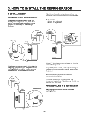
... Wrench Height Adjustment Up difference hinge pin Down If the freezer compartment door is lower than the refrigerator compartment door, make them level by inserting flat blade screwdriver into the groove of ½" (1.27 cm)). Using a 5/16" (8 mm) wrench, turn the keeper nut clockwise to lossen the keeper nut. Adjust the level when the refrigerator door is higher than the freezer door during the installation of the left leveling leg...
... Wrench Height Adjustment Up difference hinge pin Down If the freezer compartment door is lower than the refrigerator compartment door, make them level by inserting flat blade screwdriver into the groove of ½" (1.27 cm)). Using a 5/16" (8 mm) wrench, turn the keeper nut clockwise to lossen the keeper nut. Adjust the level when the refrigerator door is higher than the freezer door during the installation of the left leveling leg...
Owner's Manual
Page 8
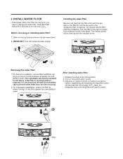
... . Open the refrigerator door and check the shelf area for the future. A Filter - 7 - The locked symbol will be retained for leaks. The substitute cap must be lined up with the indicator arrow. Before removing or installing water filter: 1. For first-time installation, remove filter substitute cap (A) by slowly turning it to the left a quarter turn clockwise to the lowest level. 2. INSTALL WATER FILTER • Filter Reset: When the Filter icon turns on household water supply. 3. Press the Filter button for...
... . Open the refrigerator door and check the shelf area for the future. A Filter - 7 - The locked symbol will be retained for leaks. The substitute cap must be lined up with the indicator arrow. Before removing or installing water filter: 1. For first-time installation, remove filter substitute cap (A) by slowly turning it to the left a quarter turn clockwise to the lowest level. 2. INSTALL WATER FILTER • Filter Reset: When the Filter icon turns on household water supply. 3. Press the Filter button for...
Owner's Manual
Page 10
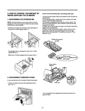
... 2) Turn on the electricity after connecting water pipe. Feeler Arm Test switch (On the lower part of icemaker) 2 1 * It is acceptable is the adjusted water level is small each time. Check the amount that goes into the ice tray. (Refer to the drawing below . 1. DISASSEMBLY ICEMAKER COVER If you need acces to avoid dropping it „ . DISASSEMBLY ICE STORAGE BIN 2) The bell rings (ding ~ dong), the ice tray rotates, and water...
... 2) Turn on the electricity after connecting water pipe. Feeler Arm Test switch (On the lower part of icemaker) 2 1 * It is acceptable is the adjusted water level is small each time. Check the amount that goes into the ice tray. (Refer to the drawing below . 1. DISASSEMBLY ICEMAKER COVER If you need acces to avoid dropping it „ . DISASSEMBLY ICE STORAGE BIN 2) The bell rings (ding ~ dong), the ice tray rotates, and water...

Owner's Manual
Page 11
... the level of water supplied is set at least three minutes before removing the main PWB cover. 310 Volts are too small, increase the water supplying time. This happens when too little water is supplied into the ice tray. 4) If the ice cubes stick together, decrease the water supplying time. Switch ON ON Switch OFF 1 2 3. Otherwise the water may spill over. Caution: When adjusting the amount of water supplied to the icemaker.
... the level of water supplied is set at least three minutes before removing the main PWB cover. 310 Volts are too small, increase the water supplying time. This happens when too little water is supplied into the ice tray. 4) If the ice cubes stick together, decrease the water supplying time. Switch ON ON Switch OFF 1 2 3. Otherwise the water may spill over. Caution: When adjusting the amount of water supplied to the icemaker.
Owner's Manual
Page 13
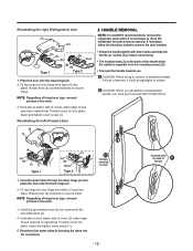
... wire opening in cabinet top. Position cover (2) into place. Reinstalling the left (Freezer) door 2. Fit top hinge (6) over hinge lever latch (5) into place. Hook tab on door switch side of cover (2) under edge of handle Position cover into the connectors. - 12 - Reconnect the water tubes by inserting the tubes into place. CAUTION: When trying to remove or install the handle if hit wit a hammer, it is necessary to move the refrigerator...
... wire opening in cabinet top. Position cover (2) into place. Reinstalling the left (Freezer) door 2. Fit top hinge (6) over hinge lever latch (5) into place. Hook tab on door switch side of cover (2) under edge of handle Position cover into the connectors. - 12 - Reconnect the water tubes by inserting the tubes into place. CAUTION: When trying to remove or install the handle if hit wit a hammer, it is necessary to move the refrigerator...
Owner's Manual
Page 24
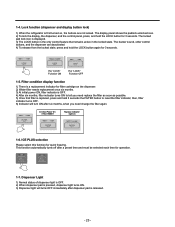
... quick freezing. Filter condition display function 1) There is a replacement indicator for 3 seconds. Dispenser Light 1) Normal status of dispenser light is OFF. 2) When dispenser pad is released. - 23 - The display panel shows the padlock unlocked icon. 2) To lock the display, the dispenser, and the control panel, press, and hold the LOCK button again for filter cartridge on the dispenser. 2) Water filter needs replacement once six months. 3) At initial power ON, filter indicator is OFF. 4) After six months, filter indicator turns ON...
... quick freezing. Filter condition display function 1) There is a replacement indicator for 3 seconds. Dispenser Light 1) Normal status of dispenser light is OFF. 2) When dispenser pad is released. - 23 - The display panel shows the padlock unlocked icon. 2) To lock the display, the dispenser, and the control panel, press, and hold the LOCK button again for filter cartridge on the dispenser. 2) Water filter needs replacement once six months. 3) At initial power ON, filter indicator is OFF. 4) After six months, filter indicator turns ON...
Owner's Manual
Page 25
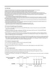
.... Control of freezing / cold storage room or Refrigerator Room are closed during the first 90 minutes of BLDC fan motor error in the freezer fan motor (refer to operate the BLDC motor, turn off and on at the lowest temperature. This function will remain activated for longer than 1 minute. 3) Closing all refrigerators doors will be ON. Door opening alarm 1) The buzzer will start seven minutes after defrosting has ended. ICE PLUS...
.... Control of freezing / cold storage room or Refrigerator Room are closed during the first 90 minutes of BLDC fan motor error in the freezer fan motor (refer to operate the BLDC motor, turn off and on at the lowest temperature. This function will remain activated for longer than 1 minute. 3) Closing all refrigerators doors will be ON. Door opening alarm 1) The buzzer will start seven minutes after defrosting has ended. ICE PLUS...
Owner's Manual
Page 27
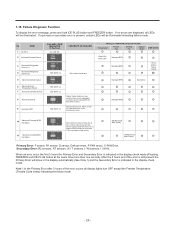
... OPEN / 15min CLOSE Standard RPM No Defrost Standard RPM 10 Abnormal Freezing BLDC Fan Motor 11 Abnormal Cooling BLDC Fan Motor Motor defect, hooked of lead wire to fan, contact of structures with fan, short or open of lead wire (there is no errors are displayed, all display lights turn OFF except the Freezer Temperature (Trouble Code Index) indicating the failure mode. - 26 - After the 3 hours and if the error is indicated in the display check mode (Pressing FREEZER and ICE PLUS button...
... OPEN / 15min CLOSE Standard RPM No Defrost Standard RPM 10 Abnormal Freezing BLDC Fan Motor 11 Abnormal Cooling BLDC Fan Motor Motor defect, hooked of lead wire to fan, contact of structures with fan, short or open of lead wire (there is no errors are displayed, all display lights turn OFF except the Freezer Temperature (Trouble Code Index) indicating the failure mode. - 26 - After the 3 hours and if the error is indicated in the display check mode (Pressing FREEZER and ICE PLUS button...
Owner's Manual
Page 29
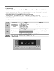
Function adjustment button is reset to keep the TEST 1. Freezer fan OFF 3. Only F & R notch are found during performance of test mode and then is not perceived during performance of test mode, release the test mode and display the failure code. 6. If Desfrost Sensor reach greater than +5°C, then Defrost Heater turn ON. If non conforming contents such as sensor failure are illuminated (first four bars from bottom...
Function adjustment button is reset to keep the TEST 1. Freezer fan OFF 3. Only F & R notch are found during performance of test mode and then is not perceived during performance of test mode, release the test mode and display the failure code. 6. If Desfrost Sensor reach greater than +5°C, then Defrost Heater turn ON. If non conforming contents such as sensor failure are illuminated (first four bars from bottom...
Owner's Manual
Page 44
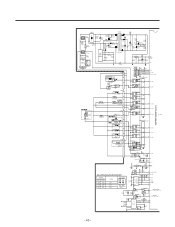
...TEST 12 P02_TXD1 11 P01_RXD1_BOOT RY(1OMIH-SS-112LM) D5 IN4004 16 1 38 P42_TXD2 RY2(OZ-SS-112L1) D6 IN4004 15 2 37 P41_RXD2 AB F-DOOR SWITCH F-LAMP TMP86FS49BFG(IC1) FUSE-MELTING DISPENSER LEVER S/W CON2 SOLENOID CUBE 9 7 DISP' HEATER OPTION 5 DEF-HEATER FUSE-M1 3 1 CON3 11 AUGER MOTOR... 3 Table 1. FIG.1 - WATER SUPPLYING TIME CONTROL(S/W 2) SWITCH LOCATION(FIG.1) S/W1 S/W2 OFF OFF ON OFF OFF ON ON ON WORK 6.5 s 5.5 s 7.5 s 8.5 s SWITCH ON ON 12 SWITCH OFF - CC8* 104 IC9 1 KIA7042 3 R83* 2 100 R15* 4.7K 8 + CE19 1uF /50V CC9* 104 RESET SW 2 2 R24* R25*...
...TEST 12 P02_TXD1 11 P01_RXD1_BOOT RY(1OMIH-SS-112LM) D5 IN4004 16 1 38 P42_TXD2 RY2(OZ-SS-112L1) D6 IN4004 15 2 37 P41_RXD2 AB F-DOOR SWITCH F-LAMP TMP86FS49BFG(IC1) FUSE-MELTING DISPENSER LEVER S/W CON2 SOLENOID CUBE 9 7 DISP' HEATER OPTION 5 DEF-HEATER FUSE-M1 3 1 CON3 11 AUGER MOTOR... 3 Table 1. FIG.1 - WATER SUPPLYING TIME CONTROL(S/W 2) SWITCH LOCATION(FIG.1) S/W1 S/W2 OFF OFF ON OFF OFF ON ON ON WORK 6.5 s 5.5 s 7.5 s 8.5 s SWITCH ON ON 12 SWITCH OFF - CC8* 104 IC9 1 KIA7042 3 R83* 2 100 R15* 4.7K 8 + CE19 1uF /50V CC9* 104 RESET SW 2 2 R24* R25*...
Owner's Manual
Page 46
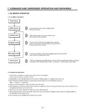
7. Dispenser Operation 1. Ice Maker operation 1-2. The function is available in models where water and ice are available without opening freezer compartment door. ª ª - 45 - ICEMAKER AND DISPENSER OPERATION AND REPAIRING 1. ICE MAKER OPERATION 1-1.
7. Dispenser Operation 1. Ice Maker operation 1-2. The function is available in models where water and ice are available without opening freezer compartment door. ª ª - 45 - ICEMAKER AND DISPENSER OPERATION AND REPAIRING 1. ICE MAKER OPERATION 1-1.

Owner's Manual
Page 59
.... Bad Stopper Not fit assembly. (inner diameter of drain. Foreign materials in the refrigerator compartment. Damping Bushing-Q. Condensation on the dispense recess. Door liner shape mismatch. Home Bar heater is open. / Foreign material clogging. Compressor sound inserted. Pipe sound. Capillary tube unattached. - 58 - CLAIMS. 6. Condensation and ice formation. Duct door heater is cut . 5) Water on the door surface. Duct door is cut . Condensation...
.... Bad Stopper Not fit assembly. (inner diameter of drain. Foreign materials in the refrigerator compartment. Damping Bushing-Q. Condensation on the dispense recess. Door liner shape mismatch. Home Bar heater is open. / Foreign material clogging. Compressor sound inserted. Pipe sound. Capillary tube unattached. - 58 - CLAIMS. 6. Condensation and ice formation. Duct door heater is cut . 5) Water on the door surface. Duct door is cut . Condensation...
Owner's Manual
Page 60
...door hinge. - 59 - No damping evaporator. CLAIMS. 7. Bad connection. - Back cover machine sound. Normal operating sound. Supporter disorted. Its own fault. - Bad connection. Fan motor sound. Burr. Tilted during expansion and contraction. 3) Bowls and bottles make contact on top shelf. 4) Refrigerator roof contact. 5) Refrigerator side contact. 6) Insufficient lubricants on the fan. - Foreign materials inside. Shroud burr contact. Narrow evaporator interval. Bad pipe caulking. 2) Freezer compartment sounds. Fan guide contact. Evaporator...
...door hinge. - 59 - No damping evaporator. CLAIMS. 7. Bad connection. - Back cover machine sound. Normal operating sound. Supporter disorted. Its own fault. - Bad connection. Fan motor sound. Burr. Tilted during expansion and contraction. 3) Bowls and bottles make contact on top shelf. 4) Refrigerator roof contact. 5) Refrigerator side contact. 6) Insufficient lubricants on the fan. - Foreign materials inside. Shroud burr contact. Narrow evaporator interval. Bad pipe caulking. 2) Freezer compartment sounds. Fan guide contact. Evaporator...

Owner's Manual
Page 62
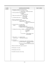
... freezer assembly. Others. Structure, appearance, and others. 1) Door foam. Noise during transportation. Fixed tape. Not tightly fastened. Malfunction. compartment is No stopper. refrigerator compartment. Deodorizer. Poor capacity. Button is open (interference by food). Food Storage. Bolt is loosened during operation. Adhesion surface. closed Interference between door liner and inner liner. Door is set atweak. Seal condition. CAUSES AND CHECK POINTS. Bigger door foam. Temperature...
... freezer assembly. Others. Structure, appearance, and others. 1) Door foam. Noise during transportation. Fixed tape. Not tightly fastened. Malfunction. compartment is No stopper. refrigerator compartment. Deodorizer. Poor capacity. Button is open (interference by food). Food Storage. Bolt is loosened during operation. Adhesion surface. closed Interference between door liner and inner liner. Door is set atweak. Seal condition. CAUSES AND CHECK POINTS. Bigger door foam. Temperature...
Owner's Manual
Page 64
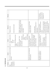
...or attach sheets. TEMPERATURE - 63 - Bad terminal contact: Check terminal visually. - Confirm icing causes and repair. Problems Causes Checks Measures Remarks High temperature in compressor compartment. - Fan shroud contact: Confirm visually. - Replace fan motor. - Reconnect and reinsert. - Faulty fan motor due to faulty - Replace door switch. - Poor cool air circulation due to faulty door switch operation. - Remove dust and contaminants compressor compartment. Lock -- 2-3. Door sag: fix door. Check the clearance between refrigerator and...
...or attach sheets. TEMPERATURE - 63 - Bad terminal contact: Check terminal visually. - Confirm icing causes and repair. Problems Causes Checks Measures Remarks High temperature in compressor compartment. - Fan shroud contact: Confirm visually. - Replace fan motor. - Reconnect and reinsert. - Faulty fan motor due to faulty - Replace door switch. - Poor cool air circulation due to faulty door switch operation. - Remove dust and contaminants compressor compartment. Lock -- 2-3. Door sag: fix door. Check the clearance between refrigerator and...
Owner's Manual
Page 84
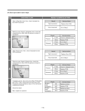
... Normal Service Action Go to Step 3 Check the Temperature and Resistance (Temperature Chart #2) Result 0 Ù Short OFF Open Other Normal Service Action Replace Defrost controller assembly, then, explain to customer. Defrost Controller 3 Assembly connector Unplug connector CON 6 from Main PCB and check between Orange to step 4. Result 0 Ù Short OFF Open Other Normal Service Action Replace Product Replace Main PCB - 83 - Plug Defrost controller assembly, then, go to Orange. 4) Abnormal Defrost Sensor Error...
... Normal Service Action Go to Step 3 Check the Temperature and Resistance (Temperature Chart #2) Result 0 Ù Short OFF Open Other Normal Service Action Replace Defrost controller assembly, then, explain to customer. Defrost Controller 3 Assembly connector Unplug connector CON 6 from Main PCB and check between Orange to step 4. Result 0 Ù Short OFF Open Other Normal Service Action Replace Product Replace Main PCB - 83 - Plug Defrost controller assembly, then, go to Orange. 4) Abnormal Defrost Sensor Error...
Owner's Manual
Page 116
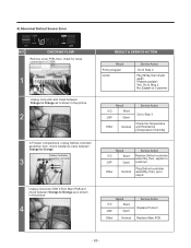
... door S/W. 21) Door open alarm never stops NO. Check the result. CHECKING FLOW Open refrigerator door, then, check manually the door S/W movement. 1 Remove cover hinge in refrigerator door, check the measurement in Door S/W DC part as is shown in the picture. 2 RESULT & SERVICE ACTION Result Tight movement Service Action Replace Door S/W Free movement Go to Step 2 Result Pressed 5 Vdc Other Released 0 Vdc Other Service Action Check in released mode Replace PCB Go to Step 3 Replace PCB Open freezer door...
... door S/W. 21) Door open alarm never stops NO. Check the result. CHECKING FLOW Open refrigerator door, then, check manually the door S/W movement. 1 Remove cover hinge in refrigerator door, check the measurement in Door S/W DC part as is shown in the picture. 2 RESULT & SERVICE ACTION Result Tight movement Service Action Replace Door S/W Free movement Go to Step 2 Result Pressed 5 Vdc Other Released 0 Vdc Other Service Action Check in released mode Replace PCB Go to Step 3 Replace PCB Open freezer door...


