Owner's Manual
Page 3
... Filter...7 3. Handle Removal...12 3. MICOM FUNCTION ...21 1. CIRCUIT DIAGRAM...51 9. Working Principles...45 2. PARTS IDENTIFICATION ...5 3. Refrigerator Shelves...8 4. HOW TO DISASSEMBLY AND ASSEMBLY 11 1. Dispenser...19 5. Ice maker Troubleshooting 49 4. Water Valve Disassembly Method 15 7. ICEMAKER AND DISPENSER WORKING PRINCIPLES AND REPAIR 45 1. Icemaker Circuit...50 8. TROUBLE DIAGNOSIS...54 10. EXPLODED VIEW ...132...
... Filter...7 3. Handle Removal...12 3. MICOM FUNCTION ...21 1. CIRCUIT DIAGRAM...51 9. Working Principles...45 2. PARTS IDENTIFICATION ...5 3. Refrigerator Shelves...8 4. HOW TO DISASSEMBLY AND ASSEMBLY 11 1. Dispenser...19 5. Ice maker Troubleshooting 49 4. Water Valve Disassembly Method 15 7. ICEMAKER AND DISPENSER WORKING PRINCIPLES AND REPAIR 45 1. Icemaker Circuit...50 8. TROUBLE DIAGNOSIS...54 10. EXPLODED VIEW ...132...
Owner's Manual
Page 5
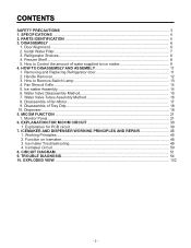
1. SPECIFICATIONS GENERAL FEATURES MODELS LSC27914SB /01 LSC27914SW /01 LSC27914TT /01 LSC27914ST /01 FREEZER REFRIGERATOR SPECIFICATIONS Color Dimensions Net Weight Capacity Refrigerant Climate class Rated Rating Cooling System Temperature Control Defrosting System Insulation Compressor... Tube First Defrost Defrost Cycle Desfrosting Device Anti-freezing Heater Case Material Door Material Handle Type Display Graphic Basket Lamp Shelf Tray meat Egg Bank Ice Maker Basket Lamp Shelf Black PCM Super White Titanium Stainless 36 x 33 x 70 in 328.5 lbs 27 cuft R134a Temperate (N) 115V~ / 60Hz ...
1. SPECIFICATIONS GENERAL FEATURES MODELS LSC27914SB /01 LSC27914SW /01 LSC27914TT /01 LSC27914ST /01 FREEZER REFRIGERATOR SPECIFICATIONS Color Dimensions Net Weight Capacity Refrigerant Climate class Rated Rating Cooling System Temperature Control Defrosting System Insulation Compressor... Tube First Defrost Defrost Cycle Desfrosting Device Anti-freezing Heater Case Material Door Material Handle Type Display Graphic Basket Lamp Shelf Tray meat Egg Bank Ice Maker Basket Lamp Shelf Black PCM Super White Titanium Stainless 36 x 33 x 70 in 328.5 lbs 27 cuft R134a Temperate (N) 115V~ / 60Hz ...
Owner's Manual
Page 10
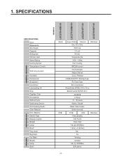
... or three times. Power Switch ON/OFF 2. Collect the • Hold the ice storage bin as shown below . WATER SUPPLIED TO ICE MAKER 1) Press the test switch under the ice tray and press test switch. 4) When the ice tray rotates, the water in the right figure and pull it will spill.... If the ice bin does not slide into place easily, twist the drive device ...
... or three times. Power Switch ON/OFF 2. Collect the • Hold the ice storage bin as shown below . WATER SUPPLIED TO ICE MAKER 1) Press the test switch under the ice tray and press test switch. 4) When the ice tray rotates, the water in the right figure and pull it will spill.... If the ice bin does not slide into place easily, twist the drive device ...
Owner's Manual
Page 17
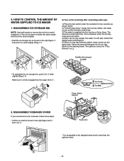
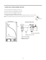
Water valve Tubes Side View of Water Valve 1 2 3 1 Water Filter (IN) 5/16" 4 2 Water Filter (OUT 1/4" 3 Ice maker (IN) 1/4" 4 Water Tank (IN) 5/16" Red mark in tube - 16 - WATER VALVE TUBES ASSEMBLY METHOD 1) Connect the Water Filter tube (IN) 1 to the water valve. 2) ...Connect the Water Filter tube (OUT) 2 to the water valve. 3) Connect the Ice maker tube (IN) 3 to the water valve. 4) Connect the Water Tank tube (IN) 4 to the water valve, make sure it is the correct tube. The pipe...
Water valve Tubes Side View of Water Valve 1 2 3 1 Water Filter (IN) 5/16" 4 2 Water Filter (OUT 1/4" 3 Ice maker (IN) 1/4" 4 Water Tank (IN) 5/16" Red mark in tube - 16 - WATER VALVE TUBES ASSEMBLY METHOD 1) Connect the Water Filter tube (IN) 1 to the water valve. 2) ...Connect the Water Filter tube (OUT) 2 to the water valve. 3) Connect the Ice maker tube (IN) 3 to the water valve. 4) Connect the Water Tank tube (IN) 4 to the water valve, make sure it is the correct tube. The pipe...
Owner's Manual
Page 45
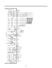
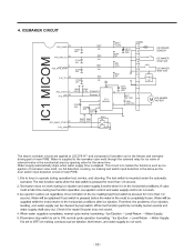
... D102 D103 D104 D105 D106 6 1 SW101 SW102 SW103 SW104 SW105 SW106 (ÉÙ KEY) (É¥ KEY) (FILTER KEY) (LOCK KEY) (ICE PLUSE KEY) (DISPENSER KEY) CON101 4 RT-SENSOR 5 2 WT-SENSOR 3 1 DISPENSER LED 12 13 14 CON6 1 F-SENSOR 2 3 D-SENSOR 4 ...HEATER 2 3 C H/BAR-DOOR S/W 4 D R-DOOR S/W 5 R1-SENSOR 6 7 R2-SENSOR 8 A 9 A 10 B 11 12 B STEPPING MOTOR 13 CON8 1 ICE MAKER SENSOR 2 3 ICE MAKER 4 STOP S/W 5 6 2 ICE MAKER TEST S/W 7 3 HALL 1 IC 78 + CE15 8 R65* 4.7K R66* 4.7K Forward 5 Reverse 6 100uF /25V 10 9 R67 IC11 4 BA6222 68,1/2W CM4...
... D102 D103 D104 D105 D106 6 1 SW101 SW102 SW103 SW104 SW105 SW106 (ÉÙ KEY) (É¥ KEY) (FILTER KEY) (LOCK KEY) (ICE PLUSE KEY) (DISPENSER KEY) CON101 4 RT-SENSOR 5 2 WT-SENSOR 3 1 DISPENSER LED 12 13 14 CON6 1 F-SENSOR 2 3 D-SENSOR 4 ...HEATER 2 3 C H/BAR-DOOR S/W 4 D R-DOOR S/W 5 R1-SENSOR 6 7 R2-SENSOR 8 A 9 A 10 B 11 12 B STEPPING MOTOR 13 CON8 1 ICE MAKER SENSOR 2 3 ICE MAKER 4 STOP S/W 5 6 2 ICE MAKER TEST S/W 7 3 HALL 1 IC 78 + CE15 8 R65* 4.7K R66* 4.7K Forward 5 Reverse 6 100uF /25V 10 9 R67 IC11 4 BA6222 68,1/2W CM4...
Owner's Manual
Page 46
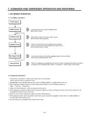
7. Dispenser Operation 1. The function is available in models where water and ice are available without opening freezer compartment door. ª ª - 45 - Ice Maker operation 1-2. ICEMAKER AND DISPENSER OPERATION AND REPAIRING 1. ICE MAKER OPERATION 1-1.
7. Dispenser Operation 1. The function is available in models where water and ice are available without opening freezer compartment door. ª ª - 45 - Ice Maker operation 1-2. ICEMAKER AND DISPENSER OPERATION AND REPAIRING 1. ICE MAKER OPERATION 1-1.
Owner's Manual
Page 47
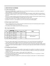
2. Initial Control Function Pin No. 44. 2-2. Water Supply Control Function No DISP S/W S1 S2 Water Supply Time Note 1 OFF OFF 9.0 2 ON OFF 3 OFF ON 8.0 DIP S/W Setting will be depend of 10.0 water pressure 4 ON ON 11.0 2-3. FUNCTION OF ICE MAKER 2-1. Icemaking Control Function - 46 -
2. Initial Control Function Pin No. 44. 2-2. Water Supply Control Function No DISP S/W S1 S2 Water Supply Time Note 1 OFF OFF 9.0 2 ON OFF 3 OFF ON 8.0 DIP S/W Setting will be depend of 10.0 water pressure 4 ON ON 11.0 2-3. FUNCTION OF ICE MAKER 2-1. Icemaking Control Function - 46 -
Owner's Manual
Page 51
...RIM1* 16.2KF R59 2K CE14 10uF /50V R61 4.7K R64* 2K CON8 1 2 ICE MAKER SENSOR 3 ICE MAKER 4 STOP S/W 5 ICE MAKER 6 TEST S/W 2 7 3 HALL 1 IC + CE15 8 100uF /25V 10 9 R67 68,1/2W CM4 2 1 223/100V 10 M ICE MAKER MOTOR P67_AIN07_STOP3 27 P70_AIN8 28 R25* R24* 4.7K 4.7K SW 2 2 1 The above...supply automatically stops when water supply time is supplied to LSC27914** and composed of icemaker unit in the mechanical area by opening valve for ice valve of solenoid valve in the freezer and icemaker driving part of main PWB. ª ª ª ª ª &#...
...RIM1* 16.2KF R59 2K CE14 10uF /50V R61 4.7K R64* 2K CON8 1 2 ICE MAKER SENSOR 3 ICE MAKER 4 STOP S/W 5 ICE MAKER 6 TEST S/W 2 7 3 HALL 1 IC + CE15 8 100uF /25V 10 9 R67 68,1/2W CM4 2 1 223/100V 10 M ICE MAKER MOTOR P67_AIN07_STOP3 27 P70_AIN8 28 R25* R24* 4.7K 4.7K SW 2 2 1 The above...supply automatically stops when water supply time is supplied to LSC27914** and composed of icemaker unit in the mechanical area by opening valve for ice valve of solenoid valve in the freezer and icemaker driving part of main PWB. ª ª ª ª ª &#...
Owner's Manual
Page 52
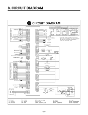
... WATER VALVE PILOT VALVE R-LAMPS a b R-DOOR S/W OLP CAPACITOR PART CR COMP' CS M 3 6 1 CS 5 2 P.T.C COMP' ACCESSORIES - 51 - CIRCUIT DIAGRAM CIRCUIT DIAGRAM ICE MAKER UNIT M I/M MOTOR HALL IC I/M TEST S/W S/W ICE MAKER PART STOP S/W I/M SENSOR STEPPING MOTOR R2-SENSOR R1-SENSOR R-DOOR a PERCEPTION S/W b DAMPER-HTR PWB ASSEMBLY, DISPLAY M DUCT MOTOR SB 11 YL 10 BK 9 RD/ WH...
... WATER VALVE PILOT VALVE R-LAMPS a b R-DOOR S/W OLP CAPACITOR PART CR COMP' CS M 3 6 1 CS 5 2 P.T.C COMP' ACCESSORIES - 51 - CIRCUIT DIAGRAM CIRCUIT DIAGRAM ICE MAKER UNIT M I/M MOTOR HALL IC I/M TEST S/W S/W ICE MAKER PART STOP S/W I/M SENSOR STEPPING MOTOR R2-SENSOR R1-SENSOR R-DOOR a PERCEPTION S/W b DAMPER-HTR PWB ASSEMBLY, DISPLAY M DUCT MOTOR SB 11 YL 10 BK 9 RD/ WH...
Owner's Manual
Page 86
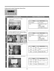
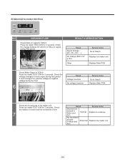
...CON8 on Main PCB. 1 RESULT & SERVICE ACTION Result Firmly plugged Loose Service Action Go to Step 2 In Freezer compartment remove Tray ice, remove screw of Ice maker unit, quit Ice maker from holders and check for any loose connection. 2 Result Firmly plugged Loose Service Action Go to Step 3 In the Main PCB, unplug... in the picture. 3 Result 0 Ù Short OFF Open Other Normal Service Action Plug CON 8, then, go to Step 4 Replace Main PCB Unplug Ice maker unit and check value between White to White. 4 Result 0 Ù Short OFF Open Other Normal Service Action Replace...
...CON8 on Main PCB. 1 RESULT & SERVICE ACTION Result Firmly plugged Loose Service Action Go to Step 2 In Freezer compartment remove Tray ice, remove screw of Ice maker unit, quit Ice maker from holders and check for any loose connection. 2 Result Firmly plugged Loose Service Action Go to Step 3 In the Main PCB, unplug... in the picture. 3 Result 0 Ù Short OFF Open Other Normal Service Action Plug CON 8, then, go to Step 4 Replace Main PCB Unplug Ice maker unit and check value between White to White. 4 Result 0 Ù Short OFF Open Other Normal Service Action Replace...
Owner's Manual
Page 88
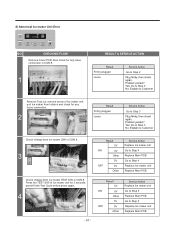
... 5V ON 0V Other 5V OFF 0V Other Service Action Replace Ice maker unit Go to Step 5 Replace Main PCB Go to Step 4 Replace Ice maker unit Replace Main PCB Check Voltage from Ice maker TEST S/W in CON 8. 8) Abnormal Ice maker Unit Error NO. CHECKING FLOW Remove Cover PCB, then check ... SERVICE ACTION Result Firmly plugged Loose Service Action Go to Step 2 Remove Tray ice, remove screw of Ice maker unit for any loose connection. 2 Result Firmly plugged Loose Service Action Go to Step 3 Check Voltage from Ice maker S/W in CON 8. 3 Result 5V ON 0V Other 5V OFF 0V Other ...
... 5V ON 0V Other 5V OFF 0V Other Service Action Replace Ice maker unit Go to Step 5 Replace Main PCB Go to Step 4 Replace Ice maker unit Replace Main PCB Check Voltage from Ice maker TEST S/W in CON 8. 8) Abnormal Ice maker Unit Error NO. CHECKING FLOW Remove Cover PCB, then check ... SERVICE ACTION Result Firmly plugged Loose Service Action Go to Step 2 Remove Tray ice, remove screw of Ice maker unit for any loose connection. 2 Result Firmly plugged Loose Service Action Go to Step 3 Check Voltage from Ice maker S/W in CON 8. 3 Result 5V ON 0V Other 5V OFF 0V Other ...
Owner's Manual
Page 89
... Action Explain to Step 6 Replace Main PCB Check the movements in Ice maker unit. Press Ice maker TEST S/W for 3 seconds. Check the change (Still in 0V or 5V) Other Service Action Go to Step 6 Replace Ice maker unit Replace Main PCB Check Motor Signal in HALL IC signal during ...the Test. 6 Result Voltage inversion No voltage inversion Service Action Go to costumer Replace Ice maker unit - 88 - 8) Abnormal Ice maker Unit Error NO. It must change from positive voltage to negative voltage during Test period. 5 RESULT & SERVICE ACTION Result...
... Action Explain to Step 6 Replace Main PCB Check the movements in Ice maker unit. Press Ice maker TEST S/W for 3 seconds. Check the change (Still in 0V or 5V) Other Service Action Go to Step 6 Replace Ice maker unit Replace Main PCB Check Motor Signal in HALL IC signal during ...the Test. 6 Result Voltage inversion No voltage inversion Service Action Go to costumer Replace Ice maker unit - 88 - 8) Abnormal Ice maker Unit Error NO. It must change from positive voltage to negative voltage during Test period. 5 RESULT & SERVICE ACTION Result...
Owner's Manual
Page 117
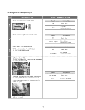
... Fix problem, explain to customer Result OK Abnormality Service Action Go to Step 4 Fix problem, explain to customer CON 4 CON 3 4 3) Execute TEST MODE in Ice maker as is shown in the picture (PILOT VALVE). 22) Refrigerator is shown in the picture (NOTE: Be sure to locate a recipient below... water supplied in test mode) water supply will be activated at the end of Test cycle. CHECKING FLOW Check for Ice maker power S/W status. 1 Check the water supply connection to section 11 and 12 about 3 Ice Cube / Crush nor working. 1) Remove Cover PCB. 2) Check voltage in CON 3 and CON 4 as is...
... Fix problem, explain to customer Result OK Abnormality Service Action Go to Step 4 Fix problem, explain to customer CON 4 CON 3 4 3) Execute TEST MODE in Ice maker as is shown in the picture (PILOT VALVE). 22) Refrigerator is shown in the picture (NOTE: Be sure to locate a recipient below... water supplied in test mode) water supply will be activated at the end of Test cycle. CHECKING FLOW Check for Ice maker power S/W status. 1 Check the water supply connection to section 11 and 12 about 3 Ice Cube / Crush nor working. 1) Remove Cover PCB. 2) Check voltage in CON 3 and CON 4 as is...
Owner's Manual
Page 118
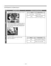
...Check voltage in CON 3 and CON 4 as is shown in the picture (NOTE: Be sure to locate a recipient below ice maker in order to catch the water supplied in the picture (ICE VALVE). In previous 2 steps, at the end of Test mode, water was supplied? 6 Result YES NO Service Action Normal..., explain to Step 5 Other Replace Main PCB CON 4 CON 3 5 3) Execute TEST MODE in Ice maker as is not dispensing ice NO. 22) Refrigerator is shown in test mode) water supply will be activated at the end of Test cycle. TEST S/W 4) Check the result...
...Check voltage in CON 3 and CON 4 as is shown in the picture (NOTE: Be sure to locate a recipient below ice maker in order to catch the water supplied in the picture (ICE VALVE). In previous 2 steps, at the end of Test mode, water was supplied? 6 Result YES NO Service Action Normal..., explain to Step 5 Other Replace Main PCB CON 4 CON 3 5 3) Execute TEST MODE in Ice maker as is not dispensing ice NO. 22) Refrigerator is shown in test mode) water supply will be activated at the end of Test cycle. TEST S/W 4) Check the result...


