Owner's Manual
Page 3
... Alignment...6 2. HOW TO DISASSEMBLY AND ASSEMBLY 11 1. Fan Shroud Grille...14 5. Dispenser...19 5. EXPLANATION FOR MICOM CIRCUIT 30 1. PARTS IDENTIFICATION ...5 3. Handle Removal...12 3. Ice maker Assembly...14 6. Water Valve Tubes Assembly Method 16 8. Icemaker Circuit...50 8. EXPLODED VIEW ...132 - 2 - ICEMAKER AND DISPENSER WORKING PRINCIPLES AND REPAIR 45 1. Freezer Shelf...8 5. Removing and Replacing...
... Alignment...6 2. HOW TO DISASSEMBLY AND ASSEMBLY 11 1. Fan Shroud Grille...14 5. Dispenser...19 5. EXPLANATION FOR MICOM CIRCUIT 30 1. PARTS IDENTIFICATION ...5 3. Handle Removal...12 3. Ice maker Assembly...14 6. Water Valve Tubes Assembly Method 16 8. Icemaker Circuit...50 8. EXPLODED VIEW ...132 - 2 - ICEMAKER AND DISPENSER WORKING PRINCIPLES AND REPAIR 45 1. Freezer Shelf...8 5. Removing and Replacing...
Owner's Manual
Page 5
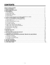
SPECIFICATIONS GENERAL FEATURES MODELS LSC27914SB /01 LSC27914SW /01 LSC27914TT /01 LSC27914ST /01 FREEZER REFRIGERATOR SPECIFICATIONS Color Dimensions Net Weight Capacity Refrigerant Climate class Rated Rating Cooling System Temperature Control Defrosting System ...Tube Type Wire Condenser Polyol Ester (POE) 310 ± 10 cc MOLECULAR SIEVE XH-7 ID Ø0.80 4 Hours 13 - 70 Hours Heater, Sheath Water Tank Heater Embo (normal) PCM VCM Vista (plastic) ICE PLUS 3full+1half Yes (2) 40W/Blue 1 (Fix) + 2 (S/Out) Yes No Twisting 4 plastic Yes (1) 40W/Blue 3EA (Wire) Stainless -...
SPECIFICATIONS GENERAL FEATURES MODELS LSC27914SB /01 LSC27914SW /01 LSC27914TT /01 LSC27914ST /01 FREEZER REFRIGERATOR SPECIFICATIONS Color Dimensions Net Weight Capacity Refrigerant Climate class Rated Rating Cooling System Temperature Control Defrosting System ...Tube Type Wire Condenser Polyol Ester (POE) 310 ± 10 cc MOLECULAR SIEVE XH-7 ID Ø0.80 4 Hours 13 - 70 Hours Heater, Sheath Water Tank Heater Embo (normal) PCM VCM Vista (plastic) ICE PLUS 3full+1half Yes (2) 40W/Blue 1 (Fix) + 2 (S/Out) Yes No Twisting 4 plastic Yes (1) 40W/Blue 3EA (Wire) Stainless -...
Owner's Manual
Page 6
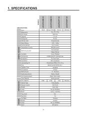
... several different models.The refrigerator you have purchased may not match your model. PARTS IDENTIFICATION G A H B I Water Filter J Refrigerator Shelf K Snack Pan For storage of dairy products such as butter and cheese. A Freezer Door Rack B Automatic Icemaker The... ice is produced in the icemaker and sent to become more familiar with the parts and features. L Refrigerator Door Rack M Vegetable Drawer - 5 - H Refrigerator Lamp I C J K...
... several different models.The refrigerator you have purchased may not match your model. PARTS IDENTIFICATION G A H B I Water Filter J Refrigerator Shelf K Snack Pan For storage of dairy products such as butter and cheese. A Freezer Door Rack B Automatic Icemaker The... ice is produced in the icemaker and sent to become more familiar with the parts and features. L Refrigerator Door Rack M Vegetable Drawer - 5 - H Refrigerator Lamp I C J K...
Owner's Manual
Page 10
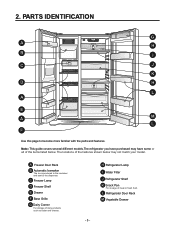
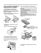
... in it will spill. Power Switch ON/OFF 2. HOW TO CONTROL THE AMOUNT OF 2) Turn on the electricity after connecting water pipe. NOTE: Use both hands to remove the ice bin to the drawing below . 1. Put a container under the icemaker for two seconds as shown in the right figure and... pull it is supplied into the auger drive … . WATER SUPPLIED TO ICE MAKER 1) Press the test switch under the ice tray and press test switch. 4) When the ice tray rotates, the water in the right figure spilled water and discard it . Feeler Arm Test switch (On the lower part of...
... in it will spill. Power Switch ON/OFF 2. HOW TO CONTROL THE AMOUNT OF 2) Turn on the electricity after connecting water pipe. NOTE: Use both hands to remove the ice bin to the drawing below . 1. Put a container under the icemaker for two seconds as shown in the right figure and... pull it is supplied into the auger drive … . WATER SUPPLIED TO ICE MAKER 1) Press the test switch under the ice tray and press test switch. 4) When the ice tray rotates, the water in the right figure spilled water and discard it . Feeler Arm Test switch (On the lower part of...

Owner's Manual
Page 11
... OFF 1 2 3. This happens when too little water is complete, check the level of water supplied depends on the setting time and water pressure (city water pressure). 3) If the ice cubes are present in the ice. - 10 - Caution: When adjusting the amount of water supplied to the icemaker. 3-2 Control the amount of water supplied, adjust step by step. Otherwise...
... OFF 1 2 3. This happens when too little water is complete, check the level of water supplied depends on the setting time and water pressure (city water pressure). 3) If the ice cubes are present in the ice. - 10 - Caution: When adjusting the amount of water supplied to the icemaker. 3-2 Control the amount of water supplied, adjust step by step. Otherwise...
Owner's Manual
Page 17
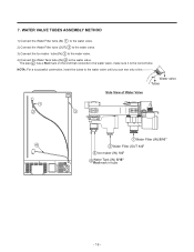
...: For a successful connection, insert the tubes to the water valve. The pipe 4 has a Red mark on the end that connects to the water valve, make sure it is the correct tube. Water valve Tubes Side View of Water Valve 1 2 3 1 Water Filter (IN) 5/16" 4 2 Water Filter (OUT 1/4" 3 Ice maker (IN) 1/4" 4 Water Tank (IN) 5/16" Red mark in tube - 16...
...: For a successful connection, insert the tubes to the water valve. The pipe 4 has a Red mark on the end that connects to the water valve, make sure it is the correct tube. Water valve Tubes Side View of Water Valve 1 2 3 1 Water Filter (IN) 5/16" 4 2 Water Filter (OUT 1/4" 3 Ice maker (IN) 1/4" 4 Water Tank (IN) 5/16" Red mark in tube - 16...
Owner's Manual
Page 22
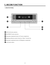
D Dispensing Selection button (Cubed Ice / Water / Crushed Ice). C Temperature adjustment button for Refrigerator compartment. F Lock function button. - 21 - MICOM FUNCTION 1. MONITOR PANEL A B F C E D A ICE PLUS function selection. B Filter RESET function selection. 5. E Temperature adjustment button for Freezer compartment.
D Dispensing Selection button (Cubed Ice / Water / Crushed Ice). C Temperature adjustment button for Refrigerator compartment. F Lock function button. - 21 - MICOM FUNCTION 1. MONITOR PANEL A B F C E D A ICE PLUS function selection. B Filter RESET function selection. 5. E Temperature adjustment button for Freezer compartment.
Owner's Manual
Page 24
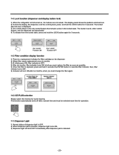
...indicator light on , the buttons are deactivated. 4) To release from the locked state, press and hold the LOCK button for 3 seconds. ICE PLUS selection Please select this function for operation. 1-7. This function automatically turns off after a preset time and must be selected each time ... hold the LOCK button again for 3 seconds. Filter condition display function 1) There is a replacement indicator for filter cartridge on the dispenser. 2) Water filter needs replacement once six months. 3) At initial power ON, filter indicator is OFF. 4) After six months, filter indicator turns ON to ...
...indicator light on , the buttons are deactivated. 4) To release from the locked state, press and hold the LOCK button for 3 seconds. ICE PLUS selection Please select this function for operation. 1-7. This function automatically turns off after a preset time and must be selected each time ... hold the LOCK button again for 3 seconds. Filter condition display function 1) There is a replacement indicator for filter cartridge on the dispenser. 2) Water filter needs replacement once six months. 3) At initial power ON, filter indicator is OFF. 4) After six months, filter indicator turns ON to ...
Owner's Manual
Page 30
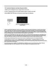
...8) Last dispensing option (CUBED ICE, CRUSHED ICE or WATER) is saved in water option, water solenoid is activated allowing water dispensing. Even after 5 seconds Duct Motor will display the last dispensing function used to dispense cubed ice, crushed ice and water. 3) Press SELECT ICE TYPE button to illuminate your desired... option to control Duct Motor and GEARED MOTOR. ICE TYPE pad has direct communication with the main PCB, Main ...
...8) Last dispensing option (CUBED ICE, CRUSHED ICE or WATER) is saved in water option, water solenoid is activated allowing water dispensing. Even after 5 seconds Duct Motor will display the last dispensing function used to dispense cubed ice, crushed ice and water. 3) Press SELECT ICE TYPE button to illuminate your desired... option to control Duct Motor and GEARED MOTOR. ICE TYPE pad has direct communication with the main PCB, Main ...
Owner's Manual
Page 33
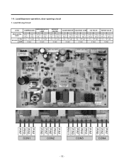
... VAC 115 ~ 127 VAC 0 VAC 0 VAC DEFROST HEATER + - CON 2 CON 2 PIN 9 PIN 3 115 ~ 127 VAC + CON 3 PIN 5 CON 4 PIN 5 115 ~ 127 VAC 0 VAC 0 VAC 0 VAC WATER VALVE + CON 3 PIN 3 CON 4 PIN 5 115 ~ 127 VAC 0 VAC PIN1 PIN3 PIN5 PIN1 PIN3 PIN5 PIN7 PIN9 PIN11 PIN1 PIN3 PIN5 PIN7 PIN9 PIN1 PIN3... - CON 3 CON 4 PIN 9 PIN 5 115 ~ 127 VAC + - CON 1 CON 1 PIN 3 PIN 7 REFRIGERATOR LAMP + - CON 2 CON 2 PIN 1 PIN 5 115 ~ 127 VAC 0 VAC AUGER MOTOR SOLENOID CUBE ICE VALVE + - 1-4. Load/dispenser operation, door opening circuit 1.
... VAC 115 ~ 127 VAC 0 VAC 0 VAC DEFROST HEATER + - CON 2 CON 2 PIN 9 PIN 3 115 ~ 127 VAC + CON 3 PIN 5 CON 4 PIN 5 115 ~ 127 VAC 0 VAC 0 VAC 0 VAC WATER VALVE + CON 3 PIN 3 CON 4 PIN 5 115 ~ 127 VAC 0 VAC PIN1 PIN3 PIN5 PIN1 PIN3 PIN5 PIN7 PIN9 PIN11 PIN1 PIN3 PIN5 PIN7 PIN9 PIN1 PIN3... - CON 3 CON 4 PIN 9 PIN 5 115 ~ 127 VAC + - CON 1 CON 1 PIN 3 PIN 7 REFRIGERATOR LAMP + - CON 2 CON 2 PIN 1 PIN 5 115 ~ 127 VAC 0 VAC AUGER MOTOR SOLENOID CUBE ICE VALVE + - 1-4. Load/dispenser operation, door opening circuit 1.
Owner's Manual
Page 44
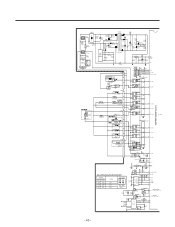
...2 B 1 78 IC16 BA6222 R86* 5 Forward 4.7K 6 Reverse 4 3 9 CC34* CC35* 223 223 R85* 4.7K CC33* 223 63 P36 64 P37 - 43 - WATER SUPPLYING TIME CONTROL(S/W 2) SWITCH LOCATION(FIG.1) S/W1 S/W2 OFF OFF ON OFF OFF ON ON ON WORK 6.5 s 5.5 s 7.5 s 8.5 s SWITCH ON ON 12 SWITCH OFF...D8 IN4004 11 3 36 P40 4 5 35 P77_AIN15 6 34 P76_AIN14 RY6(OMIH-SS-112LM) D9 IN4004 10 7 8 33 P75_AIN13 IC7* 9 KID65003AF P60_AIN00 5 ICE WATER 3 PILOT SOLENOID VALVE 1 CON4 5 3 H/BAR-HEATER OPTION 2 RY8 G5NB-1A-E 15 RY9G5NB-1A-E 14 RY10G5NB-1A-E 13 2 32 P74_AIN12 3 31 P73_AIN11 ...
...2 B 1 78 IC16 BA6222 R86* 5 Forward 4.7K 6 Reverse 4 3 9 CC34* CC35* 223 223 R85* 4.7K CC33* 223 63 P36 64 P37 - 43 - WATER SUPPLYING TIME CONTROL(S/W 2) SWITCH LOCATION(FIG.1) S/W1 S/W2 OFF OFF ON OFF OFF ON ON ON WORK 6.5 s 5.5 s 7.5 s 8.5 s SWITCH ON ON 12 SWITCH OFF...D8 IN4004 11 3 36 P40 4 5 35 P77_AIN15 6 34 P76_AIN14 RY6(OMIH-SS-112LM) D9 IN4004 10 7 8 33 P75_AIN13 IC7* 9 KID65003AF P60_AIN00 5 ICE WATER 3 PILOT SOLENOID VALVE 1 CON4 5 3 H/BAR-HEATER OPTION 2 RY8 G5NB-1A-E 15 RY9G5NB-1A-E 14 RY10G5NB-1A-E 13 2 32 P74_AIN12 3 31 P73_AIN11 ...
Owner's Manual
Page 45
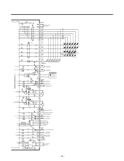
... LD129 LD130 LD131 LD128 LD132(WATER FIG.) (CUBE FIG.) LD133 LD135 LD134 R102 R103 LD136 (CRUSH R104 LD137 FIG.) 120 120 120 (ÉÙ OFF) (É¥ OFF) (LOCK KEY()FILTER KEY) LD138 LD139 LD140 LD141 LD142 (ICE/PLUS KEY) P54 56 R21... DAMPER,HEATER 2 3 C H/BAR-DOOR S/W 4 D R-DOOR S/W 5 R1-SENSOR 6 7 R2-SENSOR 8 A 9 A 10 B 11 12 B STEPPING MOTOR 13 CON8 1 ICE MAKER SENSOR 2 3 ICE MAKER 4 STOP S/W 5 6 2 ICE MAKER TEST S/W 7 3 HALL 1 IC 78 + CE15 8 R65* 4.7K R66* 4.7K Forward 5 Reverse 6 100uF /25V 10 9 R67 IC11 4 BA6222 68,1/2W CM4 CC27*...
... LD129 LD130 LD131 LD128 LD132(WATER FIG.) (CUBE FIG.) LD133 LD135 LD134 R102 R103 LD136 (CRUSH R104 LD137 FIG.) 120 120 120 (ÉÙ OFF) (É¥ OFF) (LOCK KEY()FILTER KEY) LD138 LD139 LD140 LD141 LD142 (ICE/PLUS KEY) P54 56 R21... DAMPER,HEATER 2 3 C H/BAR-DOOR S/W 4 D R-DOOR S/W 5 R1-SENSOR 6 7 R2-SENSOR 8 A 9 A 10 B 11 12 B STEPPING MOTOR 13 CON8 1 ICE MAKER SENSOR 2 3 ICE MAKER 4 STOP S/W 5 6 2 ICE MAKER TEST S/W 7 3 HALL 1 IC 78 + CE15 8 R65* 4.7K R66* 4.7K Forward 5 Reverse 6 100uF /25V 10 9 R67 IC11 4 BA6222 68,1/2W CM4 CC27*...
Owner's Manual
Page 46
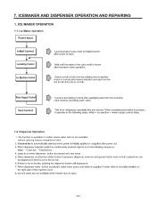
ICEMAKER AND DISPENSER OPERATION AND REPAIRING 1. The function is available in models where water and ice are available without opening freezer compartment door. ª ª - 45 - ICE MAKER OPERATION 1-1. 7. Dispenser Operation 1. Ice Maker operation 1-2.
ICEMAKER AND DISPENSER OPERATION AND REPAIRING 1. The function is available in models where water and ice are available without opening freezer compartment door. ª ª - 45 - ICE MAKER OPERATION 1-1. 7. Dispenser Operation 1. Ice Maker operation 1-2.
Owner's Manual
Page 47
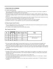
Icemaking Control Function - 46 - Water Supply Control Function No DISP S/W S1 S2 Water Supply Time Note 1 OFF OFF 9.0 2 ON OFF 3 OFF ON 8.0 DIP S/W Setting will be depend of 10.0 water pressure 4 ON ON 11.0 2-3. 2. FUNCTION OF ICE MAKER 2-1. Initial Control Function Pin No. 44. 2-2.
Icemaking Control Function - 46 - Water Supply Control Function No DISP S/W S1 S2 Water Supply Time Note 1 OFF OFF 9.0 2 ON OFF 3 OFF ON 8.0 DIP S/W Setting will be depend of 10.0 water pressure 4 ON ON 11.0 2-3. 2. FUNCTION OF ICE MAKER 2-1. Initial Control Function Pin No. 44. 2-2.
Owner's Manual
Page 51
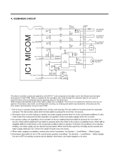
... stops when water supply time is supplied to the icemaker cube mold through the solenoid relay for ice valve of solenoid valve in the freezer and icemaker driving part of main PWB. ª ª ª ª ª ª - 50 - ICEMAKER CIRCUIT IC1 MICOM ... to realize the functions such as the door switch input detection circuit of main PWB. This circuit is the same as ice ejection of icemaker cube mold, ice full detection, leveling, ice making test switch input detection is to LSC27914** and composed of icemaker unit in the mechanical area by opening valve for...
... stops when water supply time is supplied to the icemaker cube mold through the solenoid relay for ice valve of solenoid valve in the freezer and icemaker driving part of main PWB. ª ª ª ª ª ª - 50 - ICEMAKER CIRCUIT IC1 MICOM ... to realize the functions such as the door switch input detection circuit of main PWB. This circuit is the same as ice ejection of icemaker cube mold, ice full detection, leveling, ice making test switch input detection is to LSC27914** and composed of icemaker unit in the mechanical area by opening valve for...
Owner's Manual
Page 52
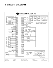
CIRCUIT DIAGRAM CIRCUIT DIAGRAM ICE MAKER UNIT M I/M MOTOR HALL IC I/M TEST S/W S/W ICE MAKER PART STOP S/W I/M SENSOR STEPPING MOTOR R2-SENSOR R1-SENSOR R-DOOR a PERCEPTION S/W b DAMPER-HTR PWB ASSEMBLY, DISPLAY M DUCT MOTOR SB 11 YL 10 BK 9 RD/ ... DIAGRAM ARE SUBJECT TO CHANGE IN DIFFERENT LOCALITIES AND MODEL TYPE. SOLENOID CUBE FUSE-M SHEATH-HTR 115V/60Hz DISPENSER LEVEL S/W FUSE-M F-DOOR S/W c d F-LAMP M AUGER MOTOR ICE VALVE WATER VALVE PILOT VALVE R-LAMPS a b R-DOOR S/W OLP CAPACITOR PART CR COMP' CS M 3 6 1 CS 5 2 P.T.C COMP' ACCESSORIES - 51 - 8.
CIRCUIT DIAGRAM CIRCUIT DIAGRAM ICE MAKER UNIT M I/M MOTOR HALL IC I/M TEST S/W S/W ICE MAKER PART STOP S/W I/M SENSOR STEPPING MOTOR R2-SENSOR R1-SENSOR R-DOOR a PERCEPTION S/W b DAMPER-HTR PWB ASSEMBLY, DISPLAY M DUCT MOTOR SB 11 YL 10 BK 9 RD/ ... DIAGRAM ARE SUBJECT TO CHANGE IN DIFFERENT LOCALITIES AND MODEL TYPE. SOLENOID CUBE FUSE-M SHEATH-HTR 115V/60Hz DISPENSER LEVEL S/W FUSE-M F-DOOR S/W c d F-LAMP M AUGER MOTOR ICE VALVE WATER VALVE PILOT VALVE R-LAMPS a b R-DOOR S/W OLP CAPACITOR PART CR COMP' CS M 3 6 1 CS 5 2 P.T.C COMP' ACCESSORIES - 51 - 8.

Owner's Manual
Page 59
Condensation and ice formation. Condensation on door. Adiabatics liquid contraction. Wing sag(lower part). Door liner shape mismatch. Broken. Tray drip. Small Capacity. Aged....HOW TO CHECK 7. Chattering sound. Damping Bushing-Q. Cormer. Bushing Too hard. Damping Bushing-S. Condensation on the dispense recess. Condensation in the compressor compartment. Defrosted water overflows. Clogged discharging hose. Sound from machine itself. Stopper. Pipe contacts each other. .- Condensation on the floor. Home Bar heater is cut . CLAIMS. ...
Condensation and ice formation. Condensation on door. Adiabatics liquid contraction. Wing sag(lower part). Door liner shape mismatch. Broken. Tray drip. Small Capacity. Aged....HOW TO CHECK 7. Chattering sound. Damping Bushing-Q. Cormer. Bushing Too hard. Damping Bushing-S. Condensation on the dispense recess. Condensation in the compressor compartment. Defrosted water overflows. Clogged discharging hose. Sound from machine itself. Stopper. Pipe contacts each other. .- Condensation on the floor. Home Bar heater is cut . CLAIMS. ...
Owner's Manual
Page 117
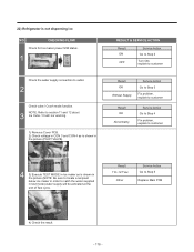
CHECKING FLOW Check for Ice maker power S/W status. 1 Check the water supply connection to Step 5 Replace Main PCB 4) Check the result. - 116 - NOTE: Refer to section 11 and 12 about 3 Ice Cube / Crush nor working. 1) Remove Cover PCB. 2) Check voltage in CON 3 and CON 4 as is shown in the picture (NOTE: Be sure to...
CHECKING FLOW Check for Ice maker power S/W status. 1 Check the water supply connection to Step 5 Replace Main PCB 4) Check the result. - 116 - NOTE: Refer to section 11 and 12 about 3 Ice Cube / Crush nor working. 1) Remove Cover PCB. 2) Check voltage in CON 3 and CON 4 as is shown in the picture (NOTE: Be sure to...
Owner's Manual
Page 118
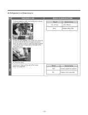
TEST S/W 4) Check the result. In previous 2 steps, at the end of Test mode, water was supplied? 6 Result YES NO Service Action Normal, explain to catch the water supplied in the picture (ICE VALVE). RESULT & SERVICE ACTION Result 110~127 Vac Service Action Go to Step 5 Other Replace Main PCB... CON 4 CON 3 5 3) Execute TEST MODE in Ice maker as is not dispensing ice NO. CHECKING FLOW 1) Check ...
TEST S/W 4) Check the result. In previous 2 steps, at the end of Test mode, water was supplied? 6 Result YES NO Service Action Normal, explain to catch the water supplied in the picture (ICE VALVE). RESULT & SERVICE ACTION Result 110~127 Vac Service Action Go to Step 5 Other Replace Main PCB... CON 4 CON 3 5 3) Execute TEST MODE in Ice maker as is not dispensing ice NO. CHECKING FLOW 1) Check ...


