
Service Manual
Page 2
... 3.2.5 MICRO SWITCH ASSEMBLY ...14 3.2.6 COIL ASSEMBLY, SOLENOID ...15 3.2.7 CONTROL PANEL ...15 3.2.8 FAN AND MOTOR...16 3.2.9 DRAIN PAN ...16 3.3 REFRIGERATING CYCLE ...17 3.3.1 CONDENSER, EVAPORATOR AND CAPILLARY TUBE 17 3.3.2 ROTARY COMPRESSOR ...17 3.4 HOW TO REPLACE REFRIGERATION SYSTEM 18 4. CIRCUIT DIAGRAM...8 3. TROUBLESHOOTING GUIDE 20 5. CONTENTS 1. PREFACE 1.1 SAFETY PRECAUTIONS ...3 1.2 FEATURES AND DIMENSIONS ...3 1.2.1 FEATURES...3 1.2.2 DIMENSIONS ...3 1.3 MODEL NAMES...
... 3.2.5 MICRO SWITCH ASSEMBLY ...14 3.2.6 COIL ASSEMBLY, SOLENOID ...15 3.2.7 CONTROL PANEL ...15 3.2.8 FAN AND MOTOR...16 3.2.9 DRAIN PAN ...16 3.3 REFRIGERATING CYCLE ...17 3.3.1 CONDENSER, EVAPORATOR AND CAPILLARY TUBE 17 3.3.2 ROTARY COMPRESSOR ...17 3.4 HOW TO REPLACE REFRIGERATION SYSTEM 18 4. CIRCUIT DIAGRAM...8 3. TROUBLESHOOTING GUIDE 20 5. CONTENTS 1. PREFACE 1.1 SAFETY PRECAUTIONS ...3 1.2 FEATURES AND DIMENSIONS ...3 1.2.1 FEATURES...3 1.2.2 DIMENSIONS ...3 1.3 MODEL NAMES...
Service Manual
Page 3
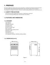
... Service Manual provides various service information, including the mechanical and electrical parts. This dehumidifier was manufactured and assembled under the strict quality control procedures. 1. The refrigerant is charged at the factory. On/Off 2Hr.
... Service Manual provides various service information, including the mechanical and electrical parts. This dehumidifier was manufactured and assembled under the strict quality control procedures. 1. The refrigerant is charged at the factory. On/Off 2Hr.
Service Manual
Page 4
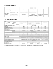
DH300EY5 DH404Y5 DH504ELY5 LD65ELY5 DH400EY5,LD40EY5 LD50ELY5 1.4 SPECIFICATIONS ITEMS MODELS POWER SUPPLY(Phase,V,Hz) INPUT(W) RUNNING CURRENT(A) ENERGY FACTOR(L/kw.h) REFRIGERANT REFRIGERANT CHARGE, oz(g) OPEN THERMISTOR CLOSE SOLENOID VALVE* COMPRESSOR MODEL No. 1.3 MODEL NAMES ...PROTECTOR CAPACITOR MOTOR ASSEMBLY,SINGLE SWITCH ASSEMBLY,MICRO OUTSIDED MENSIONS WxHxD,mm(in) NET WEIGHT,kg(lbs) DH305Y5, DH300MY5 DH300EY5 DH400MY5, LD40Y5 DH404EY5 DH400EY5, LD40EY5 DH504ELY5* LD50ELY5* LD65ELY5* 480 4.8 1.23 3.53(100) 1Ø, 115V,60Hz 58 0 560 5.7 5.4 1.36 1.75 R22 4.94(...
DH300EY5 DH404Y5 DH504ELY5 LD65ELY5 DH400EY5,LD40EY5 LD50ELY5 1.4 SPECIFICATIONS ITEMS MODELS POWER SUPPLY(Phase,V,Hz) INPUT(W) RUNNING CURRENT(A) ENERGY FACTOR(L/kw.h) REFRIGERANT REFRIGERANT CHARGE, oz(g) OPEN THERMISTOR CLOSE SOLENOID VALVE* COMPRESSOR MODEL No. 1.3 MODEL NAMES ...PROTECTOR CAPACITOR MOTOR ASSEMBLY,SINGLE SWITCH ASSEMBLY,MICRO OUTSIDED MENSIONS WxHxD,mm(in) NET WEIGHT,kg(lbs) DH305Y5, DH300MY5 DH300EY5 DH400MY5, LD40Y5 DH404EY5 DH400EY5, LD40EY5 DH504ELY5* LD50ELY5* LD65ELY5* 480 4.8 1.23 3.53(100) 1Ø, 115V,60Hz 58 0 560 5.7 5.4 1.36 1.75 R22 4.94(...
Service Manual
Page 6
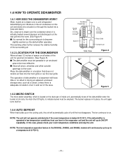
... unit, automatically shuts off until the frost disappears. The bucket replaces in an enclosed area to the room. Dry, clean air is drawn over a cold refrigerated dehumidifying coil. Moisture in the air condenses on the cooling coils, the unit will automatically cycle off the dehumidifier when the bucket is adequate circulation...
... unit, automatically shuts off until the frost disappears. The bucket replaces in an enclosed area to the room. Dry, clean air is drawn over a cold refrigerated dehumidifying coil. Moisture in the air condenses on the cooling coils, the unit will automatically cycle off the dehumidifier when the bucket is adequate circulation...

Service Manual
Page 16
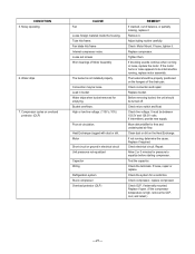
Remove 2 screws that fasten Heat Exchange. 3. 3.2.8 FAN AND MOTOR 1. Turn the nut left and full out the Fan by using a refrigerant Recovery System. 2. Remove 2 screws that fasten the H/E. 4. After purging the unit completely, unbrace the Discharge and the Suction tube connected compressor carefully. 3. Unfasten 2 screws that...the drain pan backward then take it up from the drain pan. (See Figure 24) 5. Figure 22 Figure 23 Figure 24 Figure 25 Discharge the refrigerant by hands carefully. 2. Unfasten 3 screws that secure the drain pan to base pan. (See Figure 25) 6.
Remove 2 screws that fasten Heat Exchange. 3. 3.2.8 FAN AND MOTOR 1. Turn the nut left and full out the Fan by using a refrigerant Recovery System. 2. Remove 2 screws that fasten the H/E. 4. After purging the unit completely, unbrace the Discharge and the Suction tube connected compressor carefully. 3. Unfasten 2 screws that...the drain pan backward then take it up from the drain pan. (See Figure 24) 5. Figure 22 Figure 23 Figure 24 Figure 25 Discharge the refrigerant by hands carefully. 2. Unfasten 3 screws that secure the drain pan to base pan. (See Figure 25) 6.
Service Manual
Page 17
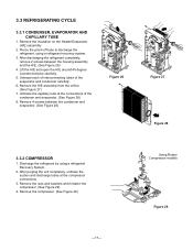
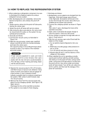
...Figure 28 3.3.2 COMPRESSOR 1. Unbraze each of interconnecting tubes of the condenser and evaporator. (See Figure 28) 8. Discharge the refrigerant by using a refrigerant recovery system. 3. Remove the compressor. (See Figure 29) Using Rotary Compressor models Figure 29 -17- Lift the H/E... and open the H/E around 45 degree counterclockwise carefully. 5. Remove the H/E assembly from the orifice. (See Figure 27) 7. 3.3 REFRIGERATING CYCLE 3.3.1 CONDENSER, EVAPORATOR AND CAPILLARY TUBE 1. Remove the insulation on the Heater/Evaporator (H/E) assembly 2. Unbraze the capillary tube at the ...
...Figure 28 3.3.2 COMPRESSOR 1. Unbraze each of interconnecting tubes of the condenser and evaporator. (See Figure 28) 8. Discharge the refrigerant by using a refrigerant recovery system. 3. Remove the compressor. (See Figure 29) Using Rotary Compressor models Figure 29 -17- Lift the H/E... and open the H/E around 45 degree counterclockwise carefully. 5. Remove the H/E assembly from the orifice. (See Figure 27) 7. 3.3 REFRIGERATING CYCLE 3.3.1 CONDENSER, EVAPORATOR AND CAPILLARY TUBE 1. Remove the insulation on the Heater/Evaporator (H/E) assembly 2. Unbraze the capillary tube at the ...
Service Manual
Page 18
...observe vacuum gauge for final charging. 7. See Figure 31B. d. After doing the above procedures, the valve must be sure to discharge the refrigerant system by means of the pinch-off the unit, allow the proper charge to set for a few minutes. This will not take it... on to the pinch-off valve B and allow pressure to rise to the Lowside. 3.4 HOW TO REPLACE THE REFRIGERATION SYSTEM 1. Open valve C. a. When replacing a refrigeration component, be closed , stop the vacuum pump. 4) Remove the hose from foaming and being drawn into the pinch-off tubes....
...observe vacuum gauge for final charging. 7. See Figure 31B. d. After doing the above procedures, the valve must be sure to discharge the refrigerant system by means of the pinch-off the unit, allow the proper charge to set for a few minutes. This will not take it... on to the pinch-off valve B and allow pressure to rise to the Lowside. 3.4 HOW TO REPLACE THE REFRIGERATION SYSTEM 1. Open valve C. a. When replacing a refrigeration component, be closed , stop the vacuum pump. 4) Remove the hose from foaming and being drawn into the pinch-off tubes....
Service Manual
Page 21
Leak in electrical circuit Unit pressures not equalized Capacitor Wiring Refrigeration system Stuck compressor Overload protector (OLP) REMEDY If cracked, out of balance, or partially missing, replace it Remove it . Heat Exchange clogged with dust or ...
Leak in electrical circuit Unit pressures not equalized Capacitor Wiring Refrigeration system Stuck compressor Overload protector (OLP) REMEDY If cracked, out of balance, or partially missing, replace it Remove it . Heat Exchange clogged with dust or ...