Owner's Manual (English)
Page 2
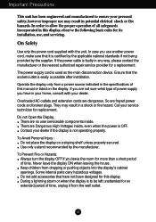
... cords are frayed power cords and broken plugs. To Avoid Personal Injury : Do not place the display on the display. Keep children from the wall outlet. A1 In order to allow the proper operation of time, unplug it is easily accessible after installation. The power supply cord is not operating properly. Do not Open the Display. There are no user serviceable components inside , even when the power...
... cords are frayed power cords and broken plugs. To Avoid Personal Injury : Do not place the display on the display. Keep children from the wall outlet. A1 In order to allow the proper operation of time, unplug it is easily accessible after installation. The power supply cord is not operating properly. Do not Open the Display. There are no user serviceable components inside , even when the power...

Owner's Manual (English)
Page 3
... fixed-resolution LCD panel. They make an ideal container in its original material. Do not rub or strike the Active Matrix LCD with general household waste. If possible, use the recommended resolution to obtain the best image quality for a long time as this product with anything to rest upon or roll over the power cord, and do not place the display where the power cord...
... fixed-resolution LCD panel. They make an ideal container in its original material. Do not rub or strike the Active Matrix LCD with general household waste. If possible, use the recommended resolution to obtain the best image quality for a long time as this product with anything to rest upon or roll over the power cord, and do not place the display where the power cord...

Owner's Manual (English)
Page 6
The Head part 3. Change your hold on the product as it follows and turn the Stand Base in the arrow direction until you hear a "click." 5. Place the monitor face down on a flat surface. Hold the product as it follows and lift up the Stand slightly. Put a cushion or soft cloth on the cushion or soft cloth. A5 The Stand base part 4. Pull out the Stand to remove. Connecting the Display To remove the Stand: 1. 2.
The Head part 3. Change your hold on the product as it follows and turn the Stand Base in the arrow direction until you hear a "click." 5. Place the monitor face down on a flat surface. Hold the product as it follows and lift up the Stand slightly. Put a cushion or soft cloth on the cushion or soft cloth. A5 The Stand base part 4. Pull out the Stand to remove. Connecting the Display To remove the Stand: 1. 2.

Owner's Manual (English)
Page 7
A6 time as it follows. 3. 4. Base are successfully separated. Pushing Latch inside, Take the stand The body of the Stand as it 2. Connecting the Display To remove the Stand Base: 1.Hold the body of the Stand and the Stand base from stand body. Press the two latches at the same follows.
A6 time as it follows. 3. 4. Base are successfully separated. Pushing Latch inside, Take the stand The body of the Stand as it 2. Connecting the Display To remove the Stand Base: 1.Hold the body of the Stand and the Stand base from stand body. Press the two latches at the same follows.
Owner's Manual (English)
Page 8
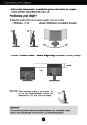
... and comfortable viewing position, the forward tilt angle of the monitor, do not put your fingers between monitor and stand bottom. Ergonomic It is not available for maximum comfort. Connecting the Display Before setting up the monitor, ensure that in various ways for all countries) 20 L1753H / L1753HR / L1953H / L1953HR Height Range : maximum 3.94 inch (100 mm) 100 mm Warning: When adjusting height of the monitor should...
... and comfortable viewing position, the forward tilt angle of the monitor, do not put your fingers between monitor and stand bottom. Ergonomic It is not available for maximum comfort. Connecting the Display Before setting up the monitor, ensure that in various ways for all countries) 20 L1753H / L1753HR / L1953H / L1953HR Height Range : maximum 3.94 inch (100 mm) 100 mm Warning: When adjusting height of the monitor should...
Owner's Manual (English)
Page 9
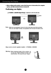
... the monitor, ensure that the power to the monitor, the computer system, and other attached devices is only for speaker models - You may hurt your fingers between monitor and stand bottom. L1753HM, L1953HM Warning: When adjusting height of the monitor, do not put your fingers. Then you use height function, the speakers will not touch the base cover. A8 Connecting the Display Before setting up the stop cover Stop cover is turned...
... the monitor, ensure that the power to the monitor, the computer system, and other attached devices is only for speaker models - You may hurt your fingers between monitor and stand bottom. L1753HM, L1953HM Warning: When adjusting height of the monitor, do not put your fingers. Then you use height function, the speakers will not touch the base cover. A8 Connecting the Display Before setting up the stop cover Stop cover is turned...
Owner's Manual (English)
Page 10
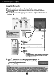
....) MAC Mac adapter For Apple Macintosh use , or wish to manually run this option initializes all the menu items except 'Language'. Connect the power cord into a proper power outlet that this function once again, push the 'AUTO/SET' button on the supplied cable to turn the power on. This is easily accessible and close to the display. 2 Power Cord Signal Cable Analog signal Digital signal D-sub DVI NOTE Varies according to change the 15 pin high density (3 row) D-sub VGA connector...
....) MAC Mac adapter For Apple Macintosh use , or wish to manually run this option initializes all the menu items except 'Language'. Connect the power cord into a proper power outlet that this function once again, push the 'AUTO/SET' button on the supplied cable to turn the power on. This is easily accessible and close to the display. 2 Power Cord Signal Cable Analog signal Digital signal D-sub DVI NOTE Varies according to change the 15 pin high density (3 row) D-sub VGA connector...

Owner's Manual (English)
Page 12
... "OSD UNLOCKED" should appear. Control Panel Functions Front Panel Controls Side Control MENU Button Function Use this button to make D-Sub or DVI connector active. This feature is D-Sub. SOURCE Hot key Use this button to enter or exit the On Screen Display. The message "OSD LOCKED" should appear. The default setting is used when two computers are connected to lock the current control settings, so that they cannot be inadvertently changed. Press and hold the MENU button for several seconds. OSD LOCKED/UNLOCKED...
... "OSD UNLOCKED" should appear. Control Panel Functions Front Panel Controls Side Control MENU Button Function Use this button to make D-Sub or DVI connector active. This feature is D-Sub. SOURCE Hot key Use this button to enter or exit the On Screen Display. The message "OSD LOCKED" should appear. The default setting is used when two computers are connected to lock the current control settings, so that they cannot be inadvertently changed. Press and hold the MENU button for several seconds. OSD LOCKED/UNLOCKED...

Owner's Manual (English)
Page 13
...the AUTO/SET button before entering the On Screen Display(OSD). The best display mode is in the On Screen Display. AUTO IMAGE ADJUSTMENT When adjusting your display image to the ideal settings for the current screen resolution size (display mode). Power Indicator This Indicator lights up blue when the display operates normally(On Mode). If the display is 17 inch monitor : 1280 x 1024 19 inch monitor : 1280 x 1024 Power Button Use this indicator color changes to amber. Control Panel Functions Control AUTO/SET Button Function Use this button to enter a selection in Sleep Mode...
...the AUTO/SET button before entering the On Screen Display(OSD). The best display mode is in the On Screen Display. AUTO IMAGE ADJUSTMENT When adjusting your display image to the ideal settings for the current screen resolution size (display mode). Power Indicator This Indicator lights up blue when the display operates normally(On Mode). If the display is 17 inch monitor : 1280 x 1024 19 inch monitor : 1280 x 1024 Power Button Use this indicator color changes to amber. Control Panel Functions Control AUTO/SET Button Function Use this button to enter a selection in Sleep Mode...
Owner's Manual (English)
Page 15
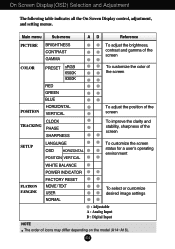
... adjust the brightness, contrast and gamma of the screen COLOR PRESET sRGB 6500K 9300K To customize the color of the screen POSITION RED GREEN BLUE HORIZONTAL VERTICAL To adjust the position of the screen CLOCK TRACKING PHASE SHARPNESS To improve the clarity and stability, sharpness of the screen SETUP LANGUAGE OSD HORIZONTAL POSITION VERTICAL To customize the screen status for a user's operating environment FLATRON F-ENGINE WHITE BALANCE POWER INDICATOR FACTORY RESET MOVIE / TEXT USER NORMAL To select or customize desired image settings : Adjustable A : Analog Input D : Digital...
... adjust the brightness, contrast and gamma of the screen COLOR PRESET sRGB 6500K 9300K To customize the color of the screen POSITION RED GREEN BLUE HORIZONTAL VERTICAL To adjust the position of the screen CLOCK TRACKING PHASE SHARPNESS To improve the clarity and stability, sharpness of the screen SETUP LANGUAGE OSD HORIZONTAL POSITION VERTICAL To customize the screen status for a user's operating environment FLATRON F-ENGINE WHITE BALANCE POWER INDICATOR FACTORY RESET MOVIE / TEXT USER NORMAL To select or customize desired image settings : Adjustable A : Analog Input D : Digital...
Owner's Manual (English)
Page 16
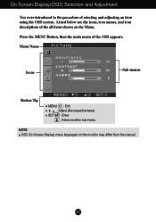
Listed below are the icons, icon names, and icon descriptions of the all items shown on the monitor may differ from the manual. Press the MENU Button, then the main menu of selecting and adjusting an item using the OSD system. Menu Name PICTURE Icons Sub-menus Button Tip MENU : Exit : Adjust (Decrease/Increase) SET : Enter : Select another sub-menu NOTE OSD (On Screen Display) menu languages on the Menu. A15 On Screen Display(OSD) Selection and Adjustment You were introduced to the procedure of the OSD appears.
Listed below are the icons, icon names, and icon descriptions of the all items shown on the monitor may differ from the manual. Press the MENU Button, then the main menu of selecting and adjusting an item using the OSD system. Menu Name PICTURE Icons Sub-menus Button Tip MENU : Exit : Adjust (Decrease/Increase) SET : Enter : Select another sub-menu NOTE OSD (On Screen Display) menu languages on the Menu. A15 On Screen Display(OSD) Selection and Adjustment You were introduced to the procedure of the OSD appears.
Owner's Manual (English)
Page 18
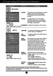
... when white and black colors are displayed. The horizontal screen size will be turned on the front side of the monitor to fit into the standard output level of the video card is an analog signal. SETUP WHITE BALANCE If the output of the video card in the screen. OSD To adjust position of the display. Press the button to video signal distortion. Activate this function to provide the optimal image. POWER INDICATOR MENU : Exit : Adjust : Adjust SET : Select another sub-menu SETUP SETUP LANGUAGE To...
... when white and black colors are displayed. The horizontal screen size will be turned on the front side of the monitor to fit into the standard output level of the video card is an analog signal. SETUP WHITE BALANCE If the output of the video card in the screen. OSD To adjust position of the display. Press the button to video signal distortion. Activate this function to provide the optimal image. POWER INDICATOR MENU : Exit : Adjust : Adjust SET : Select another sub-menu SETUP SETUP LANGUAGE To...

Owner's Manual (English)
Page 19
... text images (Word processing etc.) USER User You can save or restore the adjusted value even when using a different envir To adjust the USER sub-menu function, Press the SET Button USER BRIGHTNESS ACE 1 RCM 2 SAVE ... (Brightness): Adjusts screen brightness. ...ACE(Adaptive Clarity Enhancer): Selects the clarity mode. ...RCM(Real Color Management): Selects the color mode. 0 Not applied 1 Green enhance 2 Flesh tone 3 Color Enhance Select the SAVE sub-menu using the SET button and save the YES value using the buttons. You can manually adjust brightness...
... text images (Word processing etc.) USER User You can save or restore the adjusted value even when using a different envir To adjust the USER sub-menu function, Press the SET Button USER BRIGHTNESS ACE 1 RCM 2 SAVE ... (Brightness): Adjusts screen brightness. ...ACE(Adaptive Clarity Enhancer): Selects the clarity mode. ...RCM(Real Color Management): Selects the color mode. 0 Not applied 1 Green enhance 2 Flesh tone 3 Color Enhance Select the SAVE sub-menu using the SET button and save the YES value using the buttons. You can manually adjust brightness...
Owner's Manual (English)
Page 20
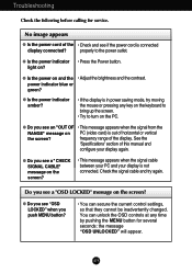
... MENU button for service. Troubleshooting Check the following before calling for several seconds: the message "OSD UNLOCKED" will appear. G Do you see if the power cord is in power saving mode, try again. A19 G Is the power indicator • Press the Power button. power indicator blue or green? G Is the power indicator amber? • If the display is connected display connected? frequency range of horizontal or vertical the screen? No image appears G Is the power cord of the • Check and see a "CHECK SIGNAL CABLE...
... MENU button for service. Troubleshooting Check the following before calling for several seconds: the message "OSD UNLOCKED" will appear. G Do you see if the power cord is in power saving mode, try again. A19 G Is the power indicator • Press the Power button. power indicator blue or green? G Is the power indicator amber? • If the display is connected display connected? frequency range of horizontal or vertical the screen? No image appears G Is the power cord of the • Check and see a "CHECK SIGNAL CABLE...

Owner's Manual (English)
Page 21
... AUTO/SET button to automatically adjust your display image to be higher than 24 bits (true color). If the results are unsatisfactory, adjust the image position using the PHASE icon in the on screen display. • Check Control Panel --> Display --> Settings and see if the frequency or the resolution were changed. If the results are unsatisfactory, decrease the horizontal bars using the H position and V position icon in the on screen display. Settings. • Check if the screen is set to interlace mode...
... AUTO/SET button to automatically adjust your display image to be higher than 24 bits (true color). If the results are unsatisfactory, adjust the image position using the PHASE icon in the on screen display. • Check Control Panel --> Display --> Settings and see if the frequency or the resolution were changed. If the results are unsatisfactory, decrease the horizontal bars using the H position and V position icon in the on screen display. Settings. • Check if the screen is set to interlace mode...
Owner's Manual (English)
Page 22
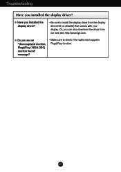
A21 Troubleshooting Have you see an "Unrecognized monitor, Plug&Play (VESA DDC) monitor found" message? • Make sure to install the display driver from our web site: http://www.lge.com. G Have you can also download the driver from the display driver CD (or diskette) that comes with your display. G Do you installed the display driver? Or, you installed the display driver? • Be sure to check if the video card supports Plug&Play function.
A21 Troubleshooting Have you see an "Unrecognized monitor, Plug&Play (VESA DDC) monitor found" message? • Make sure to install the display driver from our web site: http://www.lge.com. G Have you can also download the driver from the display driver CD (or diskette) that comes with your display. G Do you installed the display driver? Or, you installed the display driver? • Be sure to check if the video card supports Plug&Play function.

Owner's Manual (English)
Page 23
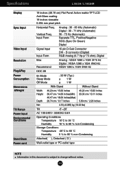
...) Separate TTL, Positive/Negative SOG (Sync On Green) Digital Signal Input Input Form 15 pin D-Sub Connector DVI - Vertical Freq. Specifications L1753H / L1753HR Display Sync Input Video Input Resolution Plug&Play Power Consumption Dimensions &Weight Tilt Range Power Input Environmental Conditions Stand Base Power cord 17 inches (43.2 cm) Flat Panel Active matrix-TFT LCD Anti-Glare coating 17 inches viewable 0.264 mm pixel pitch Horizontal Freq. D connector (Digital) RGB Analog (0.7 Vp-p/ 75 ohm), Digital Max Recommend Analog : VESA 1280 x 1024 @75 Hz Digital : VESA 1280 x 1024...
...) Separate TTL, Positive/Negative SOG (Sync On Green) Digital Signal Input Input Form 15 pin D-Sub Connector DVI - Vertical Freq. Specifications L1753H / L1753HR Display Sync Input Video Input Resolution Plug&Play Power Consumption Dimensions &Weight Tilt Range Power Input Environmental Conditions Stand Base Power cord 17 inches (43.2 cm) Flat Panel Active matrix-TFT LCD Anti-Glare coating 17 inches viewable 0.264 mm pixel pitch Horizontal Freq. D connector (Digital) RGB Analog (0.7 Vp-p/ 75 ohm), Digital Max Recommend Analog : VESA 1280 x 1024 @75 Hz Digital : VESA 1280 x 1024...

Owner's Manual (English)
Page 24
Specifications L1753HM Display 17 inches (43.2 cm) Flat Panel Active matrix-TFT LCD Anti-Glare coating 17 inches viewable 0.264 mm pixel pitch Sync Input Horizontal Freq. A23 Input Form Analog : 30 - 83 kHz (Automatic) Digital : 30 - 71 kHz (Automatic) 56 - 75 Hz (Automatic) Separate TTL, Positive/Negative SOG (Sync On Green) Digital Video Input Signal Input Input Form 15 pin D-Sub Connector DVI - Vertical Freq. D connector (Digital) RGB Analog (0.7 Vp-p/ 75 ohm), Digital Resolution Max Recommend Analog : VESA 1280 x 1024 @75 Hz Digital : VESA 1280 x 1024 @60...
Specifications L1753HM Display 17 inches (43.2 cm) Flat Panel Active matrix-TFT LCD Anti-Glare coating 17 inches viewable 0.264 mm pixel pitch Sync Input Horizontal Freq. A23 Input Form Analog : 30 - 83 kHz (Automatic) Digital : 30 - 71 kHz (Automatic) 56 - 75 Hz (Automatic) Separate TTL, Positive/Negative SOG (Sync On Green) Digital Video Input Signal Input Input Form 15 pin D-Sub Connector DVI - Vertical Freq. D connector (Digital) RGB Analog (0.7 Vp-p/ 75 ohm), Digital Resolution Max Recommend Analog : VESA 1280 x 1024 @75 Hz Digital : VESA 1280 x 1024 @60...
Owner's Manual (English)
Page 25
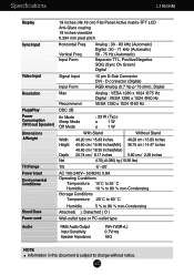
...˚C to 60 ˚C Humidity 5 % to 90 % non-Condensing Attached( ), Detached ( O ) Wall-outlet type or PC-outlet type NOTE Information in this document is subject to change without notice. Vertical Freq. Specifications L1953H / L1953HR Display Sync Input Video Input Resolution Plug&Play Power Consumption Dimensions &Weight Tilt Range Power Input Environmental Conditions Stand Base Power cord 19 inches (48.19 cm) Flat Panel Active matrix-TFT LCD Anti-Glare coating 19 inches viewable 0.294 mm pixel pitch Horizontal Freq.
...˚C to 60 ˚C Humidity 5 % to 90 % non-Condensing Attached( ), Detached ( O ) Wall-outlet type or PC-outlet type NOTE Information in this document is subject to change without notice. Vertical Freq. Specifications L1953H / L1953HR Display Sync Input Video Input Resolution Plug&Play Power Consumption Dimensions &Weight Tilt Range Power Input Environmental Conditions Stand Base Power cord 19 inches (48.19 cm) Flat Panel Active matrix-TFT LCD Anti-Glare coating 19 inches viewable 0.294 mm pixel pitch Horizontal Freq.
Owner's Manual (English)
Page 26
... L1953HM Display Sync Input 19 inches (48.19 cm) Flat Panel Active matrix-TFT LCD Anti-Glare coating 19 inches viewable 0.294 mm pixel pitch Horizontal Freq. A25 Input Form Analog : 30 - 83 kHz (Automatic) Digital : 30 - 71 kHz (Automatic) 56 - 75 Hz (Automatic) Separate TTL, Positive/Negative SOG (Sync On Green) Digital Video Input Signal Input Input Form 15 pin D-Sub Connector DVI - Vertical Freq. D connector (Digital) RGB Analog (0.7 Vp-p/ 75 ohm), Digital Resolution Plug&Play Power Consumption (Without Speaker) Dimensions &Weight Tilt Range Max Recommend Analog : VESA...
... L1953HM Display Sync Input 19 inches (48.19 cm) Flat Panel Active matrix-TFT LCD Anti-Glare coating 19 inches viewable 0.294 mm pixel pitch Horizontal Freq. A25 Input Form Analog : 30 - 83 kHz (Automatic) Digital : 30 - 71 kHz (Automatic) 56 - 75 Hz (Automatic) Separate TTL, Positive/Negative SOG (Sync On Green) Digital Video Input Signal Input Input Form 15 pin D-Sub Connector DVI - Vertical Freq. D connector (Digital) RGB Analog (0.7 Vp-p/ 75 ohm), Digital Resolution Plug&Play Power Consumption (Without Speaker) Dimensions &Weight Tilt Range Max Recommend Analog : VESA...


