
User Guide
Page 1
User's Guide L1918S LCD Computer Monitor Make sure to read the Important Precautions before using this product. Keep the User's Guide(CD) in an accessible place for support. Have the model and serial number ready when calling for furture reference.
User's Guide L1918S LCD Computer Monitor Make sure to read the Important Precautions before using this product. Keep the User's Guide(CD) in an accessible place for support. Have the model and serial number ready when calling for furture reference.

User Guide
Page 2
... your home, consult with the unit. Overloaded AC outlets and extension cords are frayed power cords and broken plugs. They may result in any way, please contact customer service or the nearest authorized repair service provider for its installation, use, and servicing. Do not Open the Display. There are Dangerous High Voltages inside . Keep children from the wall outlet. Some internal parts carry hazardous voltages.
... your home, consult with the unit. Overloaded AC outlets and extension cords are frayed power cords and broken plugs. They may result in any way, please contact customer service or the nearest authorized repair service provider for its installation, use, and servicing. Do not Open the Display. There are Dangerous High Voltages inside . Keep children from the wall outlet. Some internal parts carry hazardous voltages.

User Guide
Page 3
... electrical shock. Do not rub or strike the LCD Screen with cloth or other material. On Cleaning Unplug the display before cleaning the face of the fixed-resolution LCD panel. A2 Cover the openings with anything hard as this product must be carried out in the cabinet to allow anything to obtain the best image quality for a long time as this is characteristic...
... electrical shock. Do not rub or strike the LCD Screen with cloth or other material. On Cleaning Unplug the display before cleaning the face of the fixed-resolution LCD panel. A2 Cover the openings with anything hard as this product must be carried out in the cabinet to allow anything to obtain the best image quality for a long time as this is characteristic...

User Guide
Page 4
... power to the monitor, the computer system, and other attached devices is turned off. The product may fall and get damaged or injure your foot. REAR REAR Connecting the Display Before setting up carefully and face the front side Important Do not remove and re-install the stand frequently, it "click". 3. Connecting the stand 1. Assemble the Stand Body into the Stand Body in the picture...
... power to the monitor, the computer system, and other attached devices is turned off. The product may fall and get damaged or injure your foot. REAR REAR Connecting the Display Before setting up carefully and face the front side Important Do not remove and re-install the stand frequently, it "click". 3. Connecting the stand 1. Assemble the Stand Body into the Stand Body in the picture...

User Guide
Page 5
Place the monitor face down on a flat surface. Hold the product as it follows and lift up the Stand slightly. Pull out the Stand to remove. The Head part 3. The Stand base part 4. Connecting the Display To remove the Stand: 1. 2. Put a cushion or soft cloth on the cushion or soft cloth. A4 Change your hold on the product as it follows and turn the Stand Base in the arrow direction until you hear a "click." 5.
Place the monitor face down on a flat surface. Hold the product as it follows and lift up the Stand slightly. Pull out the Stand to remove. The Head part 3. The Stand base part 4. Connecting the Display To remove the Stand: 1. 2. Put a cushion or soft cloth on the cushion or soft cloth. A4 Change your hold on the product as it follows and turn the Stand Base in the arrow direction until you hear a "click." 5.

User Guide
Page 6
hand. Pull up the body of the Stand and the Stand holding the Stand Base with the other Base are successfully separated. The body of the Stand while 4. A5 Connecting the Display To remove the Stand Base: 1. 2. Press the two latches at the same time as it follows. 3. Hold the body of the Stand as it follows.
hand. Pull up the body of the Stand and the Stand holding the Stand Base with the other Base are successfully separated. The body of the Stand while 4. A5 Connecting the Display To remove the Stand Base: 1. 2. Press the two latches at the same time as it follows. 3. Hold the body of the Stand as it follows.

User Guide
Page 7
... the panel in order to the monitor, the computer system, and other attached devices is recommended that the power to maintain an ergonomic and comfortable viewing position, the forward tilt angle of the monitor should not exceed 5 degrees. Ergonomic It is turned off. Positioning your finger(s). You can hurt your display 1. Adjust the position of the monitor and the stand body . A6 Connecting the Display Before setting...
... the panel in order to the monitor, the computer system, and other attached devices is recommended that the power to maintain an ergonomic and comfortable viewing position, the forward tilt angle of the monitor should not exceed 5 degrees. Ergonomic It is turned off. Positioning your finger(s). You can hurt your display 1. Adjust the position of the monitor and the stand body . A6 Connecting the Display Before setting...

User Guide
Page 8
... supplied cable to a 15 pin 2 row connector. 4. This rear view represents a 2 general model; However, be aware that is turned on . Connecting the Display 1. Press button on the side switch panel to turn the power on , the 'Self Image Setting Function' is needed to manually run this function once again, push the 'AUTO/SET' button on the side panel of the rear view. your computer. 2. Connect the signal cable. NOTE The 'Self Image Setting Function' provides the user with optimal display settings...
... supplied cable to a 15 pin 2 row connector. 4. This rear view represents a 2 general model; However, be aware that is turned on . Connecting the Display 1. Press button on the side switch panel to turn the power on , the 'Self Image Setting Function' is needed to manually run this function once again, push the 'AUTO/SET' button on the side panel of the rear view. your computer. 2. Connect the signal cable. NOTE The 'Self Image Setting Function' provides the user with optimal display settings...

User Guide
Page 9
Control Panel Functions Front Panel Controls Side Control Function MENU Button Use this button to lock the current control settings, so that they cannot be inadvertently changed. Press and hold the MENU button for several seconds. The message "OSD UNLOCKED" should appear. The message "OSD LOCKED" should appear. OSD LOCKED/UNLOCKED This function allows you easily select the best desired NIGHT image condition optimized to select or adjust functions in videos or movies • PHOTO : For pictures or drawings...
Control Panel Functions Front Panel Controls Side Control Function MENU Button Use this button to lock the current control settings, so that they cannot be inadvertently changed. Press and hold the MENU button for several seconds. The message "OSD UNLOCKED" should appear. The message "OSD LOCKED" should appear. OSD LOCKED/UNLOCKED This function allows you easily select the best desired NIGHT image condition optimized to select or adjust functions in videos or movies • PHOTO : For pictures or drawings...

User Guide
Page 10
...display image to the ideal settings for the current screen resolution size (display mode). If the display is 19 inch monitor : 1280 x 1024 Power Button Use this indicator color changes to amber. The best display mode is in the On Screen Display. A9 Power Indicator This Indicator lights up green when the display operates normally(On Mode). This will automatically adjust your display settings, always press the AUTO/SET button before entering the On Screen Display(OSD). Control Panel Functions Control AUTO/SET Button Function Use this button to enter a selection in Sleep...
...display image to the ideal settings for the current screen resolution size (display mode). If the display is 19 inch monitor : 1280 x 1024 Power Button Use this indicator color changes to amber. The best display mode is in the On Screen Display. A9 Power Indicator This Indicator lights up green when the display operates normally(On Mode). This will automatically adjust your display settings, always press the AUTO/SET button before entering the On Screen Display(OSD). Control Panel Functions Control AUTO/SET Button Function Use this button to enter a selection in Sleep...

User Guide
Page 11
... the On Screen Display Control system. Use the / Buttons to adjust the item to stabilize for at least 30 minutes before making image adjustments. On Screen Display (OSD) Control Adjustment Screen Adjustment Making adjustments to the image size, position and operating parameters of the display is quick and easy with the use the o r Buttons. Exit the OSD by pressing the MENU Button. A short example is an outline of the available adjustments and selections you can make adjustments in the On Screen Display, follow...
... the On Screen Display Control system. Use the / Buttons to adjust the item to stabilize for at least 30 minutes before making image adjustments. On Screen Display (OSD) Control Adjustment Screen Adjustment Making adjustments to the image size, position and operating parameters of the display is quick and easy with the use the o r Buttons. Exit the OSD by pressing the MENU Button. A short example is an outline of the available adjustments and selections you can make adjustments in the On Screen Display, follow...

User Guide
Page 12
... Display control, adjustment, and setting menus. A11 Main menu Sub menu Reference PICTURE BRIGHTNESS CONTRAST COLOR GAMMA PRESET sRGB 6500K 9300K RED GREEN BLUE POSITION HORIZONTAL VERTICAL TRACKING CLOCK PHASE SHARPNESS SETUP LANGUAGE OSD HORIZONTAL POSITION VERTICAL To adjust the brightness, contrast and gamma of the screen To customize the color of the screen To adjust the position of the screen To improve the clarity and stability, sharpness of the screen To customize the screen status for a user's operating environment WHITE BALANCE POWER INDICATOR FACTORY RESET...
... Display control, adjustment, and setting menus. A11 Main menu Sub menu Reference PICTURE BRIGHTNESS CONTRAST COLOR GAMMA PRESET sRGB 6500K 9300K RED GREEN BLUE POSITION HORIZONTAL VERTICAL TRACKING CLOCK PHASE SHARPNESS SETUP LANGUAGE OSD HORIZONTAL POSITION VERTICAL To adjust the brightness, contrast and gamma of the screen To customize the color of the screen To adjust the position of the screen To improve the clarity and stability, sharpness of the screen To customize the screen status for a user's operating environment WHITE BALANCE POWER INDICATOR FACTORY RESET...

User Guide
Page 13
Press the MENU Button, then the main menu of selecting and adjusting an item using the OSD system. Listed below are the icons, icon names, and icon descriptions of the all items shown on the monitor may differ from the manual. A12 On Screen Display(OSD) Selection and Adjustment You were introduced to the procedure of the OSD appears. Menu Name PICTURE Icons Sub-menus Button Tip MENU : Exit : Adjust (Decrease/Increase) SET : Enter : Select another sub-menu NOTE OSD (On Screen Display) menu languages on the Menu.
Press the MENU Button, then the main menu of selecting and adjusting an item using the OSD system. Listed below are the icons, icon names, and icon descriptions of the all items shown on the monitor may differ from the manual. A12 On Screen Display(OSD) Selection and Adjustment You were introduced to the procedure of the OSD appears. Menu Name PICTURE Icons Sub-menus Button Tip MENU : Exit : Adjust (Decrease/Increase) SET : Enter : Select another sub-menu NOTE OSD (On Screen Display) menu languages on the Menu.
User Guide
Page 14
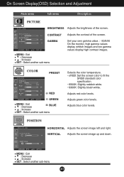
...POSITION POSITION HORIZONTAL Adjusts the screen image left and right. Adjusts red color levels. VERTICAL Adjusts the screen image up and down. On Screen Display(OSD) Selection and Adjustment Main menu Sub menu Description PICTURE PICTURE BRIGHTNESS Adjusts the brightness of the screen. MENU : Exit : Decrease : Increase SET : Select another sub-menu Selects the color temperature. • sRGB: Set the screen color to fit the SRGB standard color specification. • 6500K: Slightly reddish white. • 9300K: Slightly bluish white. COLOR COLOR PRESET RED GREEN MENU...
...POSITION POSITION HORIZONTAL Adjusts the screen image left and right. Adjusts red color levels. VERTICAL Adjusts the screen image up and down. On Screen Display(OSD) Selection and Adjustment Main menu Sub menu Description PICTURE PICTURE BRIGHTNESS Adjusts the brightness of the screen. MENU : Exit : Decrease : Increase SET : Select another sub-menu Selects the color temperature. • sRGB: Set the screen color to fit the SRGB standard color specification. • 6500K: Slightly reddish white. • 9300K: Slightly bluish white. COLOR COLOR PRESET RED GREEN MENU...

User Guide
Page 15
POWER INDICATOR MENU : Exit : Adjust : Adjust SET : Select another sub-menu SETUP SETUP SETUP LANGUAGE Chooses the language in order to video signal distortion. A14 PHASE Adjusts the focus of the video card is adjusted to ON or OFF. The horizontal screen size will also change. SET : Select another sub-menu Use this function, the signal level is different the required specifications, the color level may deteriorate due to provide the optimal image. Using this function to set the power indicator light on the...
POWER INDICATOR MENU : Exit : Adjust : Adjust SET : Select another sub-menu SETUP SETUP SETUP LANGUAGE Chooses the language in order to video signal distortion. A14 PHASE Adjusts the focus of the video card is adjusted to ON or OFF. The horizontal screen size will also change. SET : Select another sub-menu Use this function, the signal level is different the required specifications, the color level may deteriorate due to provide the optimal image. Using this function to set the power indicator light on the...

User Guide
Page 16
... if the power cord is out of horizontal or vertical the screen? light on and the • Adjust the brightness and the contrast. frequency range of this manual and configure your display is in power saving mode, try again. No image appears G Is the power cord of the • Check and see an "OUT OF • This message appears when the signal from the RANGE" message on the PC. power indicator blue or green? Troubleshooting Check the...
... if the power cord is out of horizontal or vertical the screen? light on and the • Adjust the brightness and the contrast. frequency range of this manual and configure your display is in power saving mode, try again. No image appears G Is the power cord of the • Check and see an "OUT OF • This message appears when the signal from the RANGE" message on the PC. power indicator blue or green? Troubleshooting Check the...

User Guide
Page 17
... resolution. • Make sure the power voltage is high enough, It has to be higher than 24 bits (true color). G The screen blinks. • Check if the signal cable is properly connected and use a screwdriver to fasten if necessary. • Make sure the video card is mono or abnormal. A16 Troubleshooting Display image is incorrect G Display Position is incorrect. • Press the AUTO/SET button to automatically adjust your display image to the ideal setting. G Any horizontal...
... resolution. • Make sure the power voltage is high enough, It has to be higher than 24 bits (true color). G The screen blinks. • Check if the signal cable is properly connected and use a screwdriver to fasten if necessary. • Make sure the video card is mono or abnormal. A16 Troubleshooting Display image is incorrect G Display Position is incorrect. • Press the AUTO/SET button to automatically adjust your display image to the ideal setting. G Any horizontal...

User Guide
Page 18
G Have you can also download the driver from the display driver CD (or diskette) that comes with your display. G Do you installed the display driver? Or, you installed the display driver? • Be sure to check if the video card supports Plug&Play function. Troubleshooting Have you see an "Unrecognized monitor, Plug&Play (VESA DDC) monitor found" message? • Make sure to install the display driver from our web site: http://www.lge.com. A17
G Have you can also download the driver from the display driver CD (or diskette) that comes with your display. G Do you installed the display driver? Or, you installed the display driver? • Be sure to check if the video card supports Plug&Play function. Troubleshooting Have you see an "Unrecognized monitor, Plug&Play (VESA DDC) monitor found" message? • Make sure to install the display driver from our web site: http://www.lge.com. A17

User Guide
Page 19
... Temperature -20˚C to 60 ˚C Humidity 10 % to 90 % non-Condensing Attached( ), Detached ( O ) Wall-outlet type or PC-outlet type NOTE Information in this document is subject to change without notice. Specifications Display Sync Input Video Input Resolution Plug&Play Power Consumption Dimensions &Weight Tilt Range Power Input Environmental Conditions Stand Power cord 19 inches (48 cm) Flat Panel Active matrix-TFT LCD Anti-Glare coating 19 inches viewable 0.294 mm pixel pitch Horizontal Freq. A18 Vertical Freq.
... Temperature -20˚C to 60 ˚C Humidity 10 % to 90 % non-Condensing Attached( ), Detached ( O ) Wall-outlet type or PC-outlet type NOTE Information in this document is subject to change without notice. Specifications Display Sync Input Video Input Resolution Plug&Play Power Consumption Dimensions &Weight Tilt Range Power Input Environmental Conditions Stand Power cord 19 inches (48 cm) Flat Panel Active matrix-TFT LCD Anti-Glare coating 19 inches viewable 0.294 mm pixel pitch Horizontal Freq. A18 Vertical Freq.

User Guide
Page 21
Place the monitor face down on the product as it follows and turn the Stand Base in the arrow direction until you hear a "click." 5. Change your hold on the cushion or soft cloth. Installing the Wall mount plate This monitor satisfies the specifications of the Wall mount plate or the interchange device. 1. 2. Hold the product as it follows and lift up the Stand slightly. A20 Pull out the Stand to remove. The Stand base part 4. The Head part 3. Put a cushion or soft cloth on a flat surface.
Place the monitor face down on the product as it follows and turn the Stand Base in the arrow direction until you hear a "click." 5. Change your hold on the cushion or soft cloth. Installing the Wall mount plate This monitor satisfies the specifications of the Wall mount plate or the interchange device. 1. 2. Hold the product as it follows and lift up the Stand slightly. A20 Pull out the Stand to remove. The Stand base part 4. The Head part 3. Put a cushion or soft cloth on a flat surface.


