User Guide
Page 4
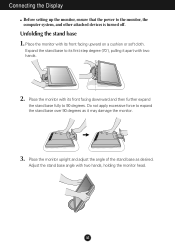
... its front facing upward on a cushion or soft cloth. Unfolding the stand base 1. Place the monitor with two hands, holding the monitor head. Expand the stand base to 90 degrees. Place the monitor upright and adjust the angle of the stand base as it apart with its front facing downward and... then further expand the stand base fully to its first step degree (70˚), pulling it may damage the monitor. 3. A3 Connecting the Display Before setting up the monitor, ensure that the power to expand the stand base over 90 degrees as desired. Do not apply excessive force to ...
... its front facing upward on a cushion or soft cloth. Unfolding the stand base 1. Place the monitor with two hands, holding the monitor head. Expand the stand base to 90 degrees. Place the monitor upright and adjust the angle of the stand base as it apart with its front facing downward and... then further expand the stand base fully to its first step degree (70˚), pulling it may damage the monitor. 3. A3 Connecting the Display Before setting up the monitor, ensure that the power to expand the stand base over 90 degrees as desired. Do not apply excessive force to ...
User Guide
Page 5
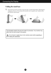
Face the front of connection. Your monitor may differ from the items shown in the picture. Do not touch or apply force to squash your hands while you fold the stand base. A4 Connecting the Display Folding the stand base 1. Be careful not to the monitor screen while expanding or folding the stand base. This illustration depicts the general model of the monitor and push the monitor backwards, following the sequence shown in the picture.
Face the front of connection. Your monitor may differ from the items shown in the picture. Do not touch or apply force to squash your hands while you fold the stand base. A4 Connecting the Display Folding the stand base 1. Be careful not to the monitor screen while expanding or folding the stand base. This illustration depicts the general model of the monitor and push the monitor backwards, following the sequence shown in the picture.
User Guide
Page 6
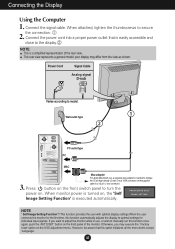
... on the OSD adjustment menu. This function provides the user with optimal display settings.When the user connects the monitor for individual input signals. Otherwise, you want to adjust the monitor while in use , a separate plug adapter is easily accessible and close to the display. When attached, tighten...For Apple Macintosh use , or wish to a 15 pin 2 row connector. A5 Connecting the Display Using the Computer 1. Connect the signal cable. When monitor power is turned on the front switch panel to model. 1 Wall-outlet type 2 PC-outlet type PC MAC 3. button on , the 'Self Image...
... on the OSD adjustment menu. This function provides the user with optimal display settings.When the user connects the monitor for individual input signals. Otherwise, you want to adjust the monitor while in use , a separate plug adapter is easily accessible and close to the display. When attached, tighten...For Apple Macintosh use , or wish to a 15 pin 2 row connector. A5 Connecting the Display Using the Computer 1. Connect the signal cable. When monitor power is turned on the front switch panel to model. 1 Wall-outlet type 2 PC-outlet type PC MAC 3. button on , the 'Self Image...
User Guide
Page 8
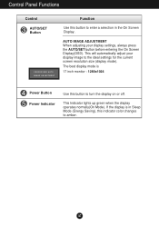
...). AUTO IMAGE ADJUSTMENT When adjusting your display image to the ideal settings for the current screen resolution size (display mode). A7 If the display is 17 inch monitor : 1280x1024 Power Button Power Indicator Use this button to enter a selection in the On Screen Display. The best display mode is in Sleep Mode...
...). AUTO IMAGE ADJUSTMENT When adjusting your display image to the ideal settings for the current screen resolution size (display mode). A7 If the display is 17 inch monitor : 1280x1024 Power Button Power Indicator Use this button to enter a selection in the On Screen Display. The best display mode is in Sleep Mode...
User Guide
Page 11
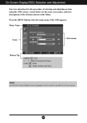
Menu Name PICTURE Icons Sub-menus Button Tip MENU : Exit - + : Adjust (Decrease/Increase) SET : Enter : Select another sub-menu NOTE OSD (On Screen Display) menu languages on the Menu. Listed below are the icons, icon names, and icon descriptions of the all items shown on the monitor may differ from the manual. A10 Press the MENU Button, then the main menu of selecting and adjusting an item using the OSD system. On Screen Display(OSD) Selection and Adjustment You were introduced to the procedure of the OSD appears.
Menu Name PICTURE Icons Sub-menus Button Tip MENU : Exit - + : Adjust (Decrease/Increase) SET : Enter : Select another sub-menu NOTE OSD (On Screen Display) menu languages on the Menu. Listed below are the icons, icon names, and icon descriptions of the all items shown on the monitor may differ from the manual. A10 Press the MENU Button, then the main menu of selecting and adjusting an item using the OSD system. On Screen Display(OSD) Selection and Adjustment You were introduced to the procedure of the OSD appears.
User Guide
Page 12
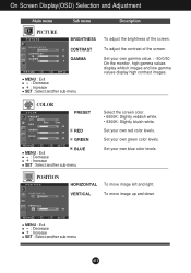
... sub-menu Select the screen color. • 6500K: Slightly reddish white. • 9300K: Slightly bluish white. Set your own gamma value. : -50/0/50 On the monitor, high gamma values display whitish images and low gamma values display high contrast images. Set your own blue color levels. To adjust the contrast of...
... sub-menu Select the screen color. • 6500K: Slightly reddish white. • 9300K: Slightly bluish white. Set your own gamma value. : -50/0/50 On the monitor, high gamma values display whitish images and low gamma values display high contrast images. Set your own blue color levels. To adjust the contrast of...
User Guide
Page 13
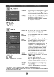
... black colors are present in which the control names are displayed. If necessary, perform the white balance function again. To adjust the focus of the monitor to reset immediately. OSD To adjust position of the OSD window POSITION on the screen background.The horizontal screen size will go off. If you...
... black colors are present in which the control names are displayed. If necessary, perform the white balance function again. To adjust the focus of the monitor to reset immediately. OSD To adjust position of the OSD window POSITION on the screen background.The horizontal screen size will go off. If you...
User Guide
Page 16
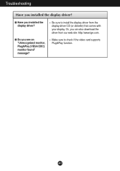
Have you can also download the driver from the display driver CD (or diskette) that comes with your display. Be sure to check if the video card supports Plug&Play function. A15 Or, you installed the display driver? Do you installed the display driver? Make sure to install the display driver from our web site: http://www.lge.com. Troubleshooting Have you see an "Unrecognized monitor, Plug&Play (VESA DDC) monitor found" message?
Have you can also download the driver from the display driver CD (or diskette) that comes with your display. Be sure to check if the video card supports Plug&Play function. A15 Or, you installed the display driver? Do you installed the display driver? Make sure to install the display driver from our web site: http://www.lge.com. Troubleshooting Have you see an "Unrecognized monitor, Plug&Play (VESA DDC) monitor found" message?
User Guide
Page 19
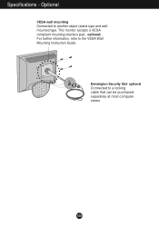
This monitor accepts a VESAcompliant mounting interface pad.- Kensington Security Slot- Optional VESA wall mounting Connected to the VESA Wall Mounting Instruction Guide. optional) For further information, refer to another object (stand type and wallmounted type. optional Connected to a locking cable that can be purchased separately at most computer stores A18 Specifications -
This monitor accepts a VESAcompliant mounting interface pad.- Kensington Security Slot- Optional VESA wall mounting Connected to the VESA Wall Mounting Instruction Guide. optional) For further information, refer to another object (stand type and wallmounted type. optional Connected to a locking cable that can be purchased separately at most computer stores A18 Specifications -
Service Manual
Page 1
Website:http://biz.LGservice.com E-mail:http://www.LGEservice.com/techsup.html COLOR MONITOR SERVICE MANUAL CHASSIS NO. : CL-82 MODEL: L1717S (L1717S-SNN.AN**EP) L1717S (L1717S-BNN.AN**EP) L1717S (L1717S-GNN.AN**EP) ( ) **Same model for Service CAUTION BEFORE SERVICING THE UNIT, READ THE SAFETY PRECAUTIONS IN THIS MANUAL. - + *To apply the MSTAR Chip.
Website:http://biz.LGservice.com E-mail:http://www.LGEservice.com/techsup.html COLOR MONITOR SERVICE MANUAL CHASSIS NO. : CL-82 MODEL: L1717S (L1717S-SNN.AN**EP) L1717S (L1717S-BNN.AN**EP) L1717S (L1717S-GNN.AN**EP) ( ) **Same model for Service CAUTION BEFORE SERVICING THE UNIT, READ THE SAFETY PRECAUTIONS IN THIS MANUAL. - + *To apply the MSTAR Chip.
Service Manual
Page 3
... hazard. • Do not modify original design without obtaining written permission from shock hazard during service operation. -3- TAKE CARE DURING HANDLING THE LCD MODULE WITH BACKLIGHT UNIT. • Must mount the module using mounting holes arranged in four corners. • Do not press on the ... void the original parts and labor guarantee. PRECAUTION WARNING FOR THE SAFETY-RELATED COMPONENT. • There are some special components used in LCD monitor that are pressed cause short and may burn or take fire. These parts are grounded through wrist band. • Do not leave ...
... hazard. • Do not modify original design without obtaining written permission from shock hazard during service operation. -3- TAKE CARE DURING HANDLING THE LCD MODULE WITH BACKLIGHT UNIT. • Must mount the module using mounting holes arranged in four corners. • Do not press on the ... void the original parts and labor guarantee. PRECAUTION WARNING FOR THE SAFETY-RELATED COMPONENT. • There are some special components used in LCD monitor that are pressed cause short and may burn or take fire. These parts are grounded through wrist band. • Do not leave ...
Service Manual
Page 11
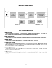
This part function is also monitor by this part. 5. This part contains of EMI components to the primary through photo transistor. - 11 - Input rectifier and filter. This part function is to ...
This part function is also monitor by this part. 5. This part contains of EMI components to the primary through photo transistor. - 11 - Input rectifier and filter. This part function is to ...
Service Manual
Page 12
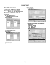
..." button c) Click " Write" button e) Click Start button. Port Setup a) Copy "UserPort.sys" file to Port Setup. f) Click Exit button. - 12 - This program is available to LCD Monitor only. 1.
..." button c) Click " Write" button e) Click Start button. Port Setup a) Copy "UserPort.sys" file to Port Setup. f) Click Exit button. - 12 - This program is available to LCD Monitor only. 1.
Service Manual
Page 13
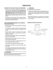
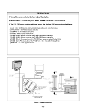
Video Signal Generator Control Line IBM Compatible PC 15 10 5 PARALLEL PORT Not used RS232C PARALLEL OFF ON 5V C F VGS A MONITOR B V-SYNC ST POWER Power inlet (required) 220 Power Select Switch (110V/220V) Power LED E ST Switch F V-Sync On/Off Switch (Switch must be ON.) A 9 11 5 6 1 6 1 ...
Video Signal Generator Control Line IBM Compatible PC 15 10 5 PARALLEL PORT Not used RS232C PARALLEL OFF ON 5V C F VGS A MONITOR B V-SYNC ST POWER Power inlet (required) 220 Power Select Switch (110V/220V) Power LED E ST Switch F V-Sync On/Off Switch (Switch must be ON.) A 9 11 5 6 1 6 1 ...


