User Guide
Page 2
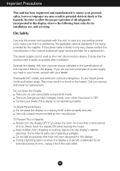
... power cable is faulty in the specifications of time, unplug it is OFF. Operate the display only from a power source indicated in any way, please contact the manufacturer or the nearest authorized repair service provider for a replacement. So are no user serviceable components inside , even when the power is certified by the applicable national standards if not being provided by the manufacturer. Keep...
... power cable is faulty in the specifications of time, unplug it is OFF. Operate the display only from a power source indicated in any way, please contact the manufacturer or the nearest authorized repair service provider for a replacement. So are no user serviceable components inside , even when the power is certified by the applicable national standards if not being provided by the manufacturer. Keep...
User Guide
Page 3
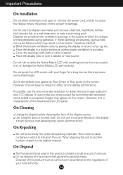
... over a radiator or heat source. Therefore, NEVER: Block the bottom ventilation slots by placing the display on the screen. On Cleaning Unplug the display before cleaning the face of the display screen. However, this is characteristic of the fixed-resolution LCD panel. Cover the openings with general household waste. If possible, use the recommended resolution to allow anything hard as this display near water such as near...
... over a radiator or heat source. Therefore, NEVER: Block the bottom ventilation slots by placing the display on the screen. On Cleaning Unplug the display before cleaning the face of the display screen. However, this is characteristic of the fixed-resolution LCD panel. Cover the openings with general household waste. If possible, use the recommended resolution to allow anything hard as this display near water such as near...
User Guide
Page 4
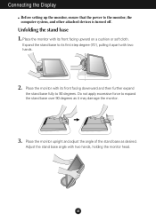
... monitor head. Adjust the stand base angle with its front facing downward and then further expand the stand base fully to expand the stand base over 90 degrees as desired. Do not apply excessive force to 90 degrees. Expand the stand base to the monitor, the computer system, and other attached devices is turned off. Place the monitor with two hands. 2. Connecting the Display Before setting...
... monitor head. Adjust the stand base angle with its front facing downward and then further expand the stand base fully to expand the stand base over 90 degrees as desired. Do not apply excessive force to 90 degrees. Expand the stand base to the monitor, the computer system, and other attached devices is turned off. Place the monitor with two hands. 2. Connecting the Display Before setting...
User Guide
Page 6
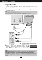
... the display. your display may execute the ' Factory reset' option on the OSD adjustment menu. When monitor power is turned on, the 'Self Image Setting Function' is easily accessible and close to manually run this function once again, push the 'AUTO/SET' button on the front switch panel to model. 1 Wall-outlet type 2 PC-outlet type PC MAC 3. However, be aware that is executed automatically. Connecting the Display Using the Computer 1. Connect the power cord into a proper power...
... the display. your display may execute the ' Factory reset' option on the OSD adjustment menu. When monitor power is turned on, the 'Self Image Setting Function' is easily accessible and close to manually run this function once again, push the 'AUTO/SET' button on the front switch panel to model. 1 Wall-outlet type 2 PC-outlet type PC MAC 3. However, be aware that is executed automatically. Connecting the Display Using the Computer 1. Connect the power cord into a proper power...
User Guide
Page 7
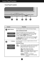
... You can unlock the OSD controls at any time by pushing the MENU button for 5 seconds. OSD LOCKED/UNLOCKED This function allows you easily select the best desired NIGHT image condition optimized to enter or exit the On Screen Display. The message "OSD UNLOCKED" should appear. The message "OSD LOCKED" should appear. - + Buttons Use these buttons to lock the current control settings, so that they cannot be inadvertently changed. Press and hold the MENU button for...
... You can unlock the OSD controls at any time by pushing the MENU button for 5 seconds. OSD LOCKED/UNLOCKED This function allows you easily select the best desired NIGHT image condition optimized to enter or exit the On Screen Display. The message "OSD UNLOCKED" should appear. The message "OSD LOCKED" should appear. - + Buttons Use these buttons to lock the current control settings, so that they cannot be inadvertently changed. Press and hold the MENU button for...
User Guide
Page 8
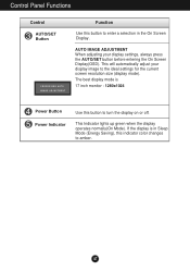
...the display is 17 inch monitor : 1280x1024 Power Button Power Indicator Use this indicator color changes to amber. This Indicator lights up green when the display operates normally(On Mode). A7 The best display mode is in the On Screen Display. This will automatically adjust your display settings, always press the AUTO/SET button before entering the On Screen Display(OSD). Control Panel Functions Control AUTO/SET Button Function Use this button to enter a selection in Sleep Mode (Energy Saving), this button to turn the display on or off. AUTO IMAGE ADJUSTMENT When adjusting...
...the display is 17 inch monitor : 1280x1024 Power Button Power Indicator Use this indicator color changes to amber. This Indicator lights up green when the display operates normally(On Mode). A7 The best display mode is in the On Screen Display. This will automatically adjust your display settings, always press the AUTO/SET button before entering the On Screen Display(OSD). Control Panel Functions Control AUTO/SET Button Function Use this button to enter a selection in Sleep Mode (Energy Saving), this button to turn the display on or off. AUTO IMAGE ADJUSTMENT When adjusting...
User Guide
Page 10
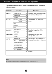
... all the On Screen Display control, adjustment, and setting menus. Main menu Sub menu PICTURE COLOR BRIGHTNESS CONTRAST GAMMA PRESET 6500K 9300K RED GREEN BLUE POSITION HORIZONTAL VERTICAL TRACKING CLOCK PHASE SETUP LANGUAGE OSD HORIZONTAL POSITION VERTICAL WHITE BALANCE POWER INDICATOR FACTORY RESET Reference To adjust the brightness, contrast and gamma of the screen To customize the color of the screen To adjust the position of the screen To improve the clarity and stability of the screen To customize the screen status for a user's operating environment : Adjustable NOTE The...
... all the On Screen Display control, adjustment, and setting menus. Main menu Sub menu PICTURE COLOR BRIGHTNESS CONTRAST GAMMA PRESET 6500K 9300K RED GREEN BLUE POSITION HORIZONTAL VERTICAL TRACKING CLOCK PHASE SETUP LANGUAGE OSD HORIZONTAL POSITION VERTICAL WHITE BALANCE POWER INDICATOR FACTORY RESET Reference To adjust the brightness, contrast and gamma of the screen To customize the color of the screen To adjust the position of the screen To improve the clarity and stability of the screen To customize the screen status for a user's operating environment : Adjustable NOTE The...
User Guide
Page 11
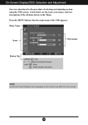
A10 Listed below are the icons, icon names, and icon descriptions of the all items shown on the monitor may differ from the manual. Press the MENU Button, then the main menu of selecting and adjusting an item using the OSD system. On Screen Display(OSD) Selection and Adjustment You were introduced to the procedure of the OSD appears. Menu Name PICTURE Icons Sub-menus Button Tip MENU : Exit - + : Adjust (Decrease/Increase) SET : Enter : Select another sub-menu NOTE OSD (On Screen Display) menu languages on the Menu.
A10 Listed below are the icons, icon names, and icon descriptions of the all items shown on the monitor may differ from the manual. Press the MENU Button, then the main menu of selecting and adjusting an item using the OSD system. On Screen Display(OSD) Selection and Adjustment You were introduced to the procedure of the OSD appears. Menu Name PICTURE Icons Sub-menus Button Tip MENU : Exit - + : Adjust (Decrease/Increase) SET : Enter : Select another sub-menu NOTE OSD (On Screen Display) menu languages on the Menu.
User Guide
Page 13
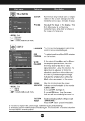
... to remove any horizontal noise and clear or sharpen the image of the display. MENU - Activate this function, the signal level is different the required specifications, the color level may deteriorate due to set the power indicator on . FACTORY RESET Restore all factory default settings except "LANGUAGE." A12 Using this function when white and black colors are present in which the control names are displayed. If you set OFF, it will be turned on...
... to remove any horizontal noise and clear or sharpen the image of the display. MENU - Activate this function, the signal level is different the required specifications, the color level may deteriorate due to set the power indicator on . FACTORY RESET Restore all factory default settings except "LANGUAGE." A12 Using this function when white and black colors are present in which the control names are displayed. If you set OFF, it will be turned on...
User Guide
Page 14
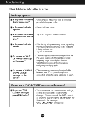
... PC (video card) is not connected. Do you see "OSD LOCKED" when you see if the power cord is in power saving mode, try again. You can secure the current control settings, so that they cannot be inadvertently changed. Adjust the brightness and the contrast. Troubleshooting Check the following before calling for 5 seconds: the message "OSD UNLOCKED" will appear. Is the power indicator light on and the power indicator blue or green? Check and see a "CHECK SIGNAL CABLE" message...
... PC (video card) is not connected. Do you see "OSD LOCKED" when you see if the power cord is in power saving mode, try again. You can secure the current control settings, so that they cannot be inadvertently changed. Adjust the brightness and the contrast. Troubleshooting Check the following before calling for 5 seconds: the message "OSD UNLOCKED" will appear. Is the power indicator light on and the power indicator blue or green? Check and see a "CHECK SIGNAL CABLE" message...

User Guide
Page 15
... on screen display. Make sure the power voltage is incorrect. If yes, readjust the video card to the ideal setting. The screen blinks. If the results are unsatisfactory, decrease the vertical bars or stripes using the PHASE icon in any image or characters are visible. Set the color setting higher than 24 bits (true color). A14 Check Control Panel --> Display --> Settings and see if the frequency or the resolution were changed. Troubleshooting Display image is incorrect Display Position is...
... on screen display. Make sure the power voltage is incorrect. If yes, readjust the video card to the ideal setting. The screen blinks. If the results are unsatisfactory, decrease the vertical bars or stripes using the PHASE icon in any image or characters are visible. Set the color setting higher than 24 bits (true color). A14 Check Control Panel --> Display --> Settings and see if the frequency or the resolution were changed. Troubleshooting Display image is incorrect Display Position is...
User Guide
Page 16
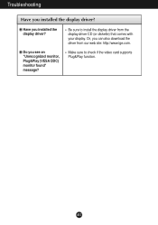
Troubleshooting Have you see an "Unrecognized monitor, Plug&Play (VESA DDC) monitor found" message? Do you installed the display driver? Or, you installed the display driver? Be sure to check if the video card supports Plug&Play function. A15 Have you can also download the driver from the display driver CD (or diskette) that comes with your display. Make sure to install the display driver from our web site: http://www.lge.com.
Troubleshooting Have you see an "Unrecognized monitor, Plug&Play (VESA DDC) monitor found" message? Do you installed the display driver? Or, you installed the display driver? Be sure to check if the video card supports Plug&Play function. A15 Have you can also download the driver from the display driver CD (or diskette) that comes with your display. Make sure to install the display driver from our web site: http://www.lge.com.

User Guide
Page 17
A16 Specifications Display Sync Input Video Input Resolution Plug&Play Power Consumption Dimensions &Weight (with tilt stand) 17 inches (43.2cm) Flat Panel Active matrix-TFT LCD Anti-Glare coating 17 inches viewable 0.264 mm pixel pitch Horizontal Freq. Input Form 30 - 83kHz (Automatic) 56 - 75Hz (Automatic) Separate TTL, Positive/Negative Composite TTL Positive/Negative SOG (Sync On Green) Signal Input Input Form 15 pin D-Sub Connector RGB Analog (0.7Vp-p/75ohm) Max Recommend VESA 1280 x 1024@75Hz VESA 1280 x 1024@60Hz DDC 2B On Mode Sleep Mode ≤...
A16 Specifications Display Sync Input Video Input Resolution Plug&Play Power Consumption Dimensions &Weight (with tilt stand) 17 inches (43.2cm) Flat Panel Active matrix-TFT LCD Anti-Glare coating 17 inches viewable 0.264 mm pixel pitch Horizontal Freq. Input Form 30 - 83kHz (Automatic) 56 - 75Hz (Automatic) Separate TTL, Positive/Negative Composite TTL Positive/Negative SOG (Sync On Green) Signal Input Input Form 15 pin D-Sub Connector RGB Analog (0.7Vp-p/75ohm) Max Recommend VESA 1280 x 1024@75Hz VESA 1280 x 1024@60Hz DDC 2B On Mode Sleep Mode ≤...
Service Manual
Page 2
... BLOCK DIAGRAM 10 ADJUSTMENT 12 SERVICE OSD 13 TROUBLESHOOTING GUIDE 14 WIRING DIAGRAM 18 EXPLODED VIEW 19 REPLACEMENT PARTS LIST 21 SCHEMATIC DIAGRAM 23 SPECIFICATIONS 1. OPTICAL CHARACTERISTICS 2-1. Viewing Angle by Contrast Ratio ≥ 10 Left : -60° min., -70°(Typ) Right : +60° min., +70°(Typ) Top : +60° min., +75°(Typ) Bottom : -50° min., -65°(Typ) 4. Power Consumption MODE H/V SYNC VIDEO POWER CONSUMPTION LED COLOR POWER ON...
... BLOCK DIAGRAM 10 ADJUSTMENT 12 SERVICE OSD 13 TROUBLESHOOTING GUIDE 14 WIRING DIAGRAM 18 EXPLODED VIEW 19 REPLACEMENT PARTS LIST 21 SCHEMATIC DIAGRAM 23 SPECIFICATIONS 1. OPTICAL CHARACTERISTICS 2-1. Viewing Angle by Contrast Ratio ≥ 10 Left : -60° min., -70°(Typ) Right : +60° min., +70°(Typ) Top : +60° min., +75°(Typ) Bottom : -50° min., -65°(Typ) 4. Power Consumption MODE H/V SYNC VIDEO POWER CONSUMPTION LED COLOR POWER ON...
Service Manual
Page 3
... Make certain that treatment person's body are grounded through wrist band. • Do not leave the module in high temperature and in LCD monitor that these critical parts should be exposed to the screen. • Do not scratch or press on the schematic diagram and the replacement parts ...LCD MODULE WITH BACKLIGHT UNIT. • Must mount the module using mounting holes arranged in four corners. • Do not press on the panel, edge of the inverter circuit. It is essential that are important for a long time. • The module not be replaced with care wires or connectors...
... Make certain that treatment person's body are grounded through wrist band. • Do not leave the module in high temperature and in LCD monitor that these critical parts should be exposed to the screen. • Do not scratch or press on the schematic diagram and the replacement parts ...LCD MODULE WITH BACKLIGHT UNIT. • Must mount the module using mounting holes arranged in four corners. • Do not press on the panel, edge of the inverter circuit. It is essential that are important for a long time. • The module not be replaced with care wires or connectors...
Service Manual
Page 4
... immediately before connecting the test receiver positive lead. Remember: Safety First. Always unplug the receiver AC power cord from the leads of electrolytic capacitors may result in this service manual. Disconnecting or reconnecting any plug/socket B+ voltage interlocks with which should be damaged easily by static electricity. CAUTION: A wrong part substitution or incorrect polarity installation of a replacement ES device, touch the...
... immediately before connecting the test receiver positive lead. Remember: Safety First. Always unplug the receiver AC power cord from the leads of electrolytic capacitors may result in this service manual. Disconnecting or reconnecting any plug/socket B+ voltage interlocks with which should be damaged easily by static electricity. CAUTION: A wrong part substitution or incorrect polarity installation of a replacement ES device, touch the...

Service Manual
Page 10
... 25MHz to 135MHz. The Scaler gets the video signal converted analog to digital, interpolates input to 1280 X 1024 resolution signal and outputs 8-bit R, G, B signal to AC 700Vrms and operates back-light lamps of the one 3.3V, and one 1.8V regulators to the digital video signal using a pixel clock. This part consists of module. 3. MICOM Part. Converted power is provided for LCD panel and 5V for IC in EEPROM. - 10...
... 25MHz to 135MHz. The Scaler gets the video signal converted analog to digital, interpolates input to 1280 X 1024 resolution signal and outputs 8-bit R, G, B signal to AC 700Vrms and operates back-light lamps of the one 3.3V, and one 1.8V regulators to the digital video signal using a pixel clock. This part consists of module. 3. MICOM Part. Converted power is provided for LCD panel and 5V for IC in EEPROM. - 10...
Service Manual
Page 12
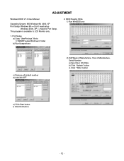
... Windows 98, 2000, XP Port Setup: Windows 98 => Don't need setup Windows 2000, XP => Need to "c:\WINNT\system32\drivers" folder b) Run Userport.exe 2. Port Setup a) Copy "UserPort.sys" file to Port Setup. f) Click Exit button. - 12 - EDID Read & Write 1) Run WinEDID.exe c) Remove all default number d) Add 300-3FF 2) Edit Week of Manufacture, Year of Manufacture, Serial Number a) Input User Info Data b) Click "Update" button c) Click " Write" button e) Click Start button. This program is available to LCD Monitor...
... Windows 98, 2000, XP Port Setup: Windows 98 => Don't need setup Windows 2000, XP => Need to "c:\WINNT\system32\drivers" folder b) Run Userport.exe 2. Port Setup a) Copy "UserPort.sys" file to Port Setup. f) Click Exit button. - 12 - EDID Read & Write 1) Run WinEDID.exe c) Remove all default number d) Add 300-3FF 2) Edit Week of Manufacture, Year of Manufacture, Serial Number a) Input User Info Data b) Click "Update" button c) Click " Write" button e) Click Start button. This program is available to LCD Monitor...
Service Manual
Page 13
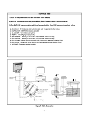
... R/G/B-Offset value manually.(Analog Only) h) R/G/B-Gain : Allows you to set the R/G/B-9300K value manually. Cable Connection - 13 - e) R/G/B-9300K : Allows you to set the R/G/B-Gain value manually.(Analog Only) i) MODULE : To select applied module. Video Signal Generator Control Line IBM Compatible PC 15 10 5 PARALLEL PORT Not used RS232C PARALLEL OFF ON 5V C F VGS A MONITOR B V-SYNC ST POWER Power inlet (required) 220 Power Select Switch (110V/220V) Power LED E ST Switch F V-Sync On/Off Switch (Switch must be...
... R/G/B-Offset value manually.(Analog Only) h) R/G/B-Gain : Allows you to set the R/G/B-9300K value manually. Cable Connection - 13 - e) R/G/B-9300K : Allows you to set the R/G/B-Gain value manually.(Analog Only) i) MODULE : To select applied module. Video Signal Generator Control Line IBM Compatible PC 15 10 5 PARALLEL PORT Not used RS232C PARALLEL OFF ON 5V C F VGS A MONITOR B V-SYNC ST POWER Power inlet (required) 220 Power Select Switch (110V/220V) Power LED E ST Switch F V-Sync On/Off Switch (Switch must be...
Service Manual
Page 16
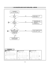
YES U201 1 PIN96, 97 NO OSCILLATE AS 12MHZ? TROUBLE IN U201 U501 PIN43 IS 48KHz H-SYNC? 2 PIN44 IS 60Hz V-SYNC? NO RASTER (OSD IS NOT DISPLAYED) - CHECK PIN122, 123 SOLDERING CONDITION 2. AT MODE 12? YES CHECK U801 (17", 19") CHECK U803 (15") 1. CHECK X501 3. MSTAR NO RASTER (OSD IS NOT DISPLAYED) U201 NO PIN 18, 90 3.3V? 3. NO IS PULSE APPEARED AT SIGNAL PINS? YES TROUBLE IN CABLE OR LCD MODULE CHECK CONNECTION LINE FROM D-SUB TO U501 Waveforms 1 U201-#96, 97 2 U501-#43 H-SYNC 2 U501-#44 V-SYNC - 16 -
YES U201 1 PIN96, 97 NO OSCILLATE AS 12MHZ? TROUBLE IN U201 U501 PIN43 IS 48KHz H-SYNC? 2 PIN44 IS 60Hz V-SYNC? NO RASTER (OSD IS NOT DISPLAYED) - CHECK PIN122, 123 SOLDERING CONDITION 2. AT MODE 12? YES CHECK U801 (17", 19") CHECK U803 (15") 1. CHECK X501 3. MSTAR NO RASTER (OSD IS NOT DISPLAYED) U201 NO PIN 18, 90 3.3V? 3. NO IS PULSE APPEARED AT SIGNAL PINS? YES TROUBLE IN CABLE OR LCD MODULE CHECK CONNECTION LINE FROM D-SUB TO U501 Waveforms 1 U201-#96, 97 2 U501-#43 H-SYNC 2 U501-#44 V-SYNC - 16 -


