User Guide
Page 16
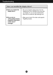
Or, you installed the display driver? Make sure to install the display driver from our web site: http://www.lge.com. Have you see an "Unrecognized monitor, Plug&Play (VESA DDC) monitor found" message? Do you installed the display driver? A15 Troubleshooting Have you can also download the driver from the display driver CD (or diskette) that comes with your display. Be sure to check if the video card supports Plug&Play function.
Or, you installed the display driver? Make sure to install the display driver from our web site: http://www.lge.com. Have you see an "Unrecognized monitor, Plug&Play (VESA DDC) monitor found" message? Do you installed the display driver? A15 Troubleshooting Have you can also download the driver from the display driver CD (or diskette) that comes with your display. Be sure to check if the video card supports Plug&Play function.
Service Manual
Page 11
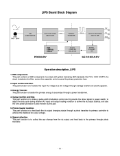
... 1. Input rectifier and filter. Output rectifier and filter. This part function is to make a pulse width modulation control and to provide the driver signal to power switch, to adjust the duty cycle during different AC input and output loading condition to achive the dc output stablize, and ... any change from the dc output and feed back to the primary through a bridge rectifier and a bulk capacitor. 3. This part function is also monitor by this part. 5. Energy Transfer. Photo-Coupler isolation. This part function is for transfer the input AC voltage to feed back the dc output...
... 1. Input rectifier and filter. Output rectifier and filter. This part function is to make a pulse width modulation control and to provide the driver signal to power switch, to adjust the duty cycle during different AC input and output loading condition to achive the dc output stablize, and ... any change from the dc output and feed back to the primary through a bridge rectifier and a bulk capacitor. 3. This part function is also monitor by this part. 5. Energy Transfer. Photo-Coupler isolation. This part function is for transfer the input AC voltage to feed back the dc output...
Service Manual
Page 12
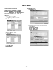
... EDID V1.0 User Manual Operating System: MS Windows 98, 2000, XP Port Setup: Windows 98 => Don't need setup Windows 2000, XP => Need to "c:\WINNT\system32\drivers" folder b) Run Userport.exe 2. f) Click Exit button. - 12 - EDID Read & Write 1) Run WinEDID.exe c) Remove all default number d) Add 300-3FF 2) Edit Week of Manufacture... Info Data b) Click "Update" button c) Click " Write" button e) Click Start button. Port Setup a) Copy "UserPort.sys" file to Port Setup. This program is available to LCD Monitor only. 1.
... EDID V1.0 User Manual Operating System: MS Windows 98, 2000, XP Port Setup: Windows 98 => Don't need setup Windows 2000, XP => Need to "c:\WINNT\system32\drivers" folder b) Run Userport.exe 2. f) Click Exit button. - 12 - EDID Read & Write 1) Run WinEDID.exe c) Remove all default number d) Add 300-3FF 2) Edit Week of Manufacture... Info Data b) Click "Update" button c) Click " Write" button e) Click Start button. Port Setup a) Copy "UserPort.sys" file to Port Setup. This program is available to LCD Monitor only. 1.

