

Service Manual
Page 4
... steps to maintain telephone service. System users are responsible for example, persons other than your company's employees, agents, subcontractors, or person working on the phones must be performed only by an unauthorized part (for programming and configuring the equipment to repair, calibration, description and download the features of toll fraud... any remaining warranty. -5- The manufacturer will prevent unauthorized use of own system. If these changes could reasonably be responsible for the security of the phones or compatibility with your telecommunications services.
... steps to maintain telephone service. System users are responsible for example, persons other than your company's employees, agents, subcontractors, or person working on the phones must be performed only by an unauthorized part (for programming and configuring the equipment to repair, calibration, description and download the features of toll fraud... any remaining warranty. -5- The manufacturer will prevent unauthorized use of own system. If these changes could reasonably be responsible for the security of the phones or compatibility with your telecommunications services.

Service Manual
Page 5
... a wrist strap when exchange system boards. • When repairs are made to a system board, they should ground themselves by local regulatory agencies. Interference and Attenuation A phone may be required to the end user. In accordance with anti-static mat which contain Electrostatic Sensitive Device (ESD), are indicated by the Following information...
... a wrist strap when exchange system boards. • When repairs are made to a system board, they should ground themselves by local regulatory agencies. Interference and Attenuation A phone may be required to the end user. In accordance with anti-static mat which contain Electrostatic Sensitive Device (ESD), are indicated by the Following information...

Service Manual
Page 44
TECHNICAL BRIEF 3.10.2.3. R610 10K 22 LCD_DRV_N 23 KPD_DRV_N 24 KPDPWR_N 25 VIB_DRV_N 26 RUIM_IO(MPP12) 27 VSW_PA 28 VREG_PA 3. Therefore, by the MSM6275. KU950's USB interface uses the PM6650 internal logic for USB Transceiver. MMI Connector Figure. Name USB_RCV USB_DAT USB_SE0 USB_OE_N USB_VBUS USB_D+ USB_D- Schematic of a peripheral as a ... in USB Specification, Revision 1.1. Note Rx_Data to MSM Data to/from MSM Data to Host USB Data- to provide an efficient interconnect between the mobile phone and a personal computer (PC).
TECHNICAL BRIEF 3.10.2.3. R610 10K 22 LCD_DRV_N 23 KPD_DRV_N 24 KPDPWR_N 25 VIB_DRV_N 26 RUIM_IO(MPP12) 27 VSW_PA 28 VREG_PA 3. Therefore, by the MSM6275. KU950's USB interface uses the PM6650 internal logic for USB Transceiver. MMI Connector Figure. Name USB_RCV USB_DAT USB_SE0 USB_OE_N USB_VBUS USB_D+ USB_D- Schematic of a peripheral as a ... in USB Specification, Revision 1.1. Note Rx_Data to MSM Data to/from MSM Data to Host USB Data- to provide an efficient interconnect between the mobile phone and a personal computer (PC).

Service Manual
Page 46
...) supplemented by PM6650-1M(Qualcomm PMIC). It monitors and controls the power sources, detecting which sources are applied, verifying that they are : PM6650-1M (U600) : Phone power supply QST4 (Q600,Q601) : External charger supply switching SI3493DV-E3 (Q602) : Main Battery charging control MAX8631XETI (U802) : Camera power supply 3.10.3.2. Another dedicated IC...
...) supplemented by PM6650-1M(Qualcomm PMIC). It monitors and controls the power sources, detecting which sources are applied, verifying that they are : PM6650-1M (U600) : Phone power supply QST4 (Q600,Q601) : External charger supply switching SI3493DV-E3 (Q602) : Main Battery charging control MAX8631XETI (U802) : Camera power supply 3.10.3.2. Another dedicated IC...

Service Manual
Page 71
Radio performance of DVB-H receiver Item Receive Frequency Reference Sensitivity Level Maximum Input Level Frequency offset Specification 470 ~ 702 MHz BER < 2*10-4 when Îor = -86.4 dBm / 7.61 MHz modulation = 16QAM code rate = , guard interval = BER < 2*10-4 when Îor = -28 dBm / 7.61 MHz modulation = 16QAM code rate = , guard interval = BER < 2*10-4 @ ±350 KHz 3.11.5.2. TECHNICAL BRIEF 3.11.5.1. Current consumption Stand by (BT Off condition) DVB-H Same as Phone Deep Sleep state PLAY Average Under 310mA (Rx=-80dBm) - 72 - 3.
Radio performance of DVB-H receiver Item Receive Frequency Reference Sensitivity Level Maximum Input Level Frequency offset Specification 470 ~ 702 MHz BER < 2*10-4 when Îor = -86.4 dBm / 7.61 MHz modulation = 16QAM code rate = , guard interval = BER < 2*10-4 when Îor = -28 dBm / 7.61 MHz modulation = 16QAM code rate = , guard interval = BER < 2*10-4 @ ±350 KHz 3.11.5.2. TECHNICAL BRIEF 3.11.5.1. Current consumption Stand by (BT Off condition) DVB-H Same as Phone Deep Sleep state PLAY Average Under 310mA (Rx=-80dBm) - 72 - 3.

Service Manual
Page 72
Main LCD: 320*240, 262K (2.4") - 1.3M Pixel CMOS Camera - Loud Speaker phone(in WCDMA with camera - Stereo Headset - Support Bluetooth, USB - 104 x 52.6 x 19.3 mm - 950mAh hard pack - 73 - VGA CMOS Camera - φ17 speaker - Video telephony in GSM and WCDMA) - 64 Poly Sound - HSDPA up to 1.8Mbps - TECHNICAL BRIEF 3.12 Main features of KU950 - Bar Swing Type - MPEG4 encoder/decoder and play - 3. MP3/AAC/WMA decoder and play /save - JPEG en/decoder - WCDMA(2100) + GSM(900,1800) + PCS(1900) Triple mode -
Main LCD: 320*240, 262K (2.4") - 1.3M Pixel CMOS Camera - Loud Speaker phone(in WCDMA with camera - Stereo Headset - Support Bluetooth, USB - 104 x 52.6 x 19.3 mm - 950mAh hard pack - 73 - VGA CMOS Camera - φ17 speaker - Video telephony in GSM and WCDMA) - 64 Poly Sound - HSDPA up to 1.8Mbps - TECHNICAL BRIEF 3.12 Main features of KU950 - Bar Swing Type - MPEG4 encoder/decoder and play - 3. MP3/AAC/WMA decoder and play /save - JPEG en/decoder - WCDMA(2100) + GSM(900,1800) + PCS(1900) Triple mode -

Service Manual
Page 90
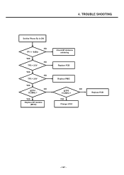
TROUBLE SHOOTING For testing, Max power output is 450 Check TP1 Over 21dBm ? Set the Phone Tx is ON and PDM is needed. YES NO Change the board RF Tx Level is OK Check FEM Check Duplexer Check PAM Block Refer to 3.5.4 - 91 - YES NO Check TP3 Over 16dBm ? YES NO Check TP4 Over -5dBm ? 4. YES NO Check TP2 Over 19dBm ?
TROUBLE SHOOTING For testing, Max power output is 450 Check TP1 Over 21dBm ? Set the Phone Tx is ON and PDM is needed. YES NO Change the board RF Tx Level is OK Check FEM Check Duplexer Check PAM Block Refer to 3.5.4 - 91 - YES NO Check TP3 Over 16dBm ? YES NO Check TP4 Over -5dBm ? 4. YES NO Check TP2 Over 19dBm ?

Service Manual
Page 95
4. YES NO Check TP4 Signal exist? YES NO Check TP3 Signal exist? YES Change the board Check bias block soldering Check RF s/w Check FEM Check Duplexer Check RFR6250 - 96 - TROUBLE SHOOTING Set the Phone Rx is ON NO Check BIAS Over 2V ? YES NO Check TP1 Signal exist? YES NO Check TP2 Signal exist?
4. YES NO Check TP4 Signal exist? YES NO Check TP3 Signal exist? YES Change the board Check bias block soldering Check RF s/w Check FEM Check Duplexer Check RFR6250 - 96 - TROUBLE SHOOTING Set the Phone Rx is ON NO Check BIAS Over 2V ? YES NO Check TP1 Signal exist? YES NO Check TP2 Signal exist?

Service Manual
Page 103
TROUBLE SHOOTING Set the Phone Rx is ON NO Check soldering YES NO Check FEM & buffer YES Change the board Resoldering Change FEM & buffer - 104 - 4.
TROUBLE SHOOTING Set the Phone Rx is ON NO Check soldering YES NO Check FEM & buffer YES Change the board Resoldering Change FEM & buffer - 104 - 4.

Service Manual
Page 104
Set channel to bluetooth test-mode : Enter Test Mode(7973845#*#) → Module Test Set → BT DUT → BT DUT ON 2. Check TP1 : output-power > -6 dBm < KU950 Sub Key Bluetooth Module > < KU950 Main Board Bluetooth Buffer > - 105 - 4.7 Bluetooth RF Block TC-3000A (Bluetooth Tester) 4. TROUBLE SHOOTING 1. Set phone to 39 4. Measure output-power 5. Connect phone to bluetooth tester 3.
Set channel to bluetooth test-mode : Enter Test Mode(7973845#*#) → Module Test Set → BT DUT → BT DUT ON 2. Check TP1 : output-power > -6 dBm < KU950 Sub Key Bluetooth Module > < KU950 Main Board Bluetooth Buffer > - 105 - 4.7 Bluetooth RF Block TC-3000A (Bluetooth Tester) 4. TROUBLE SHOOTING 1. Set phone to 39 4. Measure output-power 5. Connect phone to bluetooth tester 3.
Service Manual
Page 106
TROUBLE SHOOTING Set the Phone Rx is ON NO TP1 < -6dBm YES NO TP2 > 2.5V YES NO TP3 > 2.8V YES NO @TP4 19.2MHz ? YES Replace BT module (M100) Check BT Antenna soldering Replace PCB Replace PMIC NO @TP5 19.2MHz ? YES Change U104 Replace PCB - 107 - 4.
TROUBLE SHOOTING Set the Phone Rx is ON NO TP1 < -6dBm YES NO TP2 > 2.5V YES NO TP3 > 2.8V YES NO @TP4 19.2MHz ? YES Replace BT module (M100) Check BT Antenna soldering Replace PCB Replace PMIC NO @TP5 19.2MHz ? YES Change U104 Replace PCB - 107 - 4.

Service Manual
Page 107
....7V, VREG_MSME_1.8V VREG_TCXO_2.85V, VREG_MSMA_2.6V power up and system reset assert to MSM → Phone booting and PS_HOLD(D601) assert High to PMIC(PM6650-1M). YES Press PWR key Keypad LED on sequence of KU950 is : PWR(END) key press → PM_ON_SW_N go to low when key press? TROUBLE SHOOTING...
....7V, VREG_MSME_1.8V VREG_TCXO_2.85V, VREG_MSMA_2.6V power up and system reset assert to MSM → Phone booting and PS_HOLD(D601) assert High to PMIC(PM6650-1M). YES Press PWR key Keypad LED on sequence of KU950 is : PWR(END) key press → PM_ON_SW_N go to low when key press? TROUBLE SHOOTING...
Service Manual
Page 118
... Ear1ON/Ear1OP → CN801(b'd to b'd connector for LCD Module) → CN101(LCD b'd to b'd connector of LCD FPCB) → R100, R101 → Receiver Start Connect the phone to network Equipment and setup call Setup 1KHz tone out Hear the tone to the receiver NO YES Change the Receiver END The sine wave...
... Ear1ON/Ear1OP → CN801(b'd to b'd connector for LCD Module) → CN101(LCD b'd to b'd connector of LCD FPCB) → R100, R101 → Receiver Start Connect the phone to network Equipment and setup call Setup 1KHz tone out Hear the tone to the receiver NO YES Change the Receiver END The sine wave...

Service Manual
Page 120
NO Check #8 pin of CN601 headset Jack Start Connect the phone to network Equipment and setup call Setup 1KHz tone out And insert head_Set Headset insertion detection in the Main LCD Display OK? or change the ...
NO Check #8 pin of CN601 headset Jack Start Connect the phone to network Equipment and setup call Setup 1KHz tone out And insert head_Set Headset insertion detection in the Main LCD Display OK? or change the ...

Service Manual
Page 122
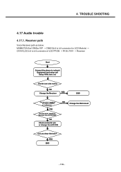
... Main board NO Check C722,C723,U701 or Change the Main board NO Check U702 NO Change the speaker - 123 - Loud speaker path (voice speaker phone, VT, multimedia play, etc) Loud speaker path as below: MSM6275A HPH_R, HPH_L → C709,C710 → U701 ( audio codec) → R710, R711 → ...U702 (Speaker AMP) → FB701, FB703 → Speaker Start Connect the phone to network Equipment and setup call Setup 1KHz tone out Set phone with speaker phone mode The sine wave appear at R710,R711? YES The sine wave appear at C709,C710? YES The sine...
... Main board NO Check C722,C723,U701 or Change the Main board NO Check U702 NO Change the speaker - 123 - Loud speaker path (voice speaker phone, VT, multimedia play, etc) Loud speaker path as below: MSM6275A HPH_R, HPH_L → C709,C710 → U701 ( audio codec) → R710, R711 → ...U702 (Speaker AMP) → FB701, FB703 → Speaker Start Connect the phone to network Equipment and setup call Setup 1KHz tone out Set phone with speaker phone mode The sine wave appear at R710,R711? YES The sine wave appear at C709,C710? YES The sine...

Service Manual
Page 128
... or CHG_CNT_N signal - Charging current path - Connecting TA or USB Cable - Check the charging current path - Connect TA or USB Cable and battery to the phone • Trouble Shooting Procedure - Check the charger connector - Control the charging current by control BATT_FET_N • Check Point - Check the battery - 129 - 4. Connection of TA...
... or CHG_CNT_N signal - Charging current path - Connecting TA or USB Cable - Check the charging current path - Connect TA or USB Cable and battery to the phone • Trouble Shooting Procedure - Check the charger connector - Control the charging current by control BATT_FET_N • Check Point - Check the battery - 129 - 4. Connection of TA...

Service Manual
Page 135
... a download tool with capabilities to upload image files to the handset. LGMDP supports Windows 2000/XP where the LG (Ver 4.6 or later) USB modem driver is installed. 5.2 Downloading Procedure 5.2.1 Setup Preferences • Connect the phone to your desktop PC using the USB cable and run "Select Port" When LGMDP starts This option...
... a download tool with capabilities to upload image files to the handset. LGMDP supports Windows 2000/XP where the LG (Ver 4.6 or later) USB modem driver is installed. 5.2 Downloading Procedure 5.2.1 Setup Preferences • Connect the phone to your desktop PC using the USB cable and run "Select Port" When LGMDP starts This option...

Service Manual
Page 147
... button. DOWNLOAD Log Extractor is very useful for debugging. Select directory to extract log information from the Tools of the file menu, and connect the phone with LGMDP by clicking on the handset. This function is designed to store log files by clicking on the Connect button, this checks if the...
... button. DOWNLOAD Log Extractor is very useful for debugging. Select directory to extract log information from the Tools of the file menu, and connect the phone with LGMDP by clicking on the handset. This function is designed to store log files by clicking on the Connect button, this checks if the...

Service Manual
Page 148
5. In this mode, minimum units for downloading is being booted). and then try to the phone. - 149 - DOWNLOAD 5.3 Troubleshooting download errors 1) When the phone does not work ➜ Reboot the phone as the emergency mode (keep pressing "2" and "5" key while the phone is running so that users can download the images again in case of emergency situation. (AMSS Modem, Media and Module Images don't be running in this mode.) ➜ Connect to download the images again. ★ The phone supports a special mode named emergency mode.
5. In this mode, minimum units for downloading is being booted). and then try to the phone. - 149 - DOWNLOAD 5.3 Troubleshooting download errors 1) When the phone does not work ➜ Reboot the phone as the emergency mode (keep pressing "2" and "5" key while the phone is running so that users can download the images again in case of emergency situation. (AMSS Modem, Media and Module Images don't be running in this mode.) ➜ Connect to download the images again. ★ The phone supports a special mode named emergency mode.

Service Manual
Page 150
2) NV Restore Error 5. DOWNLOAD ➜ Connect to the phone. - 151 -
2) NV Restore Error 5. DOWNLOAD ➜ Connect to the phone. - 151 -


