

Service Manual
Page 2
...-H broadcasting signal reception trouble 132 4.20 Vibrator trouble 135 5. BLOCK DIAGRAM 156 6.1 GSM & WCDMA RF Block 156 6.2 Interface Diagram 158 7. Calibration Program 185 9.1 Configuration of KU950 73 4. EXPLODED VIEW & REPLACEMENT PART LIST ..... 193 10.1 EXPLODED VIEW 193 10.2 Replacement Parts Circuit Diagram 163 8. PERFORMANCE 7 2.1 System Overview 7 2.2 Usable environment 8 2.3 Radio Performance 8 2.4 Current...
...-H broadcasting signal reception trouble 132 4.20 Vibrator trouble 135 5. BLOCK DIAGRAM 156 6.1 GSM & WCDMA RF Block 156 6.2 Interface Diagram 158 7. Calibration Program 185 9.1 Configuration of KU950 73 4. EXPLODED VIEW & REPLACEMENT PART LIST ..... 193 10.1 EXPLODED VIEW 193 10.2 Replacement Parts Circuit Diagram 163 8. PERFORMANCE 7 2.1 System Overview 7 2.2 Usable environment 8 2.3 Radio Performance 8 2.4 Current...

Service Manual
Page 6
... MIC Receiver Earphone Jack Connectivity Volume Key External Memory I/O Connect Specification GSM900/1800/1900 and WCDMA Folder Handset 100.6 x 50.6 x 21.4 mm 110 g (with 950mAh Battery) 3.7V normal, 950 mAh Li-Polymer Over 150 min (WCDMA, Tx=12 dBm, Voice) Over 175 min (GSM, Tx=Max, Voice) Over 200 Hrs (WCDMA...
... MIC Receiver Earphone Jack Connectivity Volume Key External Memory I/O Connect Specification GSM900/1800/1900 and WCDMA Folder Handset 100.6 x 50.6 x 21.4 mm 110 g (with 950mAh Battery) 3.7V normal, 950 mAh Li-Polymer Over 150 min (WCDMA, Tx=12 dBm, Voice) Over 175 min (GSM, Tx=Max, Voice) Over 200 Hrs (WCDMA...

Service Manual
Page 13
...; 2 dBm -107 ± 2 dBm -112 ± 2 dBm VT Under 569mA (Tx=10dBm) GSM -91 ± 2 dBm -96 ± 2 dBm -101 ± 2 dBm -106 ± 2 dBm 2.6 Battery BAR Indication Bar 4 Bar 4 → 3 Bar 3 → 2 Bar 2 → 1 Bar 1 → Empty Low Voltage, Warning message+ Blinking Power Off Standby Over 3.82 ± 0.05V 3.81...
...; 2 dBm -107 ± 2 dBm -112 ± 2 dBm VT Under 569mA (Tx=10dBm) GSM -91 ± 2 dBm -96 ± 2 dBm -101 ± 2 dBm -106 ± 2 dBm 2.6 Battery BAR Indication Bar 4 Bar 4 → 3 Bar 3 → 2 Bar 2 → 1 Bar 1 → Empty Low Voltage, Warning message+ Blinking Power Off Standby Over 3.82 ± 0.05V 3.81...

Service Manual
Page 15
Maximum Charging Voltage : 4.2V - Low battery POP UP : 3.48V - Cut-off voltage : 3.22V - 16 - Full charge indication current (icon stop current) : 60mA - Maximum Charging Current : 650mA - 2. Charger Voltage : 4.8V - Charging time : Max 3 h (Except time trickle charging) - Nominal Battery Capacity : 950 mAh - PERFORMANCE 2.8 Charging - Charging Method : CC & CV (Constant Current & Constant Voltage) - Low battery alarm interval : Idle - 3 min, Dedicated - 1min -
Maximum Charging Voltage : 4.2V - Low battery POP UP : 3.48V - Cut-off voltage : 3.22V - 16 - Full charge indication current (icon stop current) : 60mA - Maximum Charging Current : 650mA - 2. Charger Voltage : 4.8V - Charging time : Max 3 h (Except time trickle charging) - Nominal Battery Capacity : 950 mAh - PERFORMANCE 2.8 Charging - Charging Method : CC & CV (Constant Current & Constant Voltage) - Low battery alarm interval : Idle - 3 min, Dedicated - 1min -

Service Manual
Page 18
It monitors and controls the external power source and coordinates battery recharging while maintaining the handset supply voltages using low dropout, programmable regulators. The device's general housekeeping functions include an ADC and ...regulated by the PM6250 Power Management IC. Key parameters such as temperature, RF output power, and battery ID. Various oscillator, clock, and counter circuits support IC and higher-level handset functions. 3. TECHNICAL BRIEF KU950 power supply voltages are monitored to protect against detrimental conditions. - 19 - This versatile device ...
It monitors and controls the external power source and coordinates battery recharging while maintaining the handset supply voltages using low dropout, programmable regulators. The device's general housekeeping functions include an ADC and ...regulated by the PM6250 Power Management IC. Key parameters such as temperature, RF output power, and battery ID. Various oscillator, clock, and counter circuits support IC and higher-level handset functions. 3. TECHNICAL BRIEF KU950 power supply voltages are monitored to protect against detrimental conditions. - 19 - This versatile device ...

Service Manual
Page 30
... 6mm x 6mm module with integrated power control that provides over 50dBof control range. The ENABLE input allows initial turn-on of PAM circuitry to minimize battery drain. The devices is a high-power, high-efficiency power amplifier module with 50Ω input and output terminals. Figure 3.5.6-1 GSM PA functional block diagram - 31...
... 6mm x 6mm module with integrated power control that provides over 50dBof control range. The ENABLE input allows initial turn-on of PAM circuitry to minimize battery drain. The devices is a high-power, high-efficiency power amplifier module with 50Ω input and output terminals. Figure 3.5.6-1 GSM PA functional block diagram - 31...

Service Manual
Page 38
... a UART interface. The Rx/Tx paths are multiplexed to the input of these pins is designed specifically to analog parameters such as battery voltage, temperature, and RF power levels. In addition, the QDSP4000 has modules to meet the ITU-G.712 requirements for digital transmission systems...SBI, the RTR6250, RFR6200, RFL6200, and PM6650 devices can be a quick, low pin count control Protocol for minimum power consumption, extending battery life in the various software releases. - 39 - The codec integrates the microphone and earphone amplifiers into the MSM. The MSM6275 device has...
... a UART interface. The Rx/Tx paths are multiplexed to the input of these pins is designed specifically to analog parameters such as battery voltage, temperature, and RF power levels. In addition, the QDSP4000 has modules to meet the ITU-G.712 requirements for digital transmission systems...SBI, the RTR6250, RFR6200, RFL6200, and PM6650 devices can be a quick, low pin count control Protocol for minimum power consumption, extending battery life in the various software releases. - 39 - The codec integrates the microphone and earphone amplifiers into the MSM. The MSM6275 device has...

Service Manual
Page 45
... Name AMUX_OUT VBATT_SENSE HDET1 RMT_ADC_MSM PCB REVISION VBAT_TEMP Note RF PAM Temperature sensing Battery voltage level sensing RF WCDMA PAM Power Level sensing Headset remote key detection MAIN PCB Revision checking Battery Temperature sensing Table. 3. HKADC (House Keeping ADC) The MSM6275 device has... an on-chip 8-bit analog-to-digital converter (HKADC) which are multiplexed to analog parameters such as battery voltage, temperature, and RF power levels....
... Name AMUX_OUT VBATT_SENSE HDET1 RMT_ADC_MSM PCB REVISION VBAT_TEMP Note RF PAM Temperature sensing Battery voltage level sensing RF WCDMA PAM Power Level sensing Headset remote key detection MAIN PCB Revision checking Battery Temperature sensing Table. 3. HKADC (House Keeping ADC) The MSM6275 device has... an on-chip 8-bit analog-to-digital converter (HKADC) which are multiplexed to analog parameters such as battery voltage, temperature, and RF power levels....

Service Manual
Page 46
..., all the most common sources - TECHNICAL BRIEF 3.10.3. Major power components are within acceptable operational limits, and coordinates battery and coin cell recharging while maintaining the handset electronics supply voltages. A dedicated controller manages the TCXO warm-up - 3....supply 3.10.3.2. PM6650-1M The PM6650-1M device (Figure 1-1) integrates all the regulated voltages needed to protect against detrimental conditions. battery, external charger, adapter, coin cell back-up and signal buffering, and key parameters (undervoltage lockout and crystal oscillator signal presence...
..., all the most common sources - TECHNICAL BRIEF 3.10.3. Major power components are within acceptable operational limits, and coordinates battery and coin cell recharging while maintaining the handset electronics supply voltages. A dedicated controller manages the TCXO warm-up - 3....supply 3.10.3.2. PM6650-1M The PM6650-1M device (Figure 1-1) integrates all the regulated voltages needed to protect against detrimental conditions. battery, external charger, adapter, coin cell back-up and signal buffering, and key parameters (undervoltage lockout and crystal oscillator signal presence...

Service Manual
Page 48
.... TECHNICAL BRIEF 3.10.3.3. The voltage on this voltage is used and when to set limits for battery charging. PM6650-1M circuits monitor voltages at VCHARGER and ICHARGE pins to the housekeeping ADC via the analog multiplexer. KU950 Battery Bar Display (Standby condition) - 49 - Charging control A programmable charging block in PM6650-1M is routed...
.... TECHNICAL BRIEF 3.10.3.3. The voltage on this voltage is used and when to set limits for battery charging. PM6650-1M circuits monitor voltages at VCHARGER and ICHARGE pins to the housekeeping ADC via the analog multiplexer. KU950 Battery Bar Display (Standby condition) - 49 - Charging control A programmable charging block in PM6650-1M is routed...

Service Manual
Page 49
Parameter Min Typ Max Unit Trickle Current 60 80 100 mA - 50 - Trickle charging can be used for lithium-ion and nickelbased batteries, with its performance specified below (3.2V). TECHNICAL BRIEF 3.10.3.3.1 Trickle charging Trickle Charging of the main battery, enabled through SBI control and powered from VDD to 80mA. 3. The charging current is on-chip programmable current source that supplies current from VDD, is provided by the PM6650-1M IC, The trickle charger is set to pin (VBAT).
Parameter Min Typ Max Unit Trickle Current 60 80 100 mA - 50 - Trickle charging can be used for lithium-ion and nickelbased batteries, with its performance specified below (3.2V). TECHNICAL BRIEF 3.10.3.3.1 Trickle charging Trickle Charging of the main battery, enabled through SBI control and powered from VDD to 80mA. 3. The charging current is on-chip programmable current source that supplies current from VDD, is provided by the PM6650-1M IC, The trickle charger is set to pin (VBAT).

Service Manual
Page 50
...Method : CC & CV (Constant Current & Constant Voltage) • Maximum Charging Voltage : 4.2V • Maximum Charging Current : 650mA • Nominal Battery Capacity : 950 mAh • Charger Voltage : 4.8V • Charging time : Max 3 h (Except time trickle charging) • Full charge indication ...Cut-off voltage : 3.22V - 51 - The constant current charging continues until the battery reaches its target voltage, 4.2V. 3.10.3.3.3 Constant voltage charging Constant voltage charging begins when the battery voltage reaches a target voltage, 4.2V. The end of constant voltage charging is ...
...Method : CC & CV (Constant Current & Constant Voltage) • Maximum Charging Voltage : 4.2V • Maximum Charging Current : 650mA • Nominal Battery Capacity : 950 mAh • Charger Voltage : 4.8V • Charging time : Max 3 h (Except time trickle charging) • Full charge indication ...Cut-off voltage : 3.22V - 51 - The constant current charging continues until the battery reaches its target voltage, 4.2V. 3.10.3.3.3 Constant voltage charging Constant voltage charging begins when the battery voltage reaches a target voltage, 4.2V. The end of constant voltage charging is ...

Service Manual
Page 75
... FL200 U200 X201 X200 U201 U204 Reference CN802 CN600 FL802 U802 CN801 X400 U300 U403 J500 U500 U400 CN500 Description 1.3M Camera Connector Connector for Battery FILTER (EMI) Charge Pump (LCD Backlight / Flash LED / Camera LDO) To LCD FPCB ( Wire ASSY) Crystal (12 MHz) MSM6275 DVB-H BB Backend Chip USIM Connector...
... FL200 U200 X201 X200 U201 U204 Reference CN802 CN600 FL802 U802 CN801 X400 U300 U403 J500 U500 U400 CN500 Description 1.3M Camera Connector Connector for Battery FILTER (EMI) Charge Pump (LCD Backlight / Flash LED / Camera LDO) To LCD FPCB ( Wire ASSY) Crystal (12 MHz) MSM6275 DVB-H BB Backend Chip USIM Connector...

Service Manual
Page 76
KEY Bottom Side BAT100 M100 MIC100 ANT100 CN100 S100 D100 Reference BAT100 M100 MIC100 ANT100 Description Backup Battery Bluetooth RF Module Microphone ( SMD ) Bluetooth Antenna Reference SW100 CN100 S100 D102 Description Joy Stick Main To KEY B To B Connector Trans Flash Socket Diode (TVS) - 77 - KEY Top Side Metal DOME 3. TECHNICAL BRIEF SW100 2.4. 2.3.
KEY Bottom Side BAT100 M100 MIC100 ANT100 CN100 S100 D100 Reference BAT100 M100 MIC100 ANT100 Description Backup Battery Bluetooth RF Module Microphone ( SMD ) Bluetooth Antenna Reference SW100 CN100 S100 D102 Description Joy Stick Main To KEY B To B Connector Trans Flash Socket Diode (TVS) - 77 - KEY Top Side Metal DOME 3. TECHNICAL BRIEF SW100 2.4. 2.3.

Service Manual
Page 107
4. higher than 3.22V? Start Battery voltg. YES VA100 high to PMIC(PM6650-1M). TROUBLE SHOOTING 4. YES Press PWR key Keypad LED on sequence of KU950 is : PWR(END) key press → PM_ON_SW_N go to low(VA100),PM6650-1M KPDPWR_N pin(24) → PM6650-1M Power Up → VREG_MSMC_1....on ? X100 : 19.2M X600 : 32.768Khz NO YES Change the Main board Check the TXCO - 108 - YES NO Change or charging the Battery NO Follow the LED trouble shoot NO Check the Diode VREG_MSMC_1.25V, VREG_MSMP_2.7V, VREG_MSME_1.8V VREG_TCXO_2.85V, VREG_MSMA_2.6V power up and system reset...
4. higher than 3.22V? Start Battery voltg. YES VA100 high to PMIC(PM6650-1M). TROUBLE SHOOTING 4. YES Press PWR key Keypad LED on sequence of KU950 is : PWR(END) key press → PM_ON_SW_N go to low(VA100),PM6650-1M KPDPWR_N pin(24) → PM6650-1M Power Up → VREG_MSMC_1....on ? X100 : 19.2M X600 : 32.768Khz NO YES Change the Main board Check the TXCO - 108 - YES NO Change or charging the Battery NO Follow the LED trouble shoot NO Check the Diode VREG_MSMC_1.25V, VREG_MSMP_2.7V, VREG_MSME_1.8V VREG_TCXO_2.85V, VREG_MSMA_2.6V power up and system reset...

Service Manual
Page 128
...control TA (4.6V) TA Charging control Charging current sensing Q602 Q602 VBATT D3 D4 D1 D2 S G SI3493DV-E3 Battery FET (ON) BATT_FET_N Main Battery Battery charging control • Charging Procedure - Connecting TA or USB Cable - Control the charging current by control BATT_FET_N &#...8226; Check Point - Check the battery - 129 - 4. Charging Current flows into the battery by PM6650-1M IC using USB_CNT_N or CHG_CNT_N signal - Check the charging current path - Battery • Trouble Shooting Setup - Check the charger connector - ...
...control TA (4.6V) TA Charging control Charging current sensing Q602 Q602 VBATT D3 D4 D1 D2 S G SI3493DV-E3 Battery FET (ON) BATT_FET_N Main Battery Battery charging control • Charging Procedure - Connecting TA or USB Cable - Control the charging current by control BATT_FET_N &#...8226; Check Point - Check the battery - 129 - 4. Charging Current flows into the battery by PM6650-1M IC using USB_CNT_N or CHG_CNT_N signal - Check the charging current path - Battery • Trouble Shooting Setup - Check the charger connector - ...

Service Manual
Page 129
TROUBLE SHOOTING Start Check the pin and battery Connect terminals of I /O connector NO Change TA/USB cable Yes END - 130 - Yes Check the Q600,Q601,Q602 Yes Charging OK? Yes Is the TA voltage 4.6V? 4. Is the USB voltage 5.0V? NO Change the board NO Change I /O connector Connection OK?
TROUBLE SHOOTING Start Check the pin and battery Connect terminals of I /O connector NO Change TA/USB cable Yes END - 130 - Yes Check the Q600,Q601,Q602 Yes Charging OK? Yes Is the TA voltage 4.6V? 4. Is the USB voltage 5.0V? NO Change the board NO Change I /O connector Connection OK?

Service Manual
Page 186
9. Calibration Program 9.1.3 Items of setup file [ezlooks] => The yes or no for using ezlooks Domestic: on, Overseas: off [batcal] => The yes or no for using battery calibration [svc] => The yes or no for using HOT KIMCHI at service center Domestic: off, Service Center: on [standalone] => Overseas factory or Service Center: on, Domestic: off [tescom] => The yes or no for using TESCOM shield box [process] => selection of the process (auto or cal) - 187 -
9. Calibration Program 9.1.3 Items of setup file [ezlooks] => The yes or no for using ezlooks Domestic: on, Overseas: off [batcal] => The yes or no for using battery calibration [svc] => The yes or no for using HOT KIMCHI at service center Domestic: off, Service Center: on [standalone] => Overseas factory or Service Center: on, Domestic: off [tescom] => The yes or no for using TESCOM shield box [process] => selection of the process (auto or cal) - 187 -

Service Manual
Page 197
... SAEY00 PCB ASSY,KEYPAD 5 SAEB00 PCB ASSY, KEYPAD,INSERT 5 SAEE00 PCB ASSY,KEYPAD,SMT 6 SAEC00 PCB ASSY,KEYPAD,SMT BOTTOM 7 ANT100 ANTENNA,GSM,FIXED 7 BAT100 BATTERY,CELL,LITHIUM 7 C100 CAP,CERAMIC,CHIP 7 C101 CAP,CERAMIC,CHIP 7 C102 CAP,TANTAL,CHIP 7 C103 CAP,CERAMIC,CHIP 7 C104 CAP,CERAMIC,CHIP 7 C105 CAP,CERAMIC...
... SAEY00 PCB ASSY,KEYPAD 5 SAEB00 PCB ASSY, KEYPAD,INSERT 5 SAEE00 PCB ASSY,KEYPAD,SMT 6 SAEC00 PCB ASSY,KEYPAD,SMT BOTTOM 7 ANT100 ANTENNA,GSM,FIXED 7 BAT100 BATTERY,CELL,LITHIUM 7 C100 CAP,CERAMIC,CHIP 7 C101 CAP,CERAMIC,CHIP 7 C102 CAP,TANTAL,CHIP 7 C103 CAP,CERAMIC,CHIP 7 C104 CAP,CERAMIC,CHIP 7 C105 CAP,CERAMIC...
Service Manual
Page 219
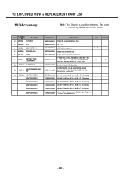
...4 MBAZ00 BAG 4 MCHZ00 COMPACT DISK 4 MSFG00 STICKER,SEAL 4 MLAZ00 LABEL 3 SBPP00 BATTERY PACK, LI-POLYMER SGDY00 DATA CABLE SGEY00 EAR PHONE/EAR MIKE SET SSAD00 ADAPTOR,AC... ADAPTOR,AC-DC ADAPTOR,AC-DC ADAPTOR,AC-DC Part Number Specification Color Remark ADEY0008401 KU950 CD Ass'y for reference, Part order is used for Vodafone, Italy MBAZ0004701 CD Cover...MCHZ0030501 COMPLEX, (empty), , , , , Silver Snow MSFG0000801 Steaker seal of Data kit case MLAZ0002601 LG-500 ITA, LG-600 ITA, LG-G510 ITA 3.7 V,950 mAh,1 CELL,PRISMATIC ,U950 BATT, HIT, SBPP0020501 Silver Color, Pb-Free ...
...4 MBAZ00 BAG 4 MCHZ00 COMPACT DISK 4 MSFG00 STICKER,SEAL 4 MLAZ00 LABEL 3 SBPP00 BATTERY PACK, LI-POLYMER SGDY00 DATA CABLE SGEY00 EAR PHONE/EAR MIKE SET SSAD00 ADAPTOR,AC... ADAPTOR,AC-DC ADAPTOR,AC-DC ADAPTOR,AC-DC Part Number Specification Color Remark ADEY0008401 KU950 CD Ass'y for reference, Part order is used for Vodafone, Italy MBAZ0004701 CD Cover...MCHZ0030501 COMPLEX, (empty), , , , , Silver Snow MSFG0000801 Steaker seal of Data kit case MLAZ0002601 LG-500 ITA, LG-600 ITA, LG-G510 ITA 3.7 V,950 mAh,1 CELL,PRISMATIC ,U950 BATT, HIT, SBPP0020501 Silver Color, Pb-Free ...

