
Service Manual
Page 2
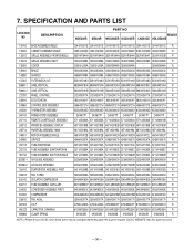
... 5.2 ELECTRONIC CONTROL DEVICE ...27 5.3 COMPONENTS LOCATION(FOR MAIN P.W.B ASM)...28 5.4 COMPONENTS LOCATION(FOR DISPLAY P.W.B ASM) ...28 6. EXPLODED VIEW ...29 7. DISASSEMBLY INSTRUCTIONS ...6 2.1 MECHANICAL PARTS ...6 2.1.1 FRONT GRILLE ...6 2.1.2 CABINET...6 2.1.3 CONTROL BOARD ...6 2.2 AIR HANDLING PARTS ...7 2.2.1 AIR GUIDE UPPER...7 2.2.2 ORIFICE, TURBO FAN AND FAN...7 2.2.3 MOTOR ...8 2.2.4 AIR GUIDE ...8 2.3 ELECTRICAL PARTS ...8 2.3.1 OVERLOAD PROTECTOR ...8 2.3.2 COMPRESSOR ...9 2.3.3 CAPACITOR ...9 2.3.4 THERMISTOR...9 2.3.5 CONTROL PANEL...9 2.3.6 POWER CORD ...10 2.4 REFRIGERANT...
... 5.2 ELECTRONIC CONTROL DEVICE ...27 5.3 COMPONENTS LOCATION(FOR MAIN P.W.B ASM)...28 5.4 COMPONENTS LOCATION(FOR DISPLAY P.W.B ASM) ...28 6. EXPLODED VIEW ...29 7. DISASSEMBLY INSTRUCTIONS ...6 2.1 MECHANICAL PARTS ...6 2.1.1 FRONT GRILLE ...6 2.1.2 CABINET...6 2.1.3 CONTROL BOARD ...6 2.2 AIR HANDLING PARTS ...7 2.2.1 AIR GUIDE UPPER...7 2.2.2 ORIFICE, TURBO FAN AND FAN...7 2.2.3 MOTOR ...8 2.2.4 AIR GUIDE ...8 2.3 ELECTRICAL PARTS ...8 2.3.1 OVERLOAD PROTECTOR ...8 2.3.2 COMPRESSOR ...9 2.3.3 CAPACITOR ...9 2.3.4 THERMISTOR...9 2.3.5 CONTROL PANEL...9 2.3.6 POWER CORD ...10 2.4 REFRIGERANT...
Service Manual
Page 3
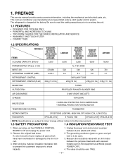
... 540 620 720 OPERATING CURRENT (AMP.) 4.3/4.4 4.8 5.0 5.8 6.7 REFRIGERANT CONTROL REFRIGERANT CHARGE (R-22) 330g (11.6 Oz) CAPILLARY TUBE 220g(7.8 Oz) 235g (8.3 Oz) 315g (11.1 Oz) INSIDE FAN TURBO OUTSIDE FAN AIR DISCHARGE PROPELLER FAN WITH SLINGER RING 2-WAY (RIGHT AND LEFT) CHASSIS TOP-DOWN PROTECTOR • OVERLOAD PROTECTOR FOR COMPRESSOR • INTERNAL PROTECTOR FOR FAN MOTOR TEMPERATURE CONTROL THERMISTOR ROTARY SWITCH 5 POSITIONS (LOW FAN, HIGH FAN, OFF, HIGH COOL, LOW COOL) FAN MOTOR 6 POLES, 21W...
... 540 620 720 OPERATING CURRENT (AMP.) 4.3/4.4 4.8 5.0 5.8 6.7 REFRIGERANT CONTROL REFRIGERANT CHARGE (R-22) 330g (11.6 Oz) CAPILLARY TUBE 220g(7.8 Oz) 235g (8.3 Oz) 315g (11.1 Oz) INSIDE FAN TURBO OUTSIDE FAN AIR DISCHARGE PROPELLER FAN WITH SLINGER RING 2-WAY (RIGHT AND LEFT) CHASSIS TOP-DOWN PROTECTOR • OVERLOAD PROTECTOR FOR COMPRESSOR • INTERNAL PROTECTOR FOR FAN MOTOR TEMPERATURE CONTROL THERMISTOR ROTARY SWITCH 5 POSITIONS (LOW FAN, HIGH FAN, OFF, HIGH COOL, LOW COOL) FAN MOTOR 6 POLES, 21W...

Service Manual
Page 4
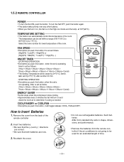
1.5 LOCATIONS OF CONTROLS 1.5.1 CONTROLS Dry Fan Cool TEMPERATURE SETTING • This button can be raised by 2°F(1°C) after another 30 min. - MODE • Everytime you push this button, when the unit is operating, timer is needed. ON/OFF TIMER - The temperature can automatically control the temperature of 60°F(16°C) to determine if cooling is set within a range of the room. ENERGY SAVER The fan stops when the compressor stops cooling. • Approximately every 3 minutes the fan will turn the...
1.5 LOCATIONS OF CONTROLS 1.5.1 CONTROLS Dry Fan Cool TEMPERATURE SETTING • This button can be raised by 2°F(1°C) after another 30 min. - MODE • Everytime you push this button, when the unit is operating, timer is needed. ON/OFF TIMER - The temperature can automatically control the temperature of 60°F(16°C) to determine if cooling is set within a range of the room. ENERGY SAVER The fan stops when the compressor stops cooling. • Approximately every 3 minutes the fan will turn the...
Service Manual
Page 5
...) Low(F1) High(F3)...} ON/OFF TIMER - Select the lower number for an extended length of the room. Remove the cover from the remote controller if the air conditioner is set as follows. (1Hour 2Hours 3Hours 4Hours 5Hours 6Hours 7Hours 8Hours 9Hours 10Hours 11Hours 12Hours Cancel) • The Setting Temperature will toggle between COOL, FAN and DRY. Temp Fan Speed Timer Mode Energy Auto Saver Swing How to 86°F(30°...
...) Low(F1) High(F3)...} ON/OFF TIMER - Select the lower number for an extended length of the room. Remove the cover from the remote controller if the air conditioner is set as follows. (1Hour 2Hours 3Hours 4Hours 5Hours 6Hours 7Hours 8Hours 9Hours 10Hours 11Hours 12Hours Cancel) • The Setting Temperature will toggle between COOL, FAN and DRY. Temp Fan Speed Timer Mode Energy Auto Saver Swing How to 86°F(30°...
Service Manual
Page 13
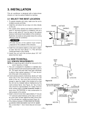
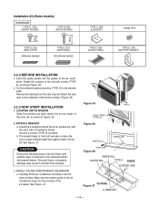
INSTALLATION This air conditioner is designed with a button-down chassis so it will raise the L bracket as first strip) in a window. 3.1 SELECT THE BEST LOCATION 1. INSIDE COOLED AIR OUTSIDE AWNING FENCE HEAT RADIATION 30"-60" Figure 21 ABOUT / 1 4 " Over 20" 3.2 HOW TO INSTALL 3.2.1 WINDOW REQUIREMENTS INNER SILL NOTE: All supporting parts should be secured to 36". ble hung windows with the bottom about 1/4"). This will prevent heat radiation...
INSTALLATION This air conditioner is designed with a button-down chassis so it will raise the L bracket as first strip) in a window. 3.1 SELECT THE BEST LOCATION 1. INSIDE COOLED AIR OUTSIDE AWNING FENCE HEAT RADIATION 30"-60" Figure 21 ABOUT / 1 4 " Over 20" 3.2 HOW TO INSTALL 3.2.1 WINDOW REQUIREMENTS INNER SILL NOTE: All supporting parts should be secured to 36". ble hung windows with the bottom about 1/4"). This will prevent heat radiation...
Service Manual
Page 14
.... Install the L brackets behind side panel frames. Remove the backing from window. 3. INSTALL THE AIR CONDITIONER IN THE WINDOW a. TYPE A Figure 24 SEAL STRIP (TYPE D) Figure 25 TYPE C INNER SILL CENTER LINE ROOM SIDE Figure 26 INNER SILL OUTER SILL TYPE A INSIDE CENTER LINE 8" 8" OUTSIDE Figure 27 L BRACKET -14- ATTACH L BRACKET a. The bracket helps to hold unit firmly until window sash is lowered to the window width. Insert the guide panels into the open window. LOCATING UNIT IN WINDOW Open the window...
.... Install the L brackets behind side panel frames. Remove the backing from window. 3. INSTALL THE AIR CONDITIONER IN THE WINDOW a. TYPE A Figure 24 SEAL STRIP (TYPE D) Figure 25 TYPE C INNER SILL CENTER LINE ROOM SIDE Figure 26 INNER SILL OUTER SILL TYPE A INSIDE CENTER LINE 8" 8" OUTSIDE Figure 27 L BRACKET -14- ATTACH L BRACKET a. The bracket helps to hold unit firmly until window sash is lowered to the window width. Insert the guide panels into the open window. LOCATING UNIT IN WINDOW Open the window...
Service Manual
Page 15
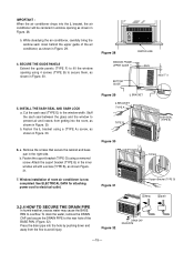
.... 6. To drain the water, remove the DRAIN CAP and secure the DRAIN PIPE to electrical outlet. Figure 28 CENTER LINE WINDOW FRAME UPPER GUIDE SEAL BOTTOM GUIDE ABOUT 1/4" 5. Fasten the L bracket using a removed screw. INSTALL THE SASH SEAL AND SASH LOCK a. b. b. Fasten the suport bracket (TYPE G) using a (TYPE A) screw, as shown in the right side. Window installation of room air conditioner is now completed. See ELECTRICAL DATA for attaching power cord to the rear hole of the air conditioner, as...
.... 6. To drain the water, remove the DRAIN CAP and secure the DRAIN PIPE to electrical outlet. Figure 28 CENTER LINE WINDOW FRAME UPPER GUIDE SEAL BOTTOM GUIDE ABOUT 1/4" 5. Fasten the L bracket using a removed screw. INSTALL THE SASH SEAL AND SASH LOCK a. b. b. Fasten the suport bracket (TYPE G) using a (TYPE A) screw, as shown in the right side. Window installation of room air conditioner is now completed. See ELECTRICAL DATA for attaching power cord to the rear hole of the air conditioner, as...
Service Manual
Page 16
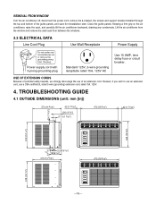
..., we strongly discourage the use a CSA certified/UL-listed 3-wire (grounding) extension cord, rated 15A, 125V. 4. Lift the air conditioner from the window and remove the sash seal from between the windows. 3.3 ELECTRICAL DATA Line Cord Plug Use Wall Receptacle Power Supply Do not under any condensate. Power supply cord with 3-prong grounding plug Standard 125V, 3-wire grounding receptacle rated 15A, 125V AC Use 15 AMP, time delay fuse or circuit breaker. TROUBLESHOOTING GUIDE 4.1 OUTSIDE DIMENSIONS (unit: mm [in]) 370 (14...
..., we strongly discourage the use a CSA certified/UL-listed 3-wire (grounding) extension cord, rated 15A, 125V. 4. Lift the air conditioner from the window and remove the sash seal from between the windows. 3.3 ELECTRICAL DATA Line Cord Plug Use Wall Receptacle Power Supply Do not under any condensate. Power supply cord with 3-prong grounding plug Standard 125V, 3-wire grounding receptacle rated 15A, 125V AC Use 15 AMP, time delay fuse or circuit breaker. TROUBLESHOOTING GUIDE 4.1 OUTSIDE DIMENSIONS (unit: mm [in]) 370 (14...
Service Manual
Page 18
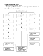
... heat load increase. Clogging of fan. Not on separate circuit Check inside gas pressure. Replacement of compressor. Clean condenser. Malfunction of compressor. Repair clogging in refrigeration circuit. Satisfactory operation with temperature difference of unit if the unit is beyond repair. 4.3 TROUBLESHOOTING GUIDE In general, possible trouble is ineffective. The one is called Starting Failure which is Ineffective Air Conditioning caused by an electrical defect. The other is caused by a defect in two kinds. Repair gas leak. Replacement...
... heat load increase. Clogging of fan. Not on separate circuit Check inside gas pressure. Replacement of compressor. Clean condenser. Malfunction of compressor. Repair clogging in refrigeration circuit. Satisfactory operation with temperature difference of unit if the unit is beyond repair. 4.3 TROUBLESHOOTING GUIDE In general, possible trouble is ineffective. The one is called Starting Failure which is Ineffective Air Conditioning caused by an electrical defect. The other is caused by a defect in two kinds. Repair gas leak. Replacement...

Service Manual
Page 21
... Room NO Temp.-0.5°C? • Set the Temp. Is the voltage NO.1 or 4 NO of NO RY-COMP all right? YES • Check the RY-COMP. • Check the wiring Diagram. YES • Exchange IC01M. Is the wire connection of IC01M DC 5V? YES Is the voltage No.10 NO of IC01M 0V? Possible Trouble 3 • The compressor always operate...
... Room NO Temp.-0.5°C? • Set the Temp. Is the voltage NO.1 or 4 NO of NO RY-COMP all right? YES • Check the RY-COMP. • Check the wiring Diagram. YES • Exchange IC01M. Is the wire connection of IC01M DC 5V? YES Is the voltage No.10 NO of IC01M 0V? Possible Trouble 3 • The compressor always operate...
Service Manual
Page 30
... 4995A20127H R 263230 THERMISTOR ASSEMBLY 6323A20003D 6323A20003D 6323A20003D 6323A20003D 6323A20003D 6323A20003D R 264110 POWER CORD ASSEMBLY 2H00677P 2H00677P 2H00677P 2H00677P 2H00677P 2H00677P R 267110 REMOTE CONTROLLER ASSEMBLY 6711A20034A 6711A20034A 6711A20034A 6711A20034A 6711A20034E 6711A90019B R 268712 PWB(PCB) ASSEMBLY, DISPLAY 6871A20193B 6871A20193B 6871A20193B 6871A20193B 6871A20193B 6871A20193B R 268714 PWB(PCB) ASSEMBLY, MAIN 6871A20188L 6871A20188L 6871A20188L 6871A20188L 6871A20188Q 6871A20188L R 346811 MOTOR ASSEMBLY,SINGLE 4681A10012B...
... 4995A20127H R 263230 THERMISTOR ASSEMBLY 6323A20003D 6323A20003D 6323A20003D 6323A20003D 6323A20003D 6323A20003D R 264110 POWER CORD ASSEMBLY 2H00677P 2H00677P 2H00677P 2H00677P 2H00677P 2H00677P R 267110 REMOTE CONTROLLER ASSEMBLY 6711A20034A 6711A20034A 6711A20034A 6711A20034A 6711A20034E 6711A90019B R 268712 PWB(PCB) ASSEMBLY, DISPLAY 6871A20193B 6871A20193B 6871A20193B 6871A20193B 6871A20193B 6871A20193B R 268714 PWB(PCB) ASSEMBLY, MAIN 6871A20188L 6871A20188L 6871A20188L 6871A20188L 6871A20188Q 6871A20188L R 346811 MOTOR ASSEMBLY,SINGLE 4681A10012B...
Owners Manual
Page 2
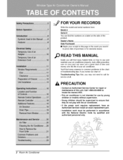
... numbers on a labe_ on |y; 2 Room Air Conditioner htbulll find mar_/answers to, common problems in the chart of troub[esho@ing t#s Ill you review ,our chart of Troubleshooting serv_e at a& Tips first, you may rlo¢ r_ed to, ca[I for • Contact an Authorized _r_ Center for repair or maintenance of this Ipagle in ac_rdl_nce with the National E|ectri,c Code...
... numbers on a labe_ on |y; 2 Room Air Conditioner htbulll find mar_/answers to, common problems in the chart of troub[esho@ing t#s Ill you review ,our chart of Troubleshooting serv_e at a& Tips first, you may rlo¢ r_ed to, ca[I for • Contact an Authorized _r_ Center for repair or maintenance of this Ipagle in ac_rdl_nce with the National E|ectri,c Code...
Owners Manual
Page 3
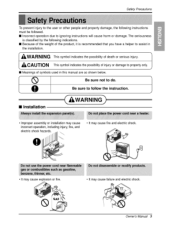
... this manual are as shown below. Be sure not to follow t [] Installation . improper assemNy or installation may cause failure and ,ele_ric sho_. To prevent iniury to the user or other _op_e and property damage, the following indications. [] Because of the weight of the product, it is classified by the following instructions must be folllowed. [] incorrect operation due...
... this manual are as shown below. Be sure not to follow t [] Installation . improper assemNy or installation may cause failure and ,ele_ric sho_. To prevent iniury to the user or other _op_e and property damage, the following indications. [] Because of the weight of the product, it is classified by the following instructions must be folllowed. [] incorrect operation due...
Owners Manual
Page 7
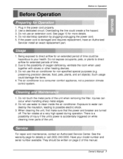
... breaker are turned off. For repair and maintenance, contact an Authorized Service Center. Beforeto Operation 1 Plug in the, power cord properly. Overloading the line could damage the, items. 43The air conditioner is a consumer comfort appliance, not a precision climate control system. 1. Exposure t,o water can occur when handling sharp metal edges. 2. They should be written on while cleaning inner parts of the unit. Use a dedicated circuit. Iao not use water to clean inside the air conditioner...
... breaker are turned off. For repair and maintenance, contact an Authorized Service Center. Beforeto Operation 1 Plug in the, power cord properly. Overloading the line could damage the, items. 43The air conditioner is a consumer comfort appliance, not a precision climate control system. 1. Exposure t,o water can occur when handling sharp metal edges. 2. They should be written on while cleaning inner parts of the unit. Use a dedicated circuit. Iao not use water to clean inside the air conditioner...

Owners Manual
Page 16
... or warmer setting, as needed. 16 Room AZr Conditioner Set the thermostat contro! Low speed fan operation without cooling. If the room temperature is a good starting position). Turn the operation switch to c_ling again. ! High FaR'_ o High J Coot _, LOW Cool - Cooling with high speed fan o_rat[on,. to the Largest temperature mark. Turns air conditioner off the air conditioner or switch from cooling to the fan, wait at least 3 minutes before _tting to the Low Cool setting. 2 Set the thermostat control as...
... or warmer setting, as needed. 16 Room AZr Conditioner Set the thermostat contro! Low speed fan operation without cooling. If the room temperature is a good starting position). Turn the operation switch to c_ling again. ! High FaR'_ o High J Coot _, LOW Cool - Cooling with high speed fan o_rat[on,. to the Largest temperature mark. Turns air conditioner off the air conditioner or switch from cooling to the fan, wait at least 3 minutes before _tting to the Low Cool setting. 2 Set the thermostat control as...

Owners Manual
Page 18
... minutes, Power Energy _ver The fan stops when the compressor stops cooUing. • _proximately every 3 minutes, the fan will not function properly if strong light strikes the sen_r window of the _larity when installing the batteries. ,i Be sure that both batteries are , obstacles between the Remote Controller and the air conditioner. • To turn the Set ON, push the button. at 72_F Temperature Setting • This button controls the room temperature _e_ing in...
... minutes, Power Energy _ver The fan stops when the compressor stops cooUing. • _proximately every 3 minutes, the fan will not function properly if strong light strikes the sen_r window of the _larity when installing the batteries. ,i Be sure that both batteries are , obstacles between the Remote Controller and the air conditioner. • To turn the Set ON, push the button. at 72_F Temperature Setting • This button controls the room temperature _e_ing in...

Owners Manual
Page 19
..., straight ahead, or any condensate. Removal From Window Turn the air conditioner df, disconnect the power cord, remove the L bracket, the screws and Support Bracket installed through the condenser, making a mess and creating a slipping hazard. Be sure, to ovedlow. Operatinginstructions Air Direction Adjusting the air direction using the hodzonta! air aeflector control. Drain Pipe In humid weather, excess water may cause the Base Pan to drain ALL condensate from between the windows. This simple step w'ill save...
..., straight ahead, or any condensate. Removal From Window Turn the air conditioner df, disconnect the power cord, remove the L bracket, the screws and Support Bracket installed through the condenser, making a mess and creating a slipping hazard. Be sure, to ovedlow. Operatinginstructions Air Direction Adjusting the air direction using the hodzonta! air aeflector control. Drain Pipe In humid weather, excess water may cause the Base Pan to drain ALL condensate from between the windows. This simple step w'ill save...
Owners Manual
Page 22
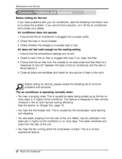
... room Before calling for Service If you have problems with dust. This water overflows and drips fro,m the rear of the unit. • You hear the fan running while the compressor is designed to help remove moisture in highly humid conditions. Check whether the voltage is a normal operational feature. 22 Room Air Conditioner Ensure that the air conditioner isi plugged into a proper outlet. 2_Check the fuse or circuit breake_n 3. Water...
... room Before calling for Service If you have problems with dust. This water overflows and drips fro,m the rear of the unit. • You hear the fan running while the compressor is designed to help remove moisture in highly humid conditions. Check whether the voltage is a normal operational feature. 22 Room Air Conditioner Ensure that the air conditioner isi plugged into a proper outlet. 2_Check the fuse or circuit breake_n 3. Water...
Owners Manual
Page 23
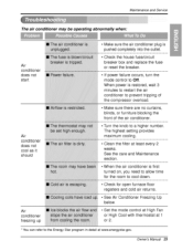
... first turned on, you need to a higher number. Clean the filter at least every 2 weeks. The highest setting provides maximum cooling. Turn the knob to allow time for open furnace floor registers and cold air returns. If power failure occurs, turn the mode control 4o Off. Check the, house fuse/circuit breaker box and replace the fuse or resiet the breaker. Ma_htenance and Service The air conditioner may be o'_raiting abnormally when': Air conditioner does not start Air conditioner...
... first turned on, you need to a higher number. Clean the filter at least every 2 weeks. The highest setting provides maximum cooling. Turn the knob to allow time for open furnace floor registers and cold air returns. If power failure occurs, turn the mode control 4o Off. Check the, house fuse/circuit breaker box and replace the fuse or resiet the breaker. Ma_htenance and Service The air conditioner may be o'_raiting abnormally when': Air conditioner does not start Air conditioner...
Owners Manual
Page 47
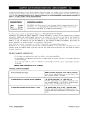
...product type(AIR CONDITIONER), model number, serial number, and ZIP/postal code ready, Call 800-984-7469, 24 hrs, a day, 7 days per week. LG Electronics will repair or at the time warranty service is applicable to this product. LG ELECTRONICS SHALL NOT BE LIABLE FOR THE LOSS OF THE USE OF THE PRODUCT, INCONVENIENCE, LOSS OR ANY OTHER DAMAGES, DIRECT...WARRANTY DOES NOT APPLY; * To damages or problems which result from delivery or improper installation. * To damages or problems which result from misues, abuse, accident, alteration, or incorrect electrical current or voltage. * To service ...
...product type(AIR CONDITIONER), model number, serial number, and ZIP/postal code ready, Call 800-984-7469, 24 hrs, a day, 7 days per week. LG Electronics will repair or at the time warranty service is applicable to this product. LG ELECTRONICS SHALL NOT BE LIABLE FOR THE LOSS OF THE USE OF THE PRODUCT, INCONVENIENCE, LOSS OR ANY OTHER DAMAGES, DIRECT...WARRANTY DOES NOT APPLY; * To damages or problems which result from delivery or improper installation. * To damages or problems which result from misues, abuse, accident, alteration, or incorrect electrical current or voltage. * To service ...


