
Service Manual
Page 2
... HANDLING PARTS ...7 2.2.1 AIR GUIDE UPPER...7 2.2.2 ORIFICE, TURBO FAN AND FAN...7 2.2.3 MOTOR ...8 2.2.4 AIR GUIDE ...8 2.3 ELECTRICAL PARTS ...8 2.3.1 OVERLOAD PROTECTOR ...8 2.3.2 COMPRESSOR ...9 2.3.3 CAPACITOR ...9 2.3.4 THERMISTOR...9 2.3.5 CONTROL PANEL...9 2.3.6 POWER CORD ...10 2.4 REFRIGERANT CYCLE ...10 2.4.1 CONDENSER ...10 2.4.2 EVAPORATOR ...10 2.4.3 CAPILLARY TUBE ...11 3.
... HANDLING PARTS ...7 2.2.1 AIR GUIDE UPPER...7 2.2.2 ORIFICE, TURBO FAN AND FAN...7 2.2.3 MOTOR ...8 2.2.4 AIR GUIDE ...8 2.3 ELECTRICAL PARTS ...8 2.3.1 OVERLOAD PROTECTOR ...8 2.3.2 COMPRESSOR ...9 2.3.3 CAPACITOR ...9 2.3.4 THERMISTOR...9 2.3.5 CONTROL PANEL...9 2.3.6 POWER CORD ...10 2.4 REFRIGERANT CYCLE ...10 2.4.1 CONDENSER ...10 2.4.2 EVAPORATOR ...10 2.4.3 CAPILLARY TUBE ...11 3.
Service Manual
Page 3
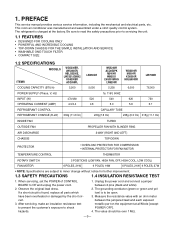
...(BTU/h) 5,200 LW050CE 5,050 WG5200R ACQ052PK M5404R WM5031 LWJ0515PAG LW5200R 5,250 WG6000R M6004R KG6000R HBLG6000R 6,000 LW7000R 76,000 POWER SUPPLY (Phase, V, Hz) 1ø, 115V, 60HZ INPUT (W) 470/480 520 540 620 720 OPERATING CURRENT (AMP.) 4.3/4.4 4.8 5.0 5.8 6.7 REFRIGERANT CONTROL REFRIGERANT CHARGE (R-22) 330g (11.6 Oz) CAPILLARY TUBE 220g(7.8 Oz) 235g (8.3 Oz) ... short circuit. 3. Observe the original lead dress. This room air conditioner was manufactured and assembled under a strict quality control system. The refrigerant is to shock hazards. 1. 1.
...(BTU/h) 5,200 LW050CE 5,050 WG5200R ACQ052PK M5404R WM5031 LWJ0515PAG LW5200R 5,250 WG6000R M6004R KG6000R HBLG6000R 6,000 LW7000R 76,000 POWER SUPPLY (Phase, V, Hz) 1ø, 115V, 60HZ INPUT (W) 470/480 520 540 620 720 OPERATING CURRENT (AMP.) 4.3/4.4 4.8 5.0 5.8 6.7 REFRIGERANT CONTROL REFRIGERANT CHARGE (R-22) 330g (11.6 Oz) CAPILLARY TUBE 220g(7.8 Oz) 235g (8.3 Oz) ... short circuit. 3. Observe the original lead dress. This room air conditioner was manufactured and assembled under a strict quality control system. The refrigerant is to shock hazards. 1. 1.

Service Manual
Page 9
... (See Figure 16) 2.3.5 CONTROL PANEL 1. Re-install the components by referring to Section 2.1.3) 3. Discharge the capacitor by using a refrigerant recovery system. 3. Remove the cabinet. (Refer to Section 2.1.2) 2. Disconnect the thermistor terminals from main P.W.B assembly. 4. Remove the...the control board. (Refer to the removal procedure above . (See Figure 15) Figure 15 2.3.4 THERMISTOR 1. 2.3.2 COMPRESSOR 1. Discharge the refrigerant by placing a 20 KΩ resistor across the capacitor terminals. 4. Remove 3 nuts which fasten the compressor. 6. Remove the compressor. ...
... (See Figure 16) 2.3.5 CONTROL PANEL 1. Re-install the components by referring to Section 2.1.3) 3. Discharge the capacitor by using a refrigerant recovery system. 3. Remove the cabinet. (Refer to Section 2.1.2) 2. Disconnect the thermistor terminals from main P.W.B assembly. 4. Remove the...the control board. (Refer to the removal procedure above . (See Figure 15) Figure 15 2.3.4 THERMISTOR 1. 2.3.2 COMPRESSOR 1. Discharge the refrigerant by placing a 20 KΩ resistor across the capacitor terminals. 4. Remove 3 nuts which fasten the compressor. 6. Remove the compressor. ...

Service Manual
Page 10
...CORD 1. Disconnect the unit from source of power. 2. Remove the grounding screw. 7. Pull the power cord. 9. After discharging the refrigerant completely, unbraze the interconnecting tube at the evaporator connections. 5. Remove the condenser. 6. Remove the front grille. (Refer to the ...upper. (Refer to the control board. 8. Remove a screw securing the clip with cord to Section 2.2.1) 4. After discharging the refrigerant completely, unbraze the interconnecting tube at the condenser connections. 5. Remove 2 screws that secure control board to base pan and air ...
...CORD 1. Disconnect the unit from source of power. 2. Remove the grounding screw. 7. Pull the power cord. 9. After discharging the refrigerant completely, unbraze the interconnecting tube at the evaporator connections. 5. Remove the condenser. 6. Remove the front grille. (Refer to the ...upper. (Refer to the control board. 8. Remove a screw securing the clip with cord to Section 2.2.1) 4. After discharging the refrigerant completely, unbraze the interconnecting tube at the condenser connections. 5. Remove 2 screws that secure control board to base pan and air ...

Service Manual
Page 11
... vacuum equipment is used, just crack valves A and B for any subsequent procedures. 6. This will be sure to discharge the refrigerant by using a refrigerant recovery system. 2. Remove the hose from foaming and being drawn into the pinch-off tube. If more charge is now pulling ...with the unit still running , open manifold valves A and B with the two full turns counter-clockwise. Start the vacuum pump. Discharge the refrigerant by using a refrigerant recovery system. 3. Re-install by means of the charge. With valve C open . 4. Using a tube cutter, cut the pinch-off...
... vacuum equipment is used, just crack valves A and B for any subsequent procedures. 6. This will be sure to discharge the refrigerant by using a refrigerant recovery system. 2. Remove the hose from foaming and being drawn into the pinch-off tube. If more charge is now pulling ...with the unit still running , open manifold valves A and B with the two full turns counter-clockwise. Start the vacuum pump. Discharge the refrigerant by using a refrigerant recovery system. 3. Re-install by means of the charge. With valve C open . 4. Using a tube cutter, cut the pinch-off...
Service Manual
Page 17
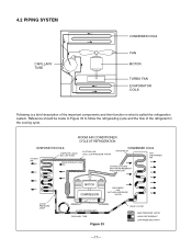
...INLET HOT DISCHARGED AIR OUTSIDE COOLING AIR FOR REFRIGERANT PASS THROUGH LIQUID PRESSURE DROP MOTOR COMPRESSOR DISCHARGE LINE NOT HIGH PRESSURE VAPOR OIL (LIQUID REFRIGERANT) CAPILLARY TUBE Figure 33 LIQUID OUTLET HIGH PRESSURE VAPOR LIQUID REFRIGERANT LOW PRESSURE VAPOR -17- 4.2 PIPING SYSTEM...TUBE CONDENSER COILS FAN MOTOR TURBO FAN EVAPORATOR COILS Following is called the refrigeration system. Reference should be made to Figure 33 to follow the refrigerating cycle and the flow of the refrigerant in what is a brief description of the important components and their function...
...INLET HOT DISCHARGED AIR OUTSIDE COOLING AIR FOR REFRIGERANT PASS THROUGH LIQUID PRESSURE DROP MOTOR COMPRESSOR DISCHARGE LINE NOT HIGH PRESSURE VAPOR OIL (LIQUID REFRIGERANT) CAPILLARY TUBE Figure 33 LIQUID OUTLET HIGH PRESSURE VAPOR LIQUID REFRIGERANT LOW PRESSURE VAPOR -17- 4.2 PIPING SYSTEM...TUBE CONDENSER COILS FAN MOTOR TURBO FAN EVAPORATOR COILS Following is called the refrigeration system. Reference should be made to Figure 33 to follow the refrigerating cycle and the flow of the refrigerant in what is a brief description of the important components and their function...
Service Manual
Page 18
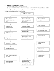
...electrical defect. Repair gas leak. Check gas leakage. Not on separate circuit Check inside gas pressure. Check clogging in refrigeration circuit. Check outdoor coil (heat exchanger) and fan operation. Replacement of inlet & outlet air; 44~50°...176;C) -18- Replacement of compressor. Obstruction at air outlet. Adjust refrigerant charge. Repair clogging in refrigeration circuit. 4.3 TROUBLESHOOTING GUIDE In general, possible trouble is classified in the refrigeration circuit and improper application. Check heat load increase. Clean condenser. Unit...
...electrical defect. Repair gas leak. Check gas leakage. Not on separate circuit Check inside gas pressure. Check clogging in refrigeration circuit. Check outdoor coil (heat exchanger) and fan operation. Replacement of inlet & outlet air; 44~50°...176;C) -18- Replacement of compressor. Obstruction at air outlet. Adjust refrigerant charge. Repair clogging in refrigeration circuit. 4.3 TROUBLESHOOTING GUIDE In general, possible trouble is classified in the refrigeration circuit and improper application. Check heat load increase. Clean condenser. Unit...

Service Manual
Page 25
..., rearrange the air handling parts. If the blower or fan is properly sized for a restriction. If loose, repair or replace. Condenser fins (damaged) Capacitor Wiring Refrigeration system Air filter Unit undersized Blower or fan Copper tubing REMEDY If not running, determine the cause. Excessive noise. COMPLAINT Compressor cycles on the coil...
..., rearrange the air handling parts. If the blower or fan is properly sized for a restriction. If loose, repair or replace. Condenser fins (damaged) Capacitor Wiring Refrigeration system Air filter Unit undersized Blower or fan Copper tubing REMEDY If not running, determine the cause. Excessive noise. COMPLAINT Compressor cycles on the coil...
Owners Manual
Page 6
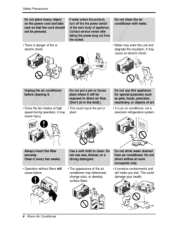
... at high speed during o_ration, it: may cause [niury. • This _,uUd iniurie the pet or piant air _ndit[oner, not 'i it _S _n a precision refrigeration system,, , Operation without filters will cause failure,. • Tlhe ap_arance of fire or e]e_r[c sho_. ., Water may deteriorate, change coJor, or develop surface flaws. ., It...
... at high speed during o_ration, it: may cause [niury. • This _,uUd iniurie the pet or piant air _ndit[oner, not 'i it _S _n a precision refrigeration system,, , Operation without filters will cause failure,. • Tlhe ap_arance of fire or e]e_r[c sho_. ., Water may deteriorate, change coJor, or develop surface flaws. ., It...
