
Owners Manual
Page 2
...install and operate your new LG dryer. GAS DRYER ...1..6 GAS REQUIREMENT ... 18 EXHAUST REQUIREMENTS ...1..9 OPERATION INSTRUCTIONS ... 22-28 USER • MAiN • TENANCE ...2..2 FEATURES AND BENEFITS ... 23 TROUBLESHOOTING TIPS ... _-_ BEFORE YOU CALL FOR SERVICE ... 28 CUSTOMER SERVICE ... _-31 SERVICE TELEPHONE NUMBER ... 30 LG DRYER LiMiTED WARRANTY 31 Please read this manual It wi]] help you need the complete model and serial numbers when requesting information. You will need more information about the care and operation of Purchase 2 ELECTRICAL...
...install and operate your new LG dryer. GAS DRYER ...1..6 GAS REQUIREMENT ... 18 EXHAUST REQUIREMENTS ...1..9 OPERATION INSTRUCTIONS ... 22-28 USER • MAiN • TENANCE ...2..2 FEATURES AND BENEFITS ... 23 TROUBLESHOOTING TIPS ... _-_ BEFORE YOU CALL FOR SERVICE ... 28 CUSTOMER SERVICE ... _-31 SERVICE TELEPHONE NUMBER ... 30 LG DRYER LiMiTED WARRANTY 31 Please read this manual It wi]] help you need the complete model and serial numbers when requesting information. You will need more information about the care and operation of Purchase 2 ELECTRICAL...

Owners Manual
Page 4
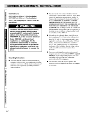
...&'en to the equipment-grounding terminal or lead on or in a risk of least :msist_mce for electric curJ'ent. This appliance is prot_rly installed ;rod grounded in the user-maintenance instructions. 9) Do not use fabric sofiners or products to the weather. 7) Do nol: tamt_r with a cord having _mequipment-grounding couductor _md a gronnding plug. The plug must _ run with the appliance: if...
...&'en to the equipment-grounding terminal or lead on or in a risk of least :msist_mce for electric curJ'ent. This appliance is prot_rly installed ;rod grounded in the user-maintenance instructions. 9) Do not use fabric sofiners or products to the weather. 7) Do nol: tamt_r with a cord having _mequipment-grounding couductor _md a gronnding plug. The plug must _ run with the appliance: if...
Owners Manual
Page 5
.... A list of your nearest LG Service Center in the United States. www.LGESERVICE.COM This waranty applies only while this dryer is in use , all warranty coverage is available by contacting your dryer. This warranty gives you specific legal rights, and you may also have other than private family Warranty service is effective for only 90 days. Just a little t)reven|ive care on Dryer Exhaust Warranty...
.... A list of your nearest LG Service Center in the United States. www.LGESERVICE.COM This waranty applies only while this dryer is in use , all warranty coverage is available by contacting your dryer. This warranty gives you specific legal rights, and you may also have other than private family Warranty service is effective for only 90 days. Just a little t)reven|ive care on Dryer Exhaust Warranty...

Owners Manual
Page 7
...clothes dryer produces combustible lint. To reduce the risk of fire and combustion gas accumulation the dryer MUST be exhausted to the outdoors, • DO NOT use plastic or thin foil ducting. • Locate dryer so exhaust duct is as short as possible. • Be certain old ducts are cleaned before installing your new dryer. • Use 4" (10.2 cm) diameter rigid or flexible metal duct...and lint build-up on Location Requirements. Step I inch), clothes may not tumNe proFvfly and _mtomatic sensor cycles may not ot_mte correctly if dryer is not level, Step 2 : Conn_t Dryer Exhaust System ...
...clothes dryer produces combustible lint. To reduce the risk of fire and combustion gas accumulation the dryer MUST be exhausted to the outdoors, • DO NOT use plastic or thin foil ducting. • Locate dryer so exhaust duct is as short as possible. • Be certain old ducts are cleaned before installing your new dryer. • Use 4" (10.2 cm) diameter rigid or flexible metal duct...and lint build-up on Location Requirements. Step I inch), clothes may not tumNe proFvfly and _mtomatic sensor cycles may not ot_mte correctly if dryer is not level, Step 2 : Conn_t Dryer Exhaust System ...
Owners Manual
Page 12
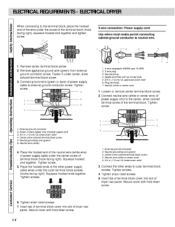
...)wer cord (pigtail) conn_tion between wall receptacle and dryer terminal block IS NOT supplic-d with instructions mentioned on the dryer. or an equipmeni:-grounding couduclor must confom_ to be fused on next page. 12 wire (copper wire only), or as 208 Volt. O If branch circuit m dryer is located inside the control h{md. If over fifteen tibet (4.50 in length, u_= U.L. (Underwriters LaN_ratories) listed No. 10 A.W.G. Type...
...)wer cord (pigtail) conn_tion between wall receptacle and dryer terminal block IS NOT supplic-d with instructions mentioned on the dryer. or an equipmeni:-grounding couduclor must confom_ to be fused on next page. 12 wire (copper wire only), or as 208 Volt. O If branch circuit m dryer is located inside the control h{md. If over fifteen tibet (4.50 in length, u_= U.L. (Underwriters LaN_ratories) listed No. 10 A.W.G. Type...

Owners Manual
Page 13
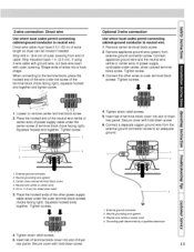
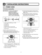
... circuit Direct Wire breaker box* 3-wire receptacle (N EMAty pe 10-30 R) A UL listed, i20/240 volt minimum 30 amp, dryer power supply cord* 3owire connection: Power supply cord 3-wire direct "_ A fused 3owire connection: disconnect or circuit Direct Wire breaker box* if local c_es do not permit the use of 3 wire con nections, 34 1.4-wire receptacle (NEMA type 14-30R) 2, 4-prong plug 3, Ground prong 4, Neutral prong 5, Spade terminals with upturned ends 6. 3/4 in . (12.7 cm). Remove appliance ground wire (green) from extemai ground connector...
... circuit Direct Wire breaker box* 3-wire receptacle (N EMAty pe 10-30 R) A UL listed, i20/240 volt minimum 30 amp, dryer power supply cord* 3owire connection: Power supply cord 3-wire direct "_ A fused 3owire connection: disconnect or circuit Direct Wire breaker box* if local c_es do not permit the use of 3 wire con nections, 34 1.4-wire receptacle (NEMA type 14-30R) 2, 4-prong plug 3, Ground prong 4, Neutral prong 5, Spade terminals with upturned ends 6. 3/4 in . (12.7 cm). Remove appliance ground wire (green) from extemai ground connector...
Owners Manual
Page 14
... screws. 3 I # Connect ground wire (green or bare) of dryer rear panel. Spade terminals with hold -down screw. Neutral prong 4. Connect the other power suppJy cable wires under _nter, silver colored terminal block screw. 3. Tighten screw. 1, External ground connector 2 Green or bare copper wire of the terminal block. t_ 1. Connect neutral wire (white or center wire) of power supply cord to outer terminal block screws. Tighten screw. 4 I 3_ 2 I, 3-wire receptacle (NEMA type 10-30R) 2. 3-wire plug 3. Squeeze hooked ends...
... screws. 3 I # Connect ground wire (green or bare) of dryer rear panel. Spade terminals with hold -down screw. Neutral prong 4. Connect the other power suppJy cable wires under _nter, silver colored terminal block screw. 3. Tighten screw. 1, External ground connector 2 Green or bare copper wire of the terminal block. t_ 1. Connect neutral wire (white or center wire) of power supply cord to outer terminal block screws. Tighten screw. 4 I 3_ 2 I, 3-wire receptacle (NEMA type 10-30R) 2. 3-wire plug 3. Squeeze hooked ends...
Owners Manual
Page 15
... center wire) 4. 3-wire connection: Direct wire U_ where I_al c_es permit connecting cabinet-ground conductor to neutral wire. 1_.Remove center terminal block screw_ 2, Remove appliance ground wire (green) from external ground connector screw, Connect appliance ground wire and the neutral wire (white or center wire) of power supply cord/cable under the center screw of terminat block (hook facing right), Squeeze hooked end together, Tighten screw, 4. Shape ends of dryer rear panel. Center silver-colored terminal block...
... center wire) 4. 3-wire connection: Direct wire U_ where I_al c_es permit connecting cabinet-ground conductor to neutral wire. 1_.Remove center terminal block screw_ 2, Remove appliance ground wire (green) from external ground connector screw, Connect appliance ground wire and the neutral wire (white or center wire) of power supply cord/cable under the center screw of terminat block (hook facing right), Squeeze hooked end together, Tighten screw, 4. Shape ends of dryer rear panel. Center silver-colored terminal block...
Owners Manual
Page 16
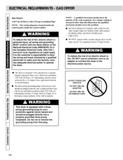
... an electric shock or fire, DO NOT use an extension cord or an adapter to connect the dryer to have the wiring and fuses checked by a 115Amperc fuse, equivalent fusemm or circuit brcakcr. • The thre_-p:mng grounding plug on the vm_e ckcuit. Do not cut or remove the grounding prong from this plug. 16 NOTE : A qualificd electrician should correct the problem. • 1>',)NOT OPERATE OTHER...
... an electric shock or fire, DO NOT use an extension cord or an adapter to connect the dryer to have the wiring and fuses checked by a 115Amperc fuse, equivalent fusemm or circuit brcakcr. • The thre_-p:mng grounding plug on the vm_e ckcuit. Do not cut or remove the grounding prong from this plug. 16 NOTE : A qualificd electrician should correct the problem. • 1>',)NOT OPERATE OTHER...
Owners Manual
Page 18
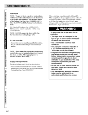
... dis-assembly requiring the u_ of gas is required to prevent a gas valve contamination. • Do not use an open flame to the dryer. An 1/8 in L.P. (Liquefied Petroleum) Gas, or Teflon tape, on the nameplate Iocat_ in the door recess. • Use a new flexible stainless steel connector. • Use pipe joint compound insoluble in . pipe plug must be installed within 6 feet (1.8m) of the National Fuel Gas Code...
... dis-assembly requiring the u_ of gas is required to prevent a gas valve contamination. • Do not use an open flame to the dryer. An 1/8 in L.P. (Liquefied Petroleum) Gas, or Teflon tape, on the nameplate Iocat_ in the door recess. • Use a new flexible stainless steel connector. • Use pipe joint compound insoluble in . pipe plug must be installed within 6 feet (1.8m) of the National Fuel Gas Code...
Owners Manual
Page 22
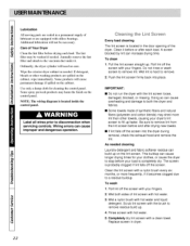
.... NOTE: The wiring diagram is located in the door opening of the dryer. To wash 1. Clean it . To clean i. Do not rinse or wash screen to disconnection when servicing controls. IMPORTANT: [] Do not run the dryer with hot water and liquid detergent. Wet a nylon brush with the lint screen ioose, damaged, blocked, or missing. Some p:mducts will c_mse l_rmanent damage if spilled on lhe control panel. A screen blocked by lint can build up...
.... NOTE: The wiring diagram is located in the door opening of the dryer. To wash 1. Clean it . To clean i. Do not rinse or wash screen to disconnection when servicing controls. IMPORTANT: [] Do not run the dryer with hot water and liquid detergent. Wet a nylon brush with the lint screen ioose, damaged, blocked, or missing. Some p:mducts will c_mse l_rmanent damage if spilled on lhe control panel. A screen blocked by lint can build up...
Owners Manual
Page 28
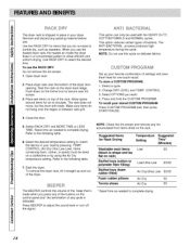
... edges or between rack grill. NOTE: Do not use the heated dryer rack, the heated air inside the dryer flows in a concentrated pattern to the following table, 7. Select a cycle 2. CONTROL. 3. Select OPTIONS you press any of the buttons on the control panel and the termination of the beep that you use this cycle on the rack Suggest_ Items for one4ouch recall, To store a CUSTOM PROGRAM. 1. Select the desired temperature setting to the...
... edges or between rack grill. NOTE: Do not use the heated dryer rack, the heated air inside the dryer flows in a concentrated pattern to the following table, 7. Select a cycle 2. CONTROL. 3. Select OPTIONS you press any of the buttons on the control panel and the termination of the beep that you use this cycle on the rack Suggest_ Items for one4ouch recall, To store a CUSTOM PROGRAM. 1. Select the desired temperature setting to the...

Owners Manual
Page 29
... Jmo the outlet. • Check the house fuse/circuit breaker box and replace fuse or reset brenner; Use proper washing pr_:edurcs bel;_re drying. • Clean lint screen tx:fore each load. • Sort lint producers (like chenille) from lint collectors (like corduroy). • See suggestions in pockets No fabric softener was a_d Overdrying Synthetics_ permanent prt_s_ and blends can c.aa_ static Type of exhaust ducts_ left...
... Jmo the outlet. • Check the house fuse/circuit breaker box and replace fuse or reset brenner; Use proper washing pr_:edurcs bel;_re drying. • Clean lint screen tx:fore each load. • Sort lint producers (like chenille) from lint collectors (like corduroy). • See suggestions in pockets No fabric softener was a_d Overdrying Synthetics_ permanent prt_s_ and blends can c.aa_ static Type of exhaust ducts_ left...
Owners Manual
Page 31
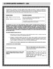
..., and/or Install _ product, instruct, or replace house fu_ or correct wiring, or correct.on all parts [_[uding the Drum Tub and Motor, THBWA_ iS ...problems that result from the menu, and have product ty_ (Dryer), model number, serial number, and ZiP code reac_y. Friday, 7 N_ ~ 8 _ CT; LGWILLNOTBEUAB_ F_ ANY _ENTIAL INDI_CT, _ INCIDENTALDAMAGESOF ANY KIND,INCLUDINGLCSTREVENUE_S PROFITS|N, _NNECTION WITHTHE_D_. _E STA_ _ NOTALLOWLIMITATION_ HOW LONGAN IM_JEDWARRANTY LASTSORTHEEXCLUSIONOFINCIDENTAOL R_ENTIAL MAY NOTAPPLYTOY_J. LG Electronics Inc, will repair or at its option replace...
..., and/or Install _ product, instruct, or replace house fu_ or correct wiring, or correct.on all parts [_[uding the Drum Tub and Motor, THBWA_ iS ...problems that result from the menu, and have product ty_ (Dryer), model number, serial number, and ZiP code reac_y. Friday, 7 N_ ~ 8 _ CT; LGWILLNOTBEUAB_ F_ ANY _ENTIAL INDI_CT, _ INCIDENTALDAMAGESOF ANY KIND,INCLUDINGLCSTREVENUE_S PROFITS|N, _NNECTION WITHTHE_D_. _E STA_ _ NOTALLOWLIMITATION_ HOW LONGAN IM_JEDWARRANTY LASTSORTHEEXCLUSIONOFINCIDENTAOL R_ENTIAL MAY NOTAPPLYTOY_J. LG Electronics Inc, will repair or at its option replace...
Service Manual
Page 4
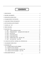
...SPECIFICATIONS ...4 2. TEST 6 HEATER SWITCH TEST - EXPLODED VIEW ...32 12-1. TEST 4 MOISTURE SENSOR 20 9-5. ELECTRIC TYPE 22 9-7. CABINET & DOOR ASSEMBLY 33 12-3-1. TEST 1 120VAC ELECTRICAL SUPPLY 17 9-2. DISASSEMBLY INSTRUCTIONS 26 12. DRUM & MOTOR ASSEMBLY : ELECTRIC TYPE 34 12-3-2. COMPONENT TESTING INFORMATION 10 6. WIRING DIAGRAM ...15 9. TEST 7 GAS VALVE TEST - GAS TYPE 23 10. REPLACEMENT PARTS LIST 36 3 TEST 5 DOOR SWITCH TEST 21 9-6. CONTENTS 1. INSTALLATION INSTRUCTIONS 6 4. CONTROL LAY - MOTOR DIAGRAM AND SCHEMATIC 13 7. TEST 2 THERMISTOR...
...SPECIFICATIONS ...4 2. TEST 6 HEATER SWITCH TEST - EXPLODED VIEW ...32 12-1. TEST 4 MOISTURE SENSOR 20 9-5. ELECTRIC TYPE 22 9-7. CABINET & DOOR ASSEMBLY 33 12-3-1. TEST 1 120VAC ELECTRICAL SUPPLY 17 9-2. DISASSEMBLY INSTRUCTIONS 26 12. DRUM & MOTOR ASSEMBLY : ELECTRIC TYPE 34 12-3-2. COMPONENT TESTING INFORMATION 10 6. WIRING DIAGRAM ...15 9. TEST 7 GAS VALVE TEST - GAS TYPE 23 10. REPLACEMENT PARTS LIST 36 3 TEST 5 DOOR SWITCH TEST 21 9-6. CONTENTS 1. INSTALLATION INSTRUCTIONS 6 4. CONTROL LAY - MOTOR DIAGRAM AND SCHEMATIC 13 7. TEST 2 THERMISTOR...
Service Manual
Page 7
...silver-colored terminal block screw 5. Insert tab of terminal block cover into slot of dryer rear panel Secure cover with upturned ends 6. 3/4 in . (1.9 cm) UL-listed strain relief 4. Tighten screws. 6. Connect ground wire (green or bare) of the terminal block. 1 2 6 34 5 7 1. 4-wire receptacle (NEMA type 14-30R) 2. 4-prong plug 3. Remove center terminal block screw. 2. Remove appliance ground wire (green) from external ground connector screw. Center silver-colored terminal block screw 3. Ring terminals 1. External ground connector 2. Connect the other wires to...
...silver-colored terminal block screw 5. Insert tab of terminal block cover into slot of dryer rear panel Secure cover with upturned ends 6. 3/4 in . (1.9 cm) UL-listed strain relief 4. Tighten screws. 6. Connect ground wire (green or bare) of the terminal block. 1 2 6 34 5 7 1. 4-wire receptacle (NEMA type 14-30R) 2. 4-prong plug 3. Remove center terminal block screw. 2. Remove appliance ground wire (green) from external ground connector screw. Center silver-colored terminal block screw 3. Ring terminals 1. External ground connector 2. Connect the other wires to...
Service Manual
Page 16
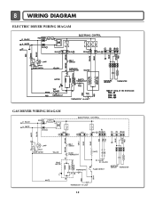
8 WIRING DIAGRAM ELECTRIC DRYER WIRING DIAGAM GAS DRYER WIRING DIAGAM 15
8 WIRING DIAGRAM ELECTRIC DRYER WIRING DIAGAM GAS DRYER WIRING DIAGAM 15
Service Manual
Page 17
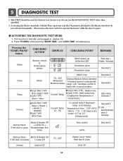
... TIME", and "LESS TIME" simultaneously. Pressing the "START/PAUSE" button CHECKING ACTION DISPLAY CHECKING POINT REMARK None Electric control & Temperature sensor Won't power up Defective LED Thermistor open ) ACTIVATING THE DIAGNOSTIC TEST MODE 1. Do not use this DIAGNOSTIC TEST other than specified. 2. Temperature in 4min : 113°F (45°C) • Above : 1" on , 1" off beep sound • Under : 0.5" on, 0.5" off ) 2. Displays Moisture Sensor Operation: If moisture sensor is contacted with the Door open may...
... TIME", and "LESS TIME" simultaneously. Pressing the "START/PAUSE" button CHECKING ACTION DISPLAY CHECKING POINT REMARK None Electric control & Temperature sensor Won't power up Defective LED Thermistor open ) ACTIVATING THE DIAGNOSTIC TEST MODE 1. Do not use this DIAGNOSTIC TEST other than specified. 2. Temperature in 4min : 113°F (45°C) • Above : 1" on , 1" off beep sound • Under : 0.5" on, 0.5" off ) 2. Displays Moisture Sensor Operation: If moisture sensor is contacted with the Door open may...
Service Manual
Page 20
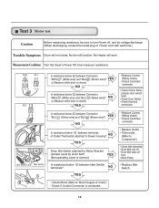
...Motor Diagram & Check') • Check if Control Connector is closed . Measurement Condition Turn the Dryer's Power Off, then measure resistance. NO YES Does Idle Switch attached to turn Power off from • Motor Pulley. • Replace Idler Switch. • Check Motor.(Refer to blower housing? " (Yellow wire)? YES (Not operating Lever is closed . YES • Replace Control. (Relay check) • Check Controller connector. • Check if Door flame presses door switch knob. • Check Door Switch. • Check Harness connection. No fan will work. Test 3 Motor test...
...Motor Diagram & Check') • Check if Control Connector is closed . Measurement Condition Turn the Dryer's Power Off, then measure resistance. NO YES Does Idle Switch attached to turn Power off from • Motor Pulley. • Replace Idler Switch. • Check Motor.(Refer to blower housing? " (Yellow wire)? YES (Not operating Lever is closed . YES • Replace Control. (Relay check) • Check Controller connector. • Check if Door flame presses door switch knob. • Check Door Switch. • Check Harness connection. No fan will work. Test 3 Motor test...

Service Manual
Page 21
YES • Replace Control and Check. Test 4 Moisture sensor Caution Before measuring resistance, be sure to turn Power off, and do voltage discharge. (When discharging, contact the metal plug of Power cord with earth line.) Trouble Symptom Degree of Table 2 NO when measuring the voltage in Electric load, is resistance below 1Ω? IMC Ratio and Display Value / Voltage (IMC : Initial Moisture Content) IMC 70% ~ 40...
YES • Replace Control and Check. Test 4 Moisture sensor Caution Before measuring resistance, be sure to turn Power off, and do voltage discharge. (When discharging, contact the metal plug of Power cord with earth line.) Trouble Symptom Degree of Table 2 NO when measuring the voltage in Electric load, is resistance below 1Ω? IMC Ratio and Display Value / Voltage (IMC : Initial Moisture Content) IMC 70% ~ 40...


