Specification (English)
Page 2
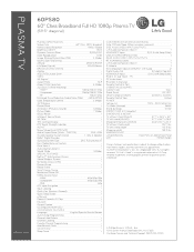
...Component 1080p/1080i/720p - Component 60p/30p/24p - PC 1 PC Audio Input 1 RS-232c In (Service) 1 Remote Control In Port 1 CABINET/ACCESSORIES Cabinet Color Glass Stand Swivel 20º/20º VESA® Compliant (WxH) 600mm x 400mm Remote Control ... (D-Sub 15pin) - All rights reserved. PLASMA TV 60PS80 60" Class Broadband Full HD 1080p Plasma TV (59.5" diagonal) LGusa.com PLASMA SPECIFICATION Screen Size 60" Class (59.5" diagonal) Native Display Resolution 1920 x 1080p Brightness (cd/m2) 1,500 Dynamic Contrast ...
...Component 1080p/1080i/720p - Component 60p/30p/24p - PC 1 PC Audio Input 1 RS-232c In (Service) 1 Remote Control In Port 1 CABINET/ACCESSORIES Cabinet Color Glass Stand Swivel 20º/20º VESA® Compliant (WxH) 600mm x 400mm Remote Control ... (D-Sub 15pin) - All rights reserved. PLASMA TV 60PS80 60" Class Broadband Full HD 1080p Plasma TV (59.5" diagonal) LGusa.com PLASMA SPECIFICATION Screen Size 60" Class (59.5" diagonal) Native Display Resolution 1920 x 1080p Brightness (cd/m2) 1,500 Dynamic Contrast ...
Owner's Manual (English)
Page 6
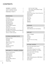
... (Manual Tuning 56 - TV Widgets 70 Netflix 78 My Media 90 YouTube 108 NETCAST Time-Out Setting 111 Vudu 112 PICTURE CONTROL Picture Size (Aspect Ratio) Control 128 Picture Wizard 130 Preset Picture Settings (Picture Mode 132 Manual Picture Adjustment - CONTENTS WARNING / CAUTION 2 SAFETY INSTRUCTIONS 3...Other A/V Source Setup 36 USB Connection 36 PC Setup 37 Audio out Connection 44 Network Setup 45 WATCHING TV / CHANNEL CONTROL Remote Control Functions 48 Turning On the TV 50 Channel Selection 50 Volume Adjustment 50 Initial Setting 51 On-Screen Menus Selection 53 ...
... (Manual Tuning 56 - TV Widgets 70 Netflix 78 My Media 90 YouTube 108 NETCAST Time-Out Setting 111 Vudu 112 PICTURE CONTROL Picture Size (Aspect Ratio) Control 128 Picture Wizard 130 Preset Picture Settings (Picture Mode 132 Manual Picture Adjustment - CONTENTS WARNING / CAUTION 2 SAFETY INSTRUCTIONS 3...Other A/V Source Setup 36 USB Connection 36 PC Setup 37 Audio out Connection 44 Network Setup 45 WATCHING TV / CHANNEL CONTROL Remote Control Functions 48 Turning On the TV 50 Channel Selection 50 Volume Adjustment 50 Initial Setting 51 On-Screen Menus Selection 53 ...
Owner's Manual (English)
Page 9
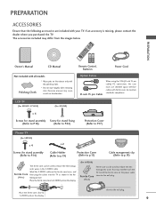
... (Refer to P.17) Plasma TV (For 50PS80) x 4 x 2 Screws for stand assembly (Refer to P.14) Cable Holder (Refer to p.19) Protection Cover (Refer to p.15) Cable management clip (Refer to p.19) The ferrite core can be used to the wall plug. 9 netic waves in the fol- (White) lowing picture. Remote Control, Batteries Power Cord...
... (Refer to P.17) Plasma TV (For 50PS80) x 4 x 2 Screws for stand assembly (Refer to P.14) Cable Holder (Refer to p.19) Protection Cover (Refer to p.15) Cable management clip (Refer to p.19) The ferrite core can be used to the wall plug. 9 netic waves in the fol- (White) lowing picture. Remote Control, Batteries Power Cord...
Owner's Manual (English)
Page 10
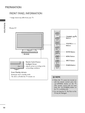
... work when the (POWER) button on . The floor or the TV may differ from your TV. NOTE G When the TV cannot be damaged. 10 Plasma TV SPEAKER Remote Control Sensor, Intelligent Sensor Adjusts picture according to the surrounding conditions Power/Standby Indicator Illuminates red in standby mode. G Do not drag the TV. The...
... work when the (POWER) button on . The floor or the TV may differ from your TV. NOTE G When the TV cannot be damaged. 10 Plasma TV SPEAKER Remote Control Sensor, Intelligent Sensor Adjusts picture according to the surrounding conditions Power/Standby Indicator Illuminates red in standby mode. G Do not drag the TV. The...
Owner's Manual (English)
Page 11
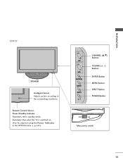
G p.141) CH VOL ENTER MENU INPUT CHANNEL (D,E) Buttons VOLUME (+, -) Buttons ENTER Button MENU Button INPUT Button POWER Button OFF ON Main power switch 11 PREPARATION LCD TV SPEAKER Intelligent Sensor Adjusts picture according to the surrounding conditions Remote Control Sensor, Power/Standby Indicator Illuminates red in the OPTION menu. Illuminates blue when the TV is switched on. (Can be adjusted using the Power Indicator in standby mode.
G p.141) CH VOL ENTER MENU INPUT CHANNEL (D,E) Buttons VOLUME (+, -) Buttons ENTER Button MENU Button INPUT Button POWER Button OFF ON Main power switch 11 PREPARATION LCD TV SPEAKER Intelligent Sensor Adjusts picture according to the surrounding conditions Remote Control Sensor, Power/Standby Indicator Illuminates red in the OPTION menu. Illuminates blue when the TV is switched on. (Can be adjusted using the Power Indicator in standby mode.

Owner's Manual (English)
Page 13
... an adapter or HDMI to this jack. 7 SERVICE ONLY PORT This port is used for use with amps and home theater systems. 11 REMOTE CONTROL IN PORT For a wired remote control. 12 Power Cord Socket For operation with amps and home theater systems. Note: In standby mode, this port doesn't work. 6 ANTENNA/CABLE IN...
... an adapter or HDMI to this jack. 7 SERVICE ONLY PORT This port is used for use with amps and home theater systems. 11 REMOTE CONTROL IN PORT For a wired remote control. 12 Power Cord Socket For operation with amps and home theater systems. Note: In standby mode, this port doesn't work. 6 ANTENNA/CABLE IN...
Owner's Manual (English)
Page 25
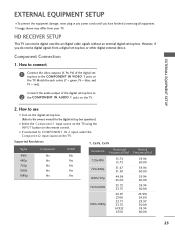
... the TV. Match the jack colors (Y = green, PB = blue, and PR = red). Supported Resolutions Y, CB/PB, CR/PR Signal 480i 480p 720p 1080i 1080p Component Yes Yes Yes Yes Yes HDMI No Yes Yes Yes Yes Resolution Horizontal Frequency(KHz) 720x480i 720x480p 1280x720p 15.73 15.73 31.47....00 25 How to use I Turn on the digital set-top box. (Refer to COMPONENT IN 2 input, select the Component2 input source on the remote control. I Select the Component1 input source on the TV using the INPUT button on the TV. Component Connection 1. I To prevent the equipment damage, never ...
... the TV. Match the jack colors (Y = green, PB = blue, and PR = red). Supported Resolutions Y, CB/PB, CR/PR Signal 480i 480p 720p 1080i 1080p Component Yes Yes Yes Yes Yes HDMI No Yes Yes Yes Yes Resolution Horizontal Frequency(KHz) 720x480i 720x480p 1280x720p 15.73 15.73 31.47....00 25 How to use I Turn on the digital set-top box. (Refer to COMPONENT IN 2 input, select the Component2 input source on the remote control. I Select the Component1 input source on the TV using the INPUT button on the TV. Component Connection 1. I To prevent the equipment damage, never ...
Owner's Manual (English)
Page 27
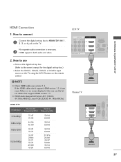
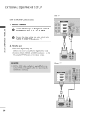
...digital set-top box. (Refer to the owner's manual for the digital set -top box to HDMI/DVI IN 1, 2, 3, or 4 jack on the remote control. ! G HDMI Audio Supported Format: AC3 (32KHz, 44.1KHz,48KHz), Linear PCM (32KHz, 44.1KHz,48KHz) HDMI-DTV Resolution Horizontal Vertical Frequency(KHz) ...L(MONO) AUDIO R 3 2 L R 1 EO AUDIO OMPONENT IN /DVI IN RGB IN (PC) AUDIO IN OPT A (RGB/DVI) AN SERVICE ONLY CA () 1 HDMI OUTPUT Plasma TV ( ) 3 2 1 AU (R OPTICAL DIGITAL /DVI IN AUDIO OUT RGB IN (PC) R AUDIO L(MONO) VIDEO S-VIDEO LAN SERVICE AV ONLY 1 HDMI OUTPUT 27 How to...
...digital set-top box. (Refer to the owner's manual for the digital set -top box to HDMI/DVI IN 1, 2, 3, or 4 jack on the remote control. ! G HDMI Audio Supported Format: AC3 (32KHz, 44.1KHz,48KHz), Linear PCM (32KHz, 44.1KHz,48KHz) HDMI-DTV Resolution Horizontal Vertical Frequency(KHz) ...L(MONO) AUDIO R 3 2 L R 1 EO AUDIO OMPONENT IN /DVI IN RGB IN (PC) AUDIO IN OPT A (RGB/DVI) AN SERVICE ONLY CA () 1 HDMI OUTPUT Plasma TV ( ) 3 2 1 AU (R OPTICAL DIGITAL /DVI IN AUDIO OUT RGB IN (PC) R AUDIO L(MONO) VIDEO S-VIDEO LAN SERVICE AV ONLY 1 HDMI OUTPUT 27 How to...
Owner's Manual (English)
Page 28
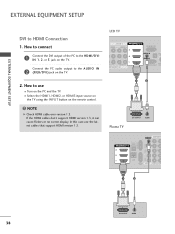
...) AUDIO R 3 2 L R 1 AUDIO NT IN () /DVI IN RGB IN (PC) AUDIO IN (RGB/DVI) OPTICAL DIGITA AUDIO OUT ANTENNA/ SERVICE ONLY CABLE IN 1 2 DVI OUTPUT L R AUDIO Plasma TV PR RGB IN (PC) R AUDIO L(MONO) VIDEO S-VIDEO OPTICAL DIGITAL /DVI IN AUDIO OUT 3 AUDIO IN COMPONENT (RGB/DVI) PB Y L 2 R 1 LAN SERVICE AV IN... on the TV. 2. How to connect 1 Connect the DVI output of the digital set-top box to the AUDIO IN (RGB/DVI) jack on the remote control. !
...) AUDIO R 3 2 L R 1 AUDIO NT IN () /DVI IN RGB IN (PC) AUDIO IN (RGB/DVI) OPTICAL DIGITA AUDIO OUT ANTENNA/ SERVICE ONLY CABLE IN 1 2 DVI OUTPUT L R AUDIO Plasma TV PR RGB IN (PC) R AUDIO L(MONO) VIDEO S-VIDEO OPTICAL DIGITAL /DVI IN AUDIO OUT 3 AUDIO IN COMPONENT (RGB/DVI) PB Y L 2 R 1 LAN SERVICE AV IN... on the TV. 2. How to connect 1 Connect the DVI output of the digital set-top box to the AUDIO IN (RGB/DVI) jack on the remote control. !
Owner's Manual (English)
Page 29
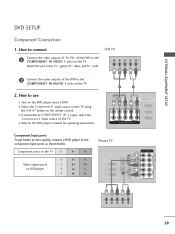
I Select the Component1 input source on the TV using the INPUT button on DVD player Y PB PR Y B-Y R-Y Y Cb Cr Y Pb Pr Plasma TV ( ) AUDIO IN COMPONENT IN (RGB/DVI) Y VIDEO RGB IN (PC) R AUDIO L(MONO) VIDEO S-VIDEO PB OPTICAL DIGITAL /DVI IN AUDIO OUT 3 PR RE 2... blue, and PR = red). How to the component input ports as shown below. Component ports on the TV Y PB PR Video output ports on the remote control. EXTERNAL EQUIPMENT SETUP DVD SETUP Component Connection 1. How to connect 1 Connect the video outputs (Y, PB, PR) of the DVD to the COMPONENT IN VIDEO ...
I Select the Component1 input source on the TV using the INPUT button on DVD player Y PB PR Y B-Y R-Y Y Cb Cr Y Pb Pr Plasma TV ( ) AUDIO IN COMPONENT IN (RGB/DVI) Y VIDEO RGB IN (PC) R AUDIO L(MONO) VIDEO S-VIDEO PB OPTICAL DIGITAL /DVI IN AUDIO OUT 3 PR RE 2... blue, and PR = red). How to the component input ports as shown below. Component ports on the TV Y PB PR Video output ports on the remote control. EXTERNAL EQUIPMENT SETUP DVD SETUP Component Connection 1. How to connect 1 Connect the video outputs (Y, PB, PR) of the DVD to the COMPONENT IN VIDEO ...
Owner's Manual (English)
Page 30
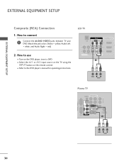
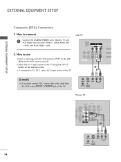
... ( ) EXTERNAL EQUIPMENT SETUP Composite (RCA) Connection 1. I Turn on the remote control. LCD TV AV IN 1 LAN VIDEO L(MONO) AUDIO R 3 2 2 L R 1 1 VIDEO AUDIO COMPONENT IN () 1 /DVI IN A ( VIDEO L R AUDIO Plasma TV AUDIO OUT ( ) AUDIO IN COMPONENT IN (RGB/DVI) L UT... R Y VIDEO PB L PR RGB IN (PC) R AUDIO L(MONO) VIDEO S-VIDEO SERVICE AV IN 1 1 ONLY R L AUDIO REMOTE CONTROL IN ANTENNA/ CABLE IN 2 1 VIDEO L R AUDIO 30 () How to...
... ( ) EXTERNAL EQUIPMENT SETUP Composite (RCA) Connection 1. I Turn on the remote control. LCD TV AV IN 1 LAN VIDEO L(MONO) AUDIO R 3 2 2 L R 1 1 VIDEO AUDIO COMPONENT IN () 1 /DVI IN A ( VIDEO L R AUDIO Plasma TV AUDIO OUT ( ) AUDIO IN COMPONENT IN (RGB/DVI) L UT... R Y VIDEO PB L PR RGB IN (PC) R AUDIO L(MONO) VIDEO S-VIDEO SERVICE AV IN 1 1 ONLY R L AUDIO REMOTE CONTROL IN ANTENNA/ CABLE IN 2 1 VIDEO L R AUDIO 30 () How to...
Owner's Manual (English)
Page 31
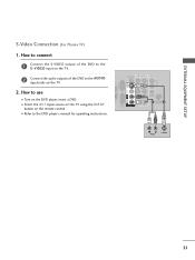
How to use I Select the A V 1 input source on the TV using the INPUT button on the remote control. () EXTERNAL EQUIPMENT SETUP S-Video Connection (For Plasma TV) 1. I Turn on the TV. () 2. AUDIO OUT Y R AUDIO IN COMPONENT IN (RGB/DVI) AL AL OUT VIDEO PB L PR ...RGB IN (PC) R AUDIO L(MONO) VIDEO S-VIDEO N SERVICE AV IN 1 1 ONLY R L AUDIO REMOTE CONTROL IN 1 ACNATBELNENIAN/2 2 L R AUDIO S-VIDEO () 31...
How to use I Select the A V 1 input source on the TV using the INPUT button on the remote control. () EXTERNAL EQUIPMENT SETUP S-Video Connection (For Plasma TV) 1. I Turn on the TV. () 2. AUDIO OUT Y R AUDIO IN COMPONENT IN (RGB/DVI) AL AL OUT VIDEO PB L PR ...RGB IN (PC) R AUDIO L(MONO) VIDEO S-VIDEO N SERVICE AV IN 1 1 ONLY R L AUDIO REMOTE CONTROL IN 1 ACNATBELNENIAN/2 2 L R AUDIO S-VIDEO () 31...
Owner's Manual (English)
Page 32
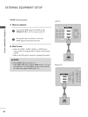
...) AUDIO R 3 2 L R 1 O AUDIO MPONENT IN /DVI IN RGB IN (PC) AUDIO IN (RGB/DVI) OPTIC AU ANT SERVICE ONLY CAB () 1 HDMI OUTPUT Plasma TV RGB IN (PC) R AUDIO L(MONO) VIDEO S-VIDEO OPTICAL DIGITAL /DVI IN AUDIO OUT 3 AUDIO IN COM (RGB/DVI) 2 1 LAN SERVICE AV IN 1 1 ONLY... is necessary. How to connect 1 Connect the HDMI output of the DVD to the HDMI/DVI IN 1, 2, 3 or 4 jack on the remote control. If the HDMI cables don't support HDMI version 1.3, it can cause flickers or no screen display. () EXTERNAL EQUIPMENT SETUP EXTERNAL EQUIPMENT SETUP HDMI Connection...
...) AUDIO R 3 2 L R 1 O AUDIO MPONENT IN /DVI IN RGB IN (PC) AUDIO IN (RGB/DVI) OPTIC AU ANT SERVICE ONLY CAB () 1 HDMI OUTPUT Plasma TV RGB IN (PC) R AUDIO L(MONO) VIDEO S-VIDEO OPTICAL DIGITAL /DVI IN AUDIO OUT 3 AUDIO IN COM (RGB/DVI) 2 1 LAN SERVICE AV IN 1 1 ONLY... is necessary. How to connect 1 Connect the HDMI output of the DVD to the HDMI/DVI IN 1, 2, 3 or 4 jack on the remote control. If the HDMI cables don't support HDMI version 1.3, it can cause flickers or no screen display. () EXTERNAL EQUIPMENT SETUP EXTERNAL EQUIPMENT SETUP HDMI Connection...
Owner's Manual (English)
Page 33
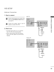
... on the TV. I Set VCR output switch to 3 or 4 and then tune TV to the VCR owner's manual.) Plasma TV ANT OUT S-VIDEO VIDEO L R AUDIO ANT IN OUTPUT SWITCH Wall Jack 2 Antenna VIDEO L AUDIO O () REMOTE CONTROL IN 1 AUDIO ANTENNA/ CABLE IN ANT OUT S-VIDEO VIDEO L R AUDIO 2 ANT IN OUTPUT SWITCH Wall Jack 2 Antenna...
... on the TV. I Set VCR output switch to 3 or 4 and then tune TV to the VCR owner's manual.) Plasma TV ANT OUT S-VIDEO VIDEO L R AUDIO ANT IN OUTPUT SWITCH Wall Jack 2 Antenna VIDEO L AUDIO O () REMOTE CONTROL IN 1 AUDIO ANTENNA/ CABLE IN ANT OUT S-VIDEO VIDEO L R AUDIO 2 ANT IN OUTPUT SWITCH Wall Jack 2 Antenna...
Owner's Manual (English)
Page 34
....) I 2. ANT IN S-VIDEO VIDEO L R AUDIO ANT OUT OUTPUT SWITCH Plasma TV AUDIO OUT CAL TAL O OUT ( ) AUDIO IN COMPONENT IN (RGB/DVI) PB Y R VIDEO L PR RGB IN (PC) R AUDIO L(MONO) VIDEO S-VIDEO AN SERVICE AV IN 1 1 ONLY R L AUDIO REMOTE CONTROL IN ANTENNA/ CABLE IN 2 1 34 ANT IN S-VIDEO VIDEO L R AUDIO... use I Insert a video tape into the VCR and press PLAY on the VCR. (Refer to AV IN 2, select AV2 input source on the remote control. NOTE G If you have a mono VCR, connect the audio cable from the VCR to connect LCD TV 1 Connect the AUDIO/VIDEO jacks between TV...
....) I 2. ANT IN S-VIDEO VIDEO L R AUDIO ANT OUT OUTPUT SWITCH Plasma TV AUDIO OUT CAL TAL O OUT ( ) AUDIO IN COMPONENT IN (RGB/DVI) PB Y R VIDEO L PR RGB IN (PC) R AUDIO L(MONO) VIDEO S-VIDEO AN SERVICE AV IN 1 1 ONLY R L AUDIO REMOTE CONTROL IN ANTENNA/ CABLE IN 2 1 34 ANT IN S-VIDEO VIDEO L R AUDIO... use I Insert a video tape into the VCR and press PLAY on the VCR. (Refer to AV IN 2, select AV2 input source on the remote control. NOTE G If you have a mono VCR, connect the audio cable from the VCR to connect LCD TV 1 Connect the AUDIO/VIDEO jacks between TV...

Owner's Manual (English)
Page 35
...the VCR owner's manual.) I Insert a video tape into the VCR and press PLAY on the VCR. (Refer to the AUDIO input jacks on the remote control. In the event that you connect both Video and S-Video at the same time. ANT IN VIDEO L R AUDIO ANT OUT S-VIDEO OUTPUT SWITCH ...IGITAL DIO OUT AUDIO IN COMPONENT IN (RGB/DVI) PB Y VIDEO L PR RGB IN (PC) R AUDIO L(MONO) VIDEO S-VIDEO LAN SERVICE AV IN 1 1 ONLY R L REMOTE CONTROL IN AUDIO ANTENNA/ CABLE IN 2 1 2 ! How to use I Select the A V 1 input source on the TV using the INPUT button on the TV. () 2. EXTERNAL EQUIPMENT...
...the VCR owner's manual.) I Insert a video tape into the VCR and press PLAY on the VCR. (Refer to the AUDIO input jacks on the remote control. In the event that you connect both Video and S-Video at the same time. ANT IN VIDEO L R AUDIO ANT OUT S-VIDEO OUTPUT SWITCH ...IGITAL DIO OUT AUDIO IN COMPONENT IN (RGB/DVI) PB Y VIDEO L PR RGB IN (PC) R AUDIO L(MONO) VIDEO S-VIDEO LAN SERVICE AV IN 1 1 ONLY R L REMOTE CONTROL IN AUDIO ANTENNA/ CABLE IN 2 1 2 ! How to use I Select the A V 1 input source on the TV using the INPUT button on the TV. () 2. EXTERNAL EQUIPMENT...
Owner's Manual (English)
Page 36
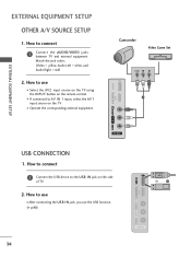
EXTERNAL EQUIPMENT SETUP OTHER A/V SOURCE SETUP 1. I Select the A V 2 input source on the TV using the INPUT button on the remote control. How to use I After connecting the USB I N jack, you use I If connected to the USB I Operate the corresponding external equipment. Match the jack colors. (Video = ...
EXTERNAL EQUIPMENT SETUP OTHER A/V SOURCE SETUP 1. I Select the A V 2 input source on the TV using the INPUT button on the remote control. How to use I After connecting the USB I N jack, you use I If connected to the USB I Operate the corresponding external equipment. Match the jack colors. (Video = ...
Owner's Manual (English)
Page 37
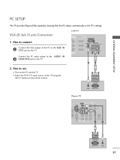
... RGB-PC input source on the TV using the INPUT button on the remote control. I Turn on the PC and the TV. VGA (D-Sub 15 pin) Connection 1. How to the RGB IN (P C) jack on the TV. AUDIO RGB OUTPUT Plasma TV AUDIO OUT R ( ) PTICAL IGITAL DIO OUT AUDIO IN COMPONENT IN... (RGB/DVI) PB Y VIDEO L PR RGB IN (PC) R AUDIO L(MONO) VIDEO S-VIDEO LAN SERVICE AV IN 1 1 ONLY R L REMOTE CONTROL IN AUDIO ANTENNA/ CABLE IN 2 1 2 RGB OUTPUT AUDIO 37...
... RGB-PC input source on the TV using the INPUT button on the remote control. I Turn on the PC and the TV. VGA (D-Sub 15 pin) Connection 1. How to the RGB IN (P C) jack on the TV. AUDIO RGB OUTPUT Plasma TV AUDIO OUT R ( ) PTICAL IGITAL DIO OUT AUDIO IN COMPONENT IN... (RGB/DVI) PB Y VIDEO L PR RGB IN (PC) R AUDIO L(MONO) VIDEO S-VIDEO LAN SERVICE AV IN 1 1 ONLY R L REMOTE CONTROL IN AUDIO ANTENNA/ CABLE IN 2 1 2 RGB OUTPUT AUDIO 37...
Owner's Manual (English)
Page 38
... using the INPUT button on the PC and the TV. I Turn on the remote control. ! LCD TV AV IN 1 VIDEO L(MONO) AUDIO R 3 2 L R 1 O AUDIO MPONENT IN () /DVI IN RGB IN (PC) AUDIO IN (RGB/DVI) OPTI AU ANT SERVICE ONLY CA 1 2 Plasma TV DVI OUTPUT AUDIO PR RGB IN (PC) R AUDIO L(MONO) VIDEO S-VIDEO...
... using the INPUT button on the PC and the TV. I Turn on the remote control. ! LCD TV AV IN 1 VIDEO L(MONO) AUDIO R 3 2 L R 1 O AUDIO MPONENT IN () /DVI IN RGB IN (PC) AUDIO IN (RGB/DVI) OPTI AU ANT SERVICE ONLY CA 1 2 Plasma TV DVI OUTPUT AUDIO PR RGB IN (PC) R AUDIO L(MONO) VIDEO S-VIDEO...
Owner's Manual (English)
Page 44
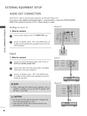
... the laser beam may block digital audio output. G Audio with external audio equipment, such as amplifiers or speakers, you want to a Home Theater (or amp). Plasma TV 3 2 1 RGB IN (PC) R AUDIO L(MONO) VIDEO S-VIDEO OPTICAL DIGITAL /DVI IN AUDIO OUT PB PR L 1 R LAN SERVICE AV IN ...Protection) function may damage your vision. Plasma TV AUDIO OUT R OPTICAL DIGITAL VI IN AUDIO OUT AUDIO IN COMPONENT IN (RGB/DVI) PB Y VIDEO L PR RGB IN (PC) R AUDIO L(MONO) VIDEO S-VIDEO 1 LAN SERVICE AV IN 1 1 ONLY R L AUDIO REMOTE CONTROL IN ANTENNA/ CABLE IN 2 EXTERNAL EQUIPMENT...
... the laser beam may block digital audio output. G Audio with external audio equipment, such as amplifiers or speakers, you want to a Home Theater (or amp). Plasma TV 3 2 1 RGB IN (PC) R AUDIO L(MONO) VIDEO S-VIDEO OPTICAL DIGITAL /DVI IN AUDIO OUT PB PR L 1 R LAN SERVICE AV IN ...Protection) function may damage your vision. Plasma TV AUDIO OUT R OPTICAL DIGITAL VI IN AUDIO OUT AUDIO IN COMPONENT IN (RGB/DVI) PB Y VIDEO L PR RGB IN (PC) R AUDIO L(MONO) VIDEO S-VIDEO 1 LAN SERVICE AV IN 1 1 ONLY R L AUDIO REMOTE CONTROL IN ANTENNA/ CABLE IN 2 EXTERNAL EQUIPMENT...

