Owner's Manual
Page 6
... Picture Settings(Picture Mode 69 Manual Picture Adjustment - Auto Scan (Auto Tuning 43 - User Mode 70 Picture Improvement Technology 71 Expert Picture Control 72 Picture Reset 74 Demo Mode 74 Image Sticking Minimization (ISM) Method 75 6 CONTENTS WARNING / CAUTION 2 SAFETY INSTRUCTIONS 3 FEATURE OF...VCR Setup 27 Other A/V Source Setup 28 USB Connection 28 Audio Out Connection 29 PC Setup 30 WATCHING TV / CHANNEL CONTROL Remote Control Functions 36 Turning On TV 38 Channel Selection 38 Volume Adjustment 38 Initial Setting 39 On-Screen Menus Selection 40 Quick Menu ...
... Picture Settings(Picture Mode 69 Manual Picture Adjustment - Auto Scan (Auto Tuning 43 - User Mode 70 Picture Improvement Technology 71 Expert Picture Control 72 Picture Reset 74 Demo Mode 74 Image Sticking Minimization (ISM) Method 75 6 CONTENTS WARNING / CAUTION 2 SAFETY INSTRUCTIONS 3 FEATURE OF...VCR Setup 27 Other A/V Source Setup 28 USB Connection 28 Audio Out Connection 29 PC Setup 30 WATCHING TV / CHANNEL CONTROL Remote Control Functions 36 Turning On TV 38 Channel Selection 38 Volume Adjustment 38 Initial Setting 39 On-Screen Menus Selection 40 Quick Menu ...
Owner's Manual
Page 9
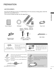
... EXIT FREEZE Q.MENU or 753 86 LIST 0 9 MENU VOL FAVMARK MUTERATIO CH FLASHBK INFO P A G E ENTER Q.MENU BACK 1.5V 1.5V EXIT FREEZE Owner's Manual CD Manual Remote Control, Batteries (Except 60PK250, 60PK540, 60PK550, 60PK280, 60PK290, 60PK550C) Power Cord Protection Cover (Refer to P.16) x 4 x 3 M4x28 M5x14 Bolts for stand assembly (Refer to P.15) x 2 Cable...
... EXIT FREEZE Q.MENU or 753 86 LIST 0 9 MENU VOL FAVMARK MUTERATIO CH FLASHBK INFO P A G E ENTER Q.MENU BACK 1.5V 1.5V EXIT FREEZE Owner's Manual CD Manual Remote Control, Batteries (Except 60PK250, 60PK540, 60PK550, 60PK280, 60PK290, 60PK550C) Power Cord Protection Cover (Refer to P.16) x 4 x 3 M4x28 M5x14 Bolts for stand assembly (Refer to P.15) x 2 Cable...
Owner's Manual
Page 10
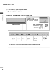
ENTER VOL CH Power/Standby Indicator Illuminates red in standby mode. The LED is off while the TV remains on. Remote Control Sensor ENTER VOL CH POWER INPUT Button Button MENU Button ENTER Button VOLUME Buttons CHANNEL Buttons ENTER You can operate the button just by touching the button lightly with your TV. 50/60PK550, 50/60PK540, 42/50PJ550, 50/60PK550C Intelligent Sensor Adjusts picture according to the surrounding conditions. PREPARATION PREPARATION FRONT PANEL INFORMATION I Image shown may differ from your finger. 10
ENTER VOL CH Power/Standby Indicator Illuminates red in standby mode. The LED is off while the TV remains on. Remote Control Sensor ENTER VOL CH POWER INPUT Button Button MENU Button ENTER Button VOLUME Buttons CHANNEL Buttons ENTER You can operate the button just by touching the button lightly with your TV. 50/60PK550, 50/60PK540, 42/50PJ550, 50/60PK550C Intelligent Sensor Adjusts picture according to the surrounding conditions. PREPARATION PREPARATION FRONT PANEL INFORMATION I Image shown may differ from your finger. 10

Owner's Manual
Page 11
PREPARATION 50/60PK250, 42/50PJ250, 60PK280, 60PK290 Intelligent Sensor Adjusts picture according to the surrounding conditions. ENTER VOL CH Power/Standby Indicator Illuminates red in standby mode. The LED is off while the TV remains on. Remote Control Sensor ENTER VOL CH POWER INPUT Button Button MENU Button ENTER Button VOLUME Buttons CHANNEL Buttons ENTER You can operate the button just by touching the button lightly with your finger. 11
PREPARATION 50/60PK250, 42/50PJ250, 60PK280, 60PK290 Intelligent Sensor Adjusts picture according to the surrounding conditions. ENTER VOL CH Power/Standby Indicator Illuminates red in standby mode. The LED is off while the TV remains on. Remote Control Sensor ENTER VOL CH POWER INPUT Button Button MENU Button ENTER Button VOLUME Buttons CHANNEL Buttons ENTER You can operate the button just by touching the button lightly with your finger. 11

Owner's Manual
Page 12
..., causing possible injury from fragments of glass, or the TV may be damaged. 12 ENTER VOL CH Power/Standby Indicator Illuminates red in standby mode. Remote Control Sensor ENTER VOL CH VOL POWER Button INPUT Button CH MENU Button ENTER Button VOLUME Buttons CHANNEL Buttons You can operate the button just by...
..., causing possible injury from fragments of glass, or the TV may be damaged. 12 ENTER VOL CH Power/Standby Indicator Illuminates red in standby mode. Remote Control Sensor ENTER VOL CH VOL POWER Button INPUT Button CH MENU Button ENTER Button VOLUME Buttons CHANNEL Buttons You can operate the button just by...
Owner's Manual
Page 13
... 50/60PK540, 50PK340 9 1 7 10 AV IN 2 2 4 5 7 OPTICAL DIGITAL AUDIO OUT AUDIO IN (RGB/DVI) REMOTE CONTROL IN AV IN 1 VIDEO /MONO AUDIO 1 () VARIABLE AUDIO OUT 2 1 HDMI/DVI IN 3 RS-232C IN (CONTROL & SERVICE) RGB IN (PC) 2 L R 1 VIDEO AUDIO COMPONENT IN 6 ANTENNA /CABLE 8 IN 1 HDMI/DVI IN... to this jack. 9 SERVICE ONLY Used for use with AC power. Uses a D-sub 15 pin cable (VGA cable). 5 REMOTE CONTROL IN PORT For a wired remote control. 6 COMPONENT IN Analog Connection. RGB IN (PC) Analog PC Connection. Supports standard definition video only (480i). 8 ANTENNA/CABLE...
... 50/60PK540, 50PK340 9 1 7 10 AV IN 2 2 4 5 7 OPTICAL DIGITAL AUDIO OUT AUDIO IN (RGB/DVI) REMOTE CONTROL IN AV IN 1 VIDEO /MONO AUDIO 1 () VARIABLE AUDIO OUT 2 1 HDMI/DVI IN 3 RS-232C IN (CONTROL & SERVICE) RGB IN (PC) 2 L R 1 VIDEO AUDIO COMPONENT IN 6 ANTENNA /CABLE 8 IN 1 HDMI/DVI IN... to this jack. 9 SERVICE ONLY Used for use with AC power. Uses a D-sub 15 pin cable (VGA cable). 5 REMOTE CONTROL IN PORT For a wired remote control. 6 COMPONENT IN Analog Connection. RGB IN (PC) Analog PC Connection. Supports standard definition video only (480i). 8 ANTENNA/CABLE...

Owner's Manual
Page 14
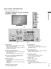
..., 50/60PK550C 9 1 PREPARATION 7 10 AV IN 2 2 4 5 7 OPTICAL DIGITAL AUDIO OUT AUDIO IN (RGB/DVI) REMOTE CONTROL IN AV IN 1 VIDEO /MONO AUDIO 1 () VARIABLE AUDIO OUT 2 1 HDMI/DVI IN 3 RS-232C IN (CONTROL & SERVICE) RGB IN (PC) 2 L R 1 VIDEO AUDIO COMPONENT IN 6 ANTENNA /CABLE 8 IN 1 HDMI/DVI IN...included) 2 OPTICAL DIGITAL AUDIO OUT Optical digital audio output for viewing photos and listening to this port doesn't work. 3 RS-232C IN (CONTROL & SERVICE) PORT Used by third party devices. Supports HD video and Digital audio. Uses a red, green, and blue cable for video...
..., 50/60PK550C 9 1 PREPARATION 7 10 AV IN 2 2 4 5 7 OPTICAL DIGITAL AUDIO OUT AUDIO IN (RGB/DVI) REMOTE CONTROL IN AV IN 1 VIDEO /MONO AUDIO 1 () VARIABLE AUDIO OUT 2 1 HDMI/DVI IN 3 RS-232C IN (CONTROL & SERVICE) RGB IN (PC) 2 L R 1 VIDEO AUDIO COMPONENT IN 6 ANTENNA /CABLE 8 IN 1 HDMI/DVI IN...included) 2 OPTICAL DIGITAL AUDIO OUT Optical digital audio output for viewing photos and listening to this port doesn't work. 3 RS-232C IN (CONTROL & SERVICE) PORT Used by third party devices. Supports HD video and Digital audio. Uses a red, green, and blue cable for video...
Owner's Manual
Page 22
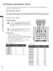
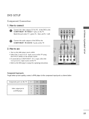
...receive digital signals from your TV. EXTERNAL EQUIPMENT SETUP Component Connection 1. How to the COMPONENT IN VIDEO 1 jacks on the TV. 1 2 O IN /DVI) REMOTE CONTROL IN AV IN 1 VIDEO /MONO AUDIO 2 L R 1 VIDEO AUDIO COMPONENT IN ANT CA Supported Resolutions Signal 480i 480p 720p 1080i 1080p Component Yes Yes Yes ... 30.00 59.939 60.00 23.94 29.97 22 I Select the Component1 input source on the TV using the INPUT button on the remote control. Y PB PR L R 2 Connect the audio output of the digital settop box to use I Image shown may differ from a digital set-top box...
...receive digital signals from your TV. EXTERNAL EQUIPMENT SETUP Component Connection 1. How to the COMPONENT IN VIDEO 1 jacks on the TV. 1 2 O IN /DVI) REMOTE CONTROL IN AV IN 1 VIDEO /MONO AUDIO 2 L R 1 VIDEO AUDIO COMPONENT IN ANT CA Supported Resolutions Signal 480i 480p 720p 1080i 1080p Component Yes Yes Yes ... 30.00 59.939 60.00 23.94 29.97 22 I Select the Component1 input source on the TV using the INPUT button on the remote control. Y PB PR L R 2 Connect the audio output of the digital settop box to use I Image shown may differ from a digital set-top box...
Owner's Manual
Page 23
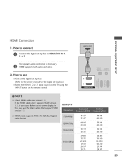
HDMI-DTV OUTPUT 1 OPTICAL DIGITAL AUDIO OUT AUDIO (RGB/DVI) 2 1 HDMI/DVI IN RS-232C IN (CONTROL & SERVICE) RGB IN(PC) ! NOTE G Check HDMI cable over version 1.3. EXTERNAL EQUIPMENT SETUP HDMI Connection 1. If the HDMI cables don't support HDMI version 1.3, it can ... format. How to connect 1 Connect the digital set -top box.) I Select the HDMI1, 2 or 3 input source on the TV using the INPUT button on the remote control. How to HDMI/DVI IN 1, 2 or 3 No separate audio connection is necessary. 2 HDMI supports both audio and video. 2.
HDMI-DTV OUTPUT 1 OPTICAL DIGITAL AUDIO OUT AUDIO (RGB/DVI) 2 1 HDMI/DVI IN RS-232C IN (CONTROL & SERVICE) RGB IN(PC) ! NOTE G Check HDMI cable over version 1.3. EXTERNAL EQUIPMENT SETUP HDMI Connection 1. If the HDMI cables don't support HDMI version 1.3, it can ... format. How to connect 1 Connect the digital set -top box.) I Select the HDMI1, 2 or 3 input source on the TV using the INPUT button on the remote control. How to HDMI/DVI IN 1, 2 or 3 No separate audio connection is necessary. 2 HDMI supports both audio and video. 2.
Owner's Manual
Page 24
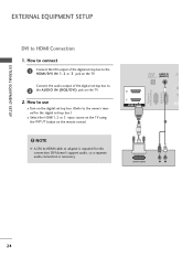
How to 2 the AUDIO IN (RGB/DVI) jack on the remote control. ! OPTICAL DIGITAL AUDIO OUT AUDIO IN (RGB/DVI) R CO RS-232C IN (CONTROL & SERVICE) RGB IN (PC) 2 2 1 1 HDMI/DVI IN 1 2 DVI-DTV OUTPUT R L 24 DVI doesn't support audio, so a separate audio connection is required for the digital set -...
How to 2 the AUDIO IN (RGB/DVI) jack on the remote control. ! OPTICAL DIGITAL AUDIO OUT AUDIO IN (RGB/DVI) R CO RS-232C IN (CONTROL & SERVICE) RGB IN (PC) 2 2 1 1 HDMI/DVI IN 1 2 DVI-DTV OUTPUT R L 24 DVI doesn't support audio, so a separate audio connection is required for the digital set -...
Owner's Manual
Page 25
...the jack colors (Y = green, PB = blue, and PR = red). I Refer to the DVD player's manual for operating instructions. 1 2 DIO IN B/DVI) REMOTE CONTROL IN AV IN 1 VIDEO /MONO AUDIO 2 L R 1 VIDEO AUDIO A COMPONENT IN Component Input ports To get better picture quality, connect a DVD player to COMPONENT... IN 2 input, select the Component2 input source on the remote control. Component ports on the TV Y Y Video output ports Y on the TV. 2. I Turn on the TV. How to use I If...
...the jack colors (Y = green, PB = blue, and PR = red). I Refer to the DVD player's manual for operating instructions. 1 2 DIO IN B/DVI) REMOTE CONTROL IN AV IN 1 VIDEO /MONO AUDIO 2 L R 1 VIDEO AUDIO A COMPONENT IN Component Input ports To get better picture quality, connect a DVD player to COMPONENT... IN 2 input, select the Component2 input source on the remote control. Component ports on the TV Y Y Video output ports Y on the TV. 2. I Turn on the TV. How to use I If...

Owner's Manual
Page 26
How to use I Refer to the HDMI/DVI IN 1, 2 or 3 jack on the remote control. HDMI-DVD OUTPUT 1 OPTICAL DIGITAL AUDIO OUT AUD (RGB/D 2 1 HDMI/DVI IN RS-232C IN (CONTROL & SERVICE) RGB IN (PC) 26 I Select the HDMI1, 2 or 3 input source on the TV using the INPUT button on the TV. 2 No separate audio connection is necessary. How to connect 1 Connect the HDMI output of the DVD to the DVD player's manual for operating instructions. EXTERNAL EQUIPMENT SETUP EXTERNAL EQUIPMENT SETUP HDMI Connection 1. HDMI supports both audio and video. 2.
How to use I Refer to the HDMI/DVI IN 1, 2 or 3 jack on the remote control. HDMI-DVD OUTPUT 1 OPTICAL DIGITAL AUDIO OUT AUD (RGB/D 2 1 HDMI/DVI IN RS-232C IN (CONTROL & SERVICE) RGB IN (PC) 26 I Select the HDMI1, 2 or 3 input source on the TV using the INPUT button on the TV. 2 No separate audio connection is necessary. How to connect 1 Connect the HDMI output of the DVD to the DVD player's manual for operating instructions. EXTERNAL EQUIPMENT SETUP EXTERNAL EQUIPMENT SETUP HDMI Connection 1. HDMI supports both audio and video. 2.
Owner's Manual
Page 27
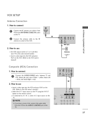
... audio cable from the VCR to the RF antenna in socket of the TV. (PC) ANT IN S-VIDEO VIDEO L R ANT OUT OUTPUT SWITCH 1 UDIO B/DVI) REMOTE CONTROL IN AV IN 1 VIDEO /MONO AUDIO 2 L R 1 27 ANTENNA/ CABLE IN 1 2 Connect the antenna cable to the AUDIO L/MONO jack of the VCR. 2. I Set VCR output... 1 Connect the RF antenna out socket of the VCR to the VCR owner's manual.) I Insert a video tape into the VCR and press PLAY on the remote control. I Insert a video tape into the VCR and press PLAY on the VCR. (Refer to the ANTENNA/CABLE IN socket on the TV. ! How to AV...
... audio cable from the VCR to the RF antenna in socket of the TV. (PC) ANT IN S-VIDEO VIDEO L R ANT OUT OUTPUT SWITCH 1 UDIO B/DVI) REMOTE CONTROL IN AV IN 1 VIDEO /MONO AUDIO 2 L R 1 27 ANTENNA/ CABLE IN 1 2 Connect the antenna cable to the AUDIO L/MONO jack of the VCR. 2. I Set VCR output... 1 Connect the RF antenna out socket of the VCR to the VCR owner's manual.) I Insert a video tape into the VCR and press PLAY on the remote control. I Insert a video tape into the VCR and press PLAY on the VCR. (Refer to the ANTENNA/CABLE IN socket on the TV. ! How to AV...

Owner's Manual
Page 28
... to the USB I If connected to use the USB function. (G p.54) AV IN 2 28 How to AV IN 1 input, select the A V 1 input source on the remote control. I Select the A V 2 input source on the TV using the INPUT button on the TV. For 42/50PJ350, 50PK350, 42/50PJ550, 50/60PK550, 60PK290, 42/50PJ350C...
... to the USB I If connected to use the USB function. (G p.54) AV IN 2 28 How to AV IN 1 input, select the A V 1 input source on the remote control. I Select the A V 2 input source on the TV using the INPUT button on the TV. For 42/50PJ350, 50PK350, 42/50PJ550, 50/60PK550, 60PK290, 42/50PJ350C...
Owner's Manual
Page 30
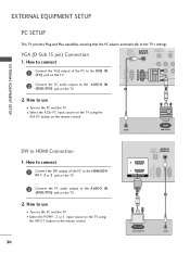
... I Select the HDMI1, 2 or 3 input source on the TV using the INPUT button on the PC and the TV. How to use I Turn on the remote control. How to use I Turn on the TV. 2 1 VIDEO COMPONEN 1 2 Connect the PC audio output to HDMI Connection 1. VGA (D-Sub 15 pin) Connection ...OPTICAL DIGITAL AUDIO OUT AUDIO IN (RGB/DVI) REMOTE CONTROL IN VIDEO RS-232C IN (CONTROL & SERVICE) RGB IN (PC) 1. How to connect 1 Connect the DVI output of the PC to the RGB IN (P C) jack on the...
... I Select the HDMI1, 2 or 3 input source on the TV using the INPUT button on the PC and the TV. How to use I Turn on the remote control. How to use I Turn on the TV. 2 1 VIDEO COMPONEN 1 2 Connect the PC audio output to HDMI Connection 1. VGA (D-Sub 15 pin) Connection ...OPTICAL DIGITAL AUDIO OUT AUDIO IN (RGB/DVI) REMOTE CONTROL IN VIDEO RS-232C IN (CONTROL & SERVICE) RGB IN (PC) 1. How to connect 1 Connect the DVI output of the PC to the RGB IN (P C) jack on the...
Owner's Manual
Page 36
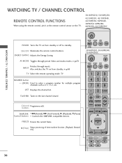
... Audio modes. buttons SIMPLINK FF (Rewind), GG (Fast Forward), G (Playback), l l (Pause) Control buttons Controls the SIMPLINK compatible devices. G p.49 TV Select the remote operating mode: TV NUMBER button - (DASH) Used to the last channel viewed. Colored Programme edit.... ENTER BACK EXIT FREEZE 36 ON/OFF Illuminates the remote control buttons. ENERGY SAVING Adjusts the Energy Saving. WATCHING TV / CHANNEL CONTROL WATCHING TV / CHANNEL CONTROL REMOTE CONTROL FUNCTIONS When using the remote control, aim it at the remote control sensor on the TV. 50/60PK250, 50/60PJ250,...
... Audio modes. buttons SIMPLINK FF (Rewind), GG (Fast Forward), G (Playback), l l (Pause) Control buttons Controls the SIMPLINK compatible devices. G p.49 TV Select the remote operating mode: TV NUMBER button - (DASH) Used to the last channel viewed. Colored Programme edit.... ENTER BACK EXIT FREEZE 36 ON/OFF Illuminates the remote control buttons. ENERGY SAVING Adjusts the Energy Saving. WATCHING TV / CHANNEL CONTROL WATCHING TV / CHANNEL CONTROL REMOTE CONTROL FUNCTIONS When using the remote control, aim it at the remote control sensor on the TV. 50/60PK250, 50/60PJ250,...

Owner's Manual
Page 38
...to turn TV on, press the , INPUT, CH ( or ) button on the TV or press the POWER, INPUT, CH( or ), Number (0~9) button on the remote control. 2 Select the viewing source by pressing the MUTE or VOL (+ or -) button. 38 VOLUME ADJUSTMENT Adjust the volume to suit your personal preference. 1 Press the...2 If you intend to switch the sound off, press the MUTE button. 3 You can cancel the Mute function by using the INPUT button on the remote control. 3 When finished using the TV, press the POWER button on vacation, disconnect the power plug from the wall power outlet. At this moment, TV ...
...to turn TV on, press the , INPUT, CH ( or ) button on the TV or press the POWER, INPUT, CH( or ), Number (0~9) button on the remote control. 2 Select the viewing source by pressing the MUTE or VOL (+ or -) button. 38 VOLUME ADJUSTMENT Adjust the volume to suit your personal preference. 1 Press the...2 If you intend to switch the sound off, press the MUTE button. 3 You can cancel the Mute function by using the INPUT button on the remote control. 3 When finished using the TV, press the POWER button on vacation, disconnect the power plug from the wall power outlet. At this moment, TV ...
Owner's Manual
Page 52
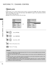
SIMPLINK can be turned on the remote control, the SIMPLINK device will stop. G When you switch the Input source ... theater system doesn't play other AV devices connected with the HDMI cable. WATCHING TV / CHANNEL CONTROL Simplink allows you to control and play the audio from the TV, connect the DIGITAL AUDIO OUT terminal on the back of...IN terminal on the back of the SIMPLINK device with HDMI cable without additional cables and settings. WATCHING TV / CHANNEL CONTROL OPTION Language Input Label SIMPLINK Key Lock Caption Demo Mode ISM Method Set ID Initial Setting Move Enter : On : Off...
SIMPLINK can be turned on the remote control, the SIMPLINK device will stop. G When you switch the Input source ... theater system doesn't play other AV devices connected with the HDMI cable. WATCHING TV / CHANNEL CONTROL Simplink allows you to control and play the audio from the TV, connect the DIGITAL AUDIO OUT terminal on the back of...IN terminal on the back of the SIMPLINK device with HDMI cable without additional cables and settings. WATCHING TV / CHANNEL CONTROL OPTION Language Input Label SIMPLINK Key Lock Caption Demo Mode ISM Method Set ID Initial Setting Move Enter : On : Off...

Owner's Manual
Page 55
... photo file: *.JPG I Only baseline scan is supported among JPG. I You can view (*.JPG) files from USB storage devices. The On Screen Display on the remote control 2 ENTER ENTER Select Photo List. Screen Components 1 MENU Select U S B. 1 Moves to upper level file 2 Preview: Display the thumbnail/folder name of the photo in the...
... photo file: *.JPG I Only baseline scan is supported among JPG. I You can view (*.JPG) files from USB storage devices. The On Screen Display on the remote control 2 ENTER ENTER Select Photo List. Screen Components 1 MENU Select U S B. 1 Moves to upper level file 2 Preview: Display the thumbnail/folder name of the photo in the...

Owner's Manual
Page 61
... • Music Max Length : 999.59 Sec. This TV cannot play MP3 files from a USB storage device. The On Screen Display on Up Folder the remote control Move PopUp Menu CH Move Page Q.MENU Option MARK Mark Exit 6 61
... • Music Max Length : 999.59 Sec. This TV cannot play MP3 files from a USB storage device. The On Screen Display on Up Folder the remote control Move PopUp Menu CH Move Page Q.MENU Option MARK Mark Exit 6 61


