Owner's Manual
Page 6
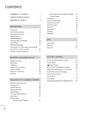
... 22 DVD Setup 25 VCR Setup 27 Other A/V Source Setup 28 USB Connection 28 Audio Out Connection 29 PC Setup 30 WATCHING TV / CHANNEL CONTROL Remote Control Functions 36 Turning On TV 38 Channel Selection 38 Volume Adjustment 38 Initial Setting 39 On-Screen Menus Selection 40 Quick Menu 42 Channel...
... 22 DVD Setup 25 VCR Setup 27 Other A/V Source Setup 28 USB Connection 28 Audio Out Connection 29 PC Setup 30 WATCHING TV / CHANNEL CONTROL Remote Control Functions 36 Turning On TV 38 Channel Selection 38 Volume Adjustment 38 Initial Setting 39 On-Screen Menus Selection 40 Quick Menu 42 Channel...
Owner's Manual
Page 9
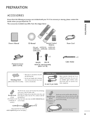
... EXIT FREEZE Q.MENU or 753 86 LIST 0 9 MENU VOL FAVMARK MUTERATIO CH FLASHBK INFO P A G E ENTER Q.MENU BACK 1.5V 1.5V EXIT FREEZE Owner's Manual CD Manual Remote Control, Batteries (Except 60PK250, 60PK540, 60PK550, 60PK280, 60PK290, 60PK550C) Power Cord Protection Cover (Refer to P.16) x 4 x 3 M4x28 M5x14 Bolts for all models) scratch or discoloration...
... EXIT FREEZE Q.MENU or 753 86 LIST 0 9 MENU VOL FAVMARK MUTERATIO CH FLASHBK INFO P A G E ENTER Q.MENU BACK 1.5V 1.5V EXIT FREEZE Owner's Manual CD Manual Remote Control, Batteries (Except 60PK250, 60PK540, 60PK550, 60PK280, 60PK290, 60PK550C) Power Cord Protection Cover (Refer to P.16) x 4 x 3 M4x28 M5x14 Bolts for all models) scratch or discoloration...
Owner's Manual
Page 10
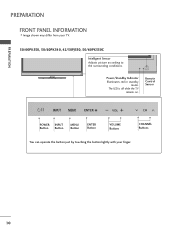
PREPARATION PREPARATION FRONT PANEL INFORMATION I Image shown may differ from your finger. 10 The LED is off while the TV remains on. ENTER VOL CH Power/Standby Indicator Illuminates red in standby mode. Remote Control Sensor ENTER VOL CH POWER INPUT Button Button MENU Button ENTER Button VOLUME Buttons CHANNEL Buttons ENTER You can operate the button just by touching the button lightly with your TV. 50/60PK550, 50/60PK540, 42/50PJ550, 50/60PK550C Intelligent Sensor Adjusts picture according to the surrounding conditions.
PREPARATION PREPARATION FRONT PANEL INFORMATION I Image shown may differ from your finger. 10 The LED is off while the TV remains on. ENTER VOL CH Power/Standby Indicator Illuminates red in standby mode. Remote Control Sensor ENTER VOL CH POWER INPUT Button Button MENU Button ENTER Button VOLUME Buttons CHANNEL Buttons ENTER You can operate the button just by touching the button lightly with your TV. 50/60PK550, 50/60PK540, 42/50PJ550, 50/60PK550C Intelligent Sensor Adjusts picture according to the surrounding conditions.

Owner's Manual
Page 11
PREPARATION 50/60PK250, 42/50PJ250, 60PK280, 60PK290 Intelligent Sensor Adjusts picture according to the surrounding conditions. Remote Control Sensor ENTER VOL CH POWER INPUT Button Button MENU Button ENTER Button VOLUME Buttons CHANNEL Buttons ENTER You can operate the button just by touching the button lightly with your finger. 11 The LED is off while the TV remains on. ENTER VOL CH Power/Standby Indicator Illuminates red in standby mode.
PREPARATION 50/60PK250, 42/50PJ250, 60PK280, 60PK290 Intelligent Sensor Adjusts picture according to the surrounding conditions. Remote Control Sensor ENTER VOL CH POWER INPUT Button Button MENU Button ENTER Button VOLUME Buttons CHANNEL Buttons ENTER You can operate the button just by touching the button lightly with your finger. 11 The LED is off while the TV remains on. ENTER VOL CH Power/Standby Indicator Illuminates red in standby mode.

Owner's Manual
Page 12
... LED is off while the TV remains on the glass stand or subject it to the surrounding conditions. The floor or the product may fall. Remote Control Sensor ENTER VOL CH VOL POWER Button INPUT Button CH MENU Button ENTER Button VOLUME Buttons CHANNEL Buttons You can operate the button just...
... LED is off while the TV remains on the glass stand or subject it to the surrounding conditions. The floor or the product may fall. Remote Control Sensor ENTER VOL CH VOL POWER Button INPUT Button CH MENU Button ENTER Button VOLUME Buttons CHANNEL Buttons You can operate the button just...
Owner's Manual
Page 13
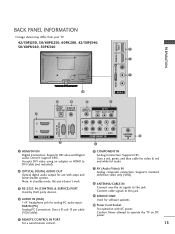
...your TV. 42/50PJ250, 50/60PK250, 60PK280, 42/50PJ340, 50/60PK540, 50PK340 9 1 7 10 AV IN 2 2 4 5 7 OPTICAL DIGITAL AUDIO OUT AUDIO IN (RGB/DVI) REMOTE CONTROL IN AV IN 1 VIDEO /MONO AUDIO 1 () VARIABLE AUDIO OUT 2 1 HDMI/DVI IN 3 RS-232C IN (CONTROL & SERVICE) RGB IN (PC) 2 L R 1 ...CABLE IN Connect over-the air signals to operate the TV on DC power. 13 Uses a D-sub 15 pin cable (VGA cable). 5 REMOTE CONTROL IN PORT For a wired remote control. 6 COMPONENT IN Analog Connection. Supports HD. Caution: Never attempt to this port doesn't work. 3 RS-232C IN (CONTROL & ...
...your TV. 42/50PJ250, 50/60PK250, 60PK280, 42/50PJ340, 50/60PK540, 50PK340 9 1 7 10 AV IN 2 2 4 5 7 OPTICAL DIGITAL AUDIO OUT AUDIO IN (RGB/DVI) REMOTE CONTROL IN AV IN 1 VIDEO /MONO AUDIO 1 () VARIABLE AUDIO OUT 2 1 HDMI/DVI IN 3 RS-232C IN (CONTROL & SERVICE) RGB IN (PC) 2 L R 1 ...CABLE IN Connect over-the air signals to operate the TV on DC power. 13 Uses a D-sub 15 pin cable (VGA cable). 5 REMOTE CONTROL IN PORT For a wired remote control. 6 COMPONENT IN Analog Connection. Supports HD. Caution: Never attempt to this port doesn't work. 3 RS-232C IN (CONTROL & ...

Owner's Manual
Page 14
... PORT 5 For a wired remote control. 6 COMPONENT IN Analog Connection. Supports standard definition video only (480i). 8 ANTENNA/CABLE IN Connect over-the air signals to DVI cable (not included) 2 OPTICAL ... R R PREPARATION 42/50PJ350, 50PK350, 50/60PK550, 42/50PJ550, 60PK290, 42/50PJ350C, 50/60PK550C 9 1 PREPARATION 7 10 AV IN 2 2 4 5 7 OPTICAL DIGITAL AUDIO OUT AUDIO IN (RGB/DVI) REMOTE CONTROL IN AV IN 1 VIDEO /MONO AUDIO 1 () VARIABLE AUDIO OUT 2 1 HDMI/DVI IN 3 RS-232C IN (CONTROL & SERVICE) RGB IN (PC) 2 L R 1 VIDEO AUDIO COMPONENT IN...
... PORT 5 For a wired remote control. 6 COMPONENT IN Analog Connection. Supports standard definition video only (480i). 8 ANTENNA/CABLE IN Connect over-the air signals to DVI cable (not included) 2 OPTICAL ... R R PREPARATION 42/50PJ350, 50PK350, 50/60PK550, 42/50PJ550, 60PK290, 42/50PJ350C, 50/60PK550C 9 1 PREPARATION 7 10 AV IN 2 2 4 5 7 OPTICAL DIGITAL AUDIO OUT AUDIO IN (RGB/DVI) REMOTE CONTROL IN AV IN 1 VIDEO /MONO AUDIO 1 () VARIABLE AUDIO OUT 2 1 HDMI/DVI IN 3 RS-232C IN (CONTROL & SERVICE) RGB IN (PC) 2 L R 1 VIDEO AUDIO COMPONENT IN...
Owner's Manual
Page 22
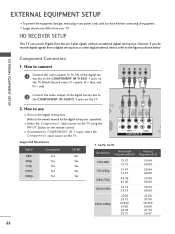
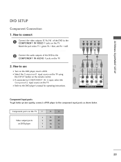
... the video outputs (Y, PB, PR) of the digital set -top box. How to COMPONENT IN 2 input, select the Component2 input source on the remote control. EXTERNAL EQUIPMENT SETUP Component Connection 1. Y PB PR L R 2 Connect the audio output of the digital settop box to the COMPONENT IN AUDIO ... from your TV. operation) I Select the Component1 input source on the TV using the INPUT button on the TV. 1 2 O IN /DVI) REMOTE CONTROL IN AV IN 1 VIDEO /MONO AUDIO 2 L R 1 VIDEO AUDIO COMPONENT IN ANT CA Supported Resolutions Signal 480i 480p 720p 1080i 1080p Component ...
... the video outputs (Y, PB, PR) of the digital set -top box. How to COMPONENT IN 2 input, select the Component2 input source on the remote control. EXTERNAL EQUIPMENT SETUP Component Connection 1. Y PB PR L R 2 Connect the audio output of the digital settop box to the COMPONENT IN AUDIO ... from your TV. operation) I Select the Component1 input source on the TV using the INPUT button on the TV. 1 2 O IN /DVI) REMOTE CONTROL IN AV IN 1 VIDEO /MONO AUDIO 2 L R 1 VIDEO AUDIO COMPONENT IN ANT CA Supported Resolutions Signal 480i 480p 720p 1080i 1080p Component ...
Owner's Manual
Page 23
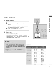
... over version 1.3. If the HDMI cables don't support HDMI version 1.3, it can cause flickers or no screen display. In this case use I Turn on the remote control. HDMI-DTV Resolution Horizontal Vertical Frequency(KHz) Frequency(Hz) 720x480p 1280x720p 1920x1080i 1920x1080p 31.47 31.47 44.96 45.00 33.72 33...
... over version 1.3. If the HDMI cables don't support HDMI version 1.3, it can cause flickers or no screen display. In this case use I Turn on the remote control. HDMI-DTV Resolution Horizontal Vertical Frequency(KHz) Frequency(Hz) 720x480p 1280x720p 1920x1080i 1920x1080p 31.47 31.47 44.96 45.00 33.72 33...
Owner's Manual
Page 24
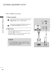
...) RGB IN (PC) 2 2 1 1 HDMI/DVI IN 1 2 DVI-DTV OUTPUT R L 24 NOTE G A DVI to the owner's manual for the digital set-top box.) I Turn on the remote control. ! Connect the audio output of the digital set -top box to the HDMI/DVI IN 1, 2 or 3 jack on the TV. 2. How to connect 1 Connect...
...) RGB IN (PC) 2 2 1 1 HDMI/DVI IN 1 2 DVI-DTV OUTPUT R L 24 NOTE G A DVI to the owner's manual for the digital set-top box.) I Turn on the remote control. ! Connect the audio output of the digital set -top box to the HDMI/DVI IN 1, 2 or 3 jack on the TV. 2. How to connect 1 Connect...
Owner's Manual
Page 25
I Refer to the DVD player's manual for operating instructions. 1 2 DIO IN B/DVI) REMOTE CONTROL IN AV IN 1 VIDEO /MONO AUDIO 2 L R 1 VIDEO AUDIO A COMPONENT IN Component Input ports To get better picture quality, connect a DVD player to the COMPONENT ..., PB = blue, and PR = red). Y PB PR L R 2 Connect the audio outputs of the DVD to COMPONENT IN 2 input, select the Component2 input source on the remote control. I Turn on the TV. 2. EXTERNAL EQUIPMENT SETUP DVD SETUP Component Connection 1.
I Refer to the DVD player's manual for operating instructions. 1 2 DIO IN B/DVI) REMOTE CONTROL IN AV IN 1 VIDEO /MONO AUDIO 2 L R 1 VIDEO AUDIO A COMPONENT IN Component Input ports To get better picture quality, connect a DVD player to the COMPONENT ..., PB = blue, and PR = red). Y PB PR L R 2 Connect the audio outputs of the DVD to COMPONENT IN 2 input, select the Component2 input source on the remote control. I Turn on the TV. 2. EXTERNAL EQUIPMENT SETUP DVD SETUP Component Connection 1.

Owner's Manual
Page 26
HDMI supports both audio and video. 2. How to use I Refer to the HDMI/DVI IN 1, 2 or 3 jack on the remote control. How to connect 1 Connect the HDMI output of the DVD to the DVD player's manual for operating instructions. I Select the HDMI1, 2 or 3 input source on the TV using the INPUT button on the TV. 2 No separate audio connection is necessary. HDMI-DVD OUTPUT 1 OPTICAL DIGITAL AUDIO OUT AUD (RGB/D 2 1 HDMI/DVI IN RS-232C IN (CONTROL & SERVICE) RGB IN (PC) 26 EXTERNAL EQUIPMENT SETUP EXTERNAL EQUIPMENT SETUP HDMI Connection 1.
HDMI supports both audio and video. 2. How to use I Refer to the HDMI/DVI IN 1, 2 or 3 jack on the remote control. How to connect 1 Connect the HDMI output of the DVD to the DVD player's manual for operating instructions. I Select the HDMI1, 2 or 3 input source on the TV using the INPUT button on the TV. 2 No separate audio connection is necessary. HDMI-DVD OUTPUT 1 OPTICAL DIGITAL AUDIO OUT AUD (RGB/D 2 1 HDMI/DVI IN RS-232C IN (CONTROL & SERVICE) RGB IN (PC) 26 EXTERNAL EQUIPMENT SETUP EXTERNAL EQUIPMENT SETUP HDMI Connection 1.
Owner's Manual
Page 27
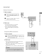
I Insert a video tape into the VCR and press PLAY on the remote control. How to connect 1 Connect the RF antenna out socket of the VCR to the ANTENNA/CABLE IN socket on the TV. ! How to the .... How to use I If connected to the RF antenna in socket of the TV. (PC) ANT IN S-VIDEO VIDEO L R ANT OUT OUTPUT SWITCH 1 UDIO B/DVI) REMOTE CONTROL IN AV IN 1 VIDEO /MONO AUDIO 2 L R 1 27
I Insert a video tape into the VCR and press PLAY on the remote control. How to connect 1 Connect the RF antenna out socket of the VCR to the ANTENNA/CABLE IN socket on the TV. ! How to the .... How to use I If connected to the RF antenna in socket of the TV. (PC) ANT IN S-VIDEO VIDEO L R ANT OUT OUTPUT SWITCH 1 UDIO B/DVI) REMOTE CONTROL IN AV IN 1 VIDEO /MONO AUDIO 2 L R 1 27

Owner's Manual
Page 28
... USB CONNECTION - EXTERNAL EQUIPMENT SETUP OTHER A/V SOURCE SETUP 1. How to connect i.e) 1 1 Connect the USB device to AV IN 1 input, select the A V 1 input source on the remote control. How to connect 1 Connect the AUDIO/VIDEO jacks between TV and external equipment. Match the jack colors. (Video = yellow, Audio Left = white, and Audio...
... USB CONNECTION - EXTERNAL EQUIPMENT SETUP OTHER A/V SOURCE SETUP 1. How to connect i.e) 1 1 Connect the USB device to AV IN 1 input, select the A V 1 input source on the remote control. How to connect 1 Connect the AUDIO/VIDEO jacks between TV and external equipment. Match the jack colors. (Video = yellow, Audio Left = white, and Audio...
Owner's Manual
Page 30
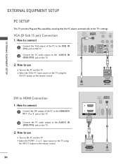
I Select the HDMI1, 2 or 3 input source on the TV using the INPUT button on the remote control. 30 OPTICAL AUDIO IN DIGITAL AUDIO OUT (RGB/DVI) 2 1 HDMI/DVI IN RS-232C IN (CONTROL & SERVICE) RGB IN (PC) 1 2 DVI-PC OUTPUT AUDIO ... on the TV. 2 Connect the PC audio output to use I Select the RGB-PC input source on the TV using the INPUT button on the remote control. I Turn on the PC and the TV. VGA (D-Sub 15 pin) Connection OPTICAL DIGITAL AUDIO OUT AUDIO IN (RGB/DVI...
I Select the HDMI1, 2 or 3 input source on the TV using the INPUT button on the remote control. 30 OPTICAL AUDIO IN DIGITAL AUDIO OUT (RGB/DVI) 2 1 HDMI/DVI IN RS-232C IN (CONTROL & SERVICE) RGB IN (PC) 1 2 DVI-PC OUTPUT AUDIO ... on the TV. 2 Connect the PC audio output to use I Select the RGB-PC input source on the TV using the INPUT button on the remote control. I Turn on the PC and the TV. VGA (D-Sub 15 pin) Connection OPTICAL DIGITAL AUDIO OUT AUDIO IN (RGB/DVI...
Owner's Manual
Page 36
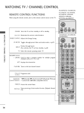
...), l l (Pause) Control buttons Controls the SIMPLINK compatible devices. G p.51 Rotates through preset Video and Audio modes. G p.49 TV Select the remote operating mode: TV NUMBER button - (DASH) Used to the last channel viewed. WATCHING TV / CHANNEL CONTROL WATCHING TV / CHANNEL CONTROL... REMOTE CONTROL FUNCTIONS When using the remote control, aim it at the remote control sensor on the TV. 50/60PK250, 50/60PJ250, 42/50PJ350, 42/50PJ340, 42/50PJ550, 50PK340, 50PK350,...
...), l l (Pause) Control buttons Controls the SIMPLINK compatible devices. G p.51 Rotates through preset Video and Audio modes. G p.49 TV Select the remote operating mode: TV NUMBER button - (DASH) Used to the last channel viewed. WATCHING TV / CHANNEL CONTROL WATCHING TV / CHANNEL CONTROL... REMOTE CONTROL FUNCTIONS When using the remote control, aim it at the remote control sensor on the TV. 50/60PK250, 50/60PJ250, 42/50PJ350, 42/50PJ340, 42/50PJ550, 50PK340, 50PK350,...

Owner's Manual
Page 38
.... ! The TV reverts to switch the sound off, press the MUTE button. 3 You can cancel the Mute function by using the INPUT button on the remote control. 3 When finished using the TV, press the POWER button on vacation, disconnect the power plug from the wall power outlet. VOLUME ADJUSTMENT Adjust the...intend to turn TV on, press the , INPUT, CH ( or ) button on the TV or press the POWER, INPUT, CH( or ), Number (0~9) button on the remote control. 2 Select the viewing source by pressing the MUTE or VOL (+ or -) button. 38 CHANNEL SELECTION 1 Press the CH ( or ) or NUMBER buttons to select...
.... ! The TV reverts to switch the sound off, press the MUTE button. 3 You can cancel the Mute function by using the INPUT button on the remote control. 3 When finished using the TV, press the POWER button on vacation, disconnect the power plug from the wall power outlet. VOLUME ADJUSTMENT Adjust the...intend to turn TV on, press the , INPUT, CH ( or ) button on the TV or press the POWER, INPUT, CH( or ), Number (0~9) button on the remote control. 2 Select the viewing source by pressing the MUTE or VOL (+ or -) button. 38 CHANNEL SELECTION 1 Press the CH ( or ) or NUMBER buttons to select...
Owner's Manual
Page 52
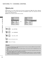
... the SIMPLINK device with an OPTICAL cable. 52 WATCHING TV / CHANNEL CONTROL Simplink allows you switch the Input source with the INPUT button on the remote control, the SIMPLINK device will stop.
... the SIMPLINK device with an OPTICAL cable. 52 WATCHING TV / CHANNEL CONTROL Simplink allows you switch the Input source with the INPUT button on the remote control, the SIMPLINK device will stop.

Owner's Manual
Page 55
... 1 0 folder, 4 file(s) Up Folder Move PopUp Menu CH Move Page 6 MARK Mark 5 USB Device Free Space 150MB Exit 55 The On Screen Display on the remote control 2 ENTER ENTER Select Photo List. Screen Components 1 MENU Select U S B. 1 Moves to upper level file 2 Preview: Display the thumbnail/folder name of the photo in...
... 1 0 folder, 4 file(s) Up Folder Move PopUp Menu CH Move Page 6 MARK Mark 5 USB Device Free Space 150MB Exit 55 The On Screen Display on the remote control 2 ENTER ENTER Select Photo List. Screen Components 1 MENU Select U S B. 1 Moves to upper level file 2 Preview: Display the thumbnail/folder name of the photo in...

Owner's Manual
Page 61
... different. Screen Components 1 MENU Select U S B. 2 ENTER ENTER Select Music List. 1 Moves to play back copy-protected files. The On Screen Display on Up Folder the remote control Move PopUp Menu CH Move Page Q.MENU Option MARK Mark Exit 6 61
... different. Screen Components 1 MENU Select U S B. 2 ENTER ENTER Select Music List. 1 Moves to play back copy-protected files. The On Screen Display on Up Folder the remote control Move PopUp Menu CH Move Page Q.MENU Option MARK Mark Exit 6 61


