Owners Manual
Page 2
... this product to operate this product in a particular installation. NO USER SERVICEABLE PARTS INSIDE. Connect the equipment to constitute a risk of the following measures: - FCC NOTICE Class B digital device This equipment has been tested and found to comply with the instructions, may be determined by turning the equipment off and on a circuit different from LG Electronics. Reorient or relocate the receiving antenna. -
... this product to operate this product in a particular installation. NO USER SERVICEABLE PARTS INSIDE. Connect the equipment to constitute a risk of the following measures: - FCC NOTICE Class B digital device This equipment has been tested and found to comply with the instructions, may be determined by turning the equipment off and on a circuit different from LG Electronics. Reorient or relocate the receiving antenna. -
Owners Manual
Page 4
..., pinched, closed in a door, or walked upon a dedicated circuit; Do not install this product to install the TV by connecting it , discontinue use a damaged or loose power cord. Check the specification page of fire or electrical shock, do grasp the plug when unplugging the power cord. Protect the power cord from direct sunlight. 2 Do not use of the appliance, and have the cord replaced with something...
..., pinched, closed in a door, or walked upon a dedicated circuit; Do not install this product to install the TV by connecting it , discontinue use a damaged or loose power cord. Check the specification page of fire or electrical shock, do grasp the plug when unplugging the power cord. Protect the power cord from direct sunlight. 2 Do not use of the appliance, and have the cord replaced with something...
Owners Manual
Page 5
... TV or hear strange sounds, unplug the power cord contact an authorized service center. 25 Do not press strongly upon the panel with chemicals such as to grounding electrodes and requirements for the grounding electrode. Do not install in wire to an antenna discharge unit, size of grounding conductors, location of the TV. 23 Ventilation Install your TV where there...
... TV or hear strange sounds, unplug the power cord contact an authorized service center. 25 Do not press strongly upon the panel with chemicals such as to grounding electrodes and requirements for the grounding electrode. Do not install in wire to an antenna discharge unit, size of grounding conductors, location of the TV. 23 Ventilation Install your TV where there...
Owners Manual
Page 6
...Mode 72 Initializing (Reset to a Desk 18 VESA Wall Mounting 19 Desktop Pedestal Installation 19 Antenna or Cable Connection 20 EXTERNAL EQUIPMENT SETUP HD Receiver Setup 21 DVD Setup 24 VCR Setup 26 Other A/V Source Setup 28 Digital Audio Output 28 PC Setup 29 WATCHING TV / CHANNEL CONTROL Remote Control Functions 32 Turning On TV 34 Channel Selection 34 Volume Adjustment 34 On-Screen Menus Selection 35 Channel Setup 36 - Black (Darkness) Level 51 4 Picture Reset 52 Low-Power Picture Mode 52 Image Sticking Minimization( ISM) Method 53 SOUND & LANGUAGE CONTROL Auto...
...Mode 72 Initializing (Reset to a Desk 18 VESA Wall Mounting 19 Desktop Pedestal Installation 19 Antenna or Cable Connection 20 EXTERNAL EQUIPMENT SETUP HD Receiver Setup 21 DVD Setup 24 VCR Setup 26 Other A/V Source Setup 28 Digital Audio Output 28 PC Setup 29 WATCHING TV / CHANNEL CONTROL Remote Control Functions 32 Turning On TV 34 Channel Selection 34 Volume Adjustment 34 On-Screen Menus Selection 35 Channel Setup 36 - Black (Darkness) Level 51 4 Picture Reset 52 Low-Power Picture Mode 52 Image Sticking Minimization( ISM) Method 53 SOUND & LANGUAGE CONTROL Auto...
Owners Manual
Page 11
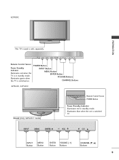
INPUT MENU ENTER VOL CH Remote Control Sensor Power/Standby Indicator Illuminates red when the TV is switched on . Illuminates green when the TV is in standby mode. INPUT MENU ENTER VOL CH INPUT MENU ENTER VOL CH INPUT MENU ENTER VOL CH INPUT Button MENU Button ENTER Button VOLUME (-,+) Buttons CHANNEL (E, D) Buttons 9 POWER Button INPUT Button MENU Button ENTER Button VOLUME Buttons CHANNEL Buttons 42PG60C, 42PG65C Stand (Only 42PG65C model) Remote Control Sensor POWER Button Power/Standby Indicator Illuminates red in standby mode. INPUT ENTER ...
INPUT MENU ENTER VOL CH Remote Control Sensor Power/Standby Indicator Illuminates red when the TV is switched on . Illuminates green when the TV is in standby mode. INPUT MENU ENTER VOL CH INPUT MENU ENTER VOL CH INPUT MENU ENTER VOL CH INPUT Button MENU Button ENTER Button VOLUME (-,+) Buttons CHANNEL (E, D) Buttons 9 POWER Button INPUT Button MENU Button ENTER Button VOLUME Buttons CHANNEL Buttons 42PG60C, 42PG65C Stand (Only 42PG65C model) Remote Control Sensor POWER Button Power/Standby Indicator Illuminates red in standby mode. INPUT ENTER ...
Owners Manual
Page 13
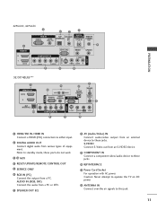
... IN COMPONENT IN L R VIDEO 9 AUDIO 5 AUDIO VIDEO L(MONO) R 8 32/37/42LG5*** 1 HDMI/DVI IN 1(DVI) 2 RJP INTERFACE 10 4 2 6 RESET UPDATE OPTICAL DIGITAL AUDIO OUT RGB(PC) AUDIO (RGB/DVI) RS-232C IN (SERVICE ONLY) 7 SPEAKER OUT 8 REMOTE CONTROL OUT 4 RGB IN AV IN 1 VIDEO AUDIO COMPONENT IN 9 S-VIDEO 5 AUDIO L/MONO VIDEO 8 1 HDMI/DVI IN, HDMI IN Connect a HDMI (DVI) connection to either input. 2 DIGITAL AUDIO OUT Connect digital audio from an external device to these jacks. 10 RJP INTERFACE 11 Power Cord Socket For operation with AC power...
... IN COMPONENT IN L R VIDEO 9 AUDIO 5 AUDIO VIDEO L(MONO) R 8 32/37/42LG5*** 1 HDMI/DVI IN 1(DVI) 2 RJP INTERFACE 10 4 2 6 RESET UPDATE OPTICAL DIGITAL AUDIO OUT RGB(PC) AUDIO (RGB/DVI) RS-232C IN (SERVICE ONLY) 7 SPEAKER OUT 8 REMOTE CONTROL OUT 4 RGB IN AV IN 1 VIDEO AUDIO COMPONENT IN 9 S-VIDEO 5 AUDIO L/MONO VIDEO 8 1 HDMI/DVI IN, HDMI IN Connect a HDMI (DVI) connection to either input. 2 DIGITAL AUDIO OUT Connect digital audio from an external device to these jacks. 10 RJP INTERFACE 11 Power Cord Socket For operation with AC power...
Owners Manual
Page 23
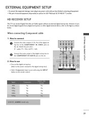
... the set. 2. Match the jack colors (Y = green, PB = blue, and PR = red). HDMI/DVI IN 1(DVI) 1 2 DIGITAL AUDIO OUT (OPTICAL) 2 M.P.I. How to connect 1 Connect the video outputs (Y, PB, PR) of the digital set top box to 2 the COMPONENT IN AUDIO jacks on the set. EXTERNAL EQUIPMENT SETUP EXTERNAL EQUIPMENT SETUP ■ To prevent the equipment damage, never plug in any power cords until you do receive digital signals from a digital set-top box or other digital external device, refer to the owner's manual for LCD TV...
... the set. 2. Match the jack colors (Y = green, PB = blue, and PR = red). HDMI/DVI IN 1(DVI) 1 2 DIGITAL AUDIO OUT (OPTICAL) 2 M.P.I. How to connect 1 Connect the video outputs (Y, PB, PR) of the digital set top box to 2 the COMPONENT IN AUDIO jacks on the set. EXTERNAL EQUIPMENT SETUP EXTERNAL EQUIPMENT SETUP ■ To prevent the equipment damage, never plug in any power cords until you do receive digital signals from a digital set-top box or other digital external device, refer to the owner's manual for LCD TV...
Owners Manual
Page 24
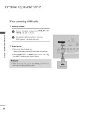
...input source with using the INPUT button on the set. 2 No separated audio connection is necessary. HDMI/DVI IN 1(DVI) DIGITAL AUDIO OUT (OPTICAL) 2 M.P.I RJP INTERFACE 1 VIDEO AUDIO COMPONENT IN HDMI-DTV OUTPUT ( ) 22 HDMI supports both audio and video. 2. How to use ■ Turn on the digital set-top box. ( ) (Refer to HDMI/DVI IN 1(DVI) or 2 jack on the remote control. How to connect 1 Connect the digital set-top box to the owner's manual for the digital set the output resolution appropriately. EXTERNAL EQUIPMENT SETUP EXTERNAL EQUIPMENT SETUP When connecting HDMI cable...
...input source with using the INPUT button on the set. 2 No separated audio connection is necessary. HDMI/DVI IN 1(DVI) DIGITAL AUDIO OUT (OPTICAL) 2 M.P.I RJP INTERFACE 1 VIDEO AUDIO COMPONENT IN HDMI-DTV OUTPUT ( ) 22 HDMI supports both audio and video. 2. How to use ■ Turn on the digital set-top box. ( ) (Refer to HDMI/DVI IN 1(DVI) or 2 jack on the remote control. How to connect 1 Connect the digital set-top box to the owner's manual for the digital set the output resolution appropriately. EXTERNAL EQUIPMENT SETUP EXTERNAL EQUIPMENT SETUP When connecting HDMI cable...
Owners Manual
Page 25
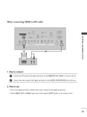
... the owner's manual for the digital set-top box.) ■ Select HDMI1/DVI or HDMI2 input source with using the INPUT button on the set -top box to DVI cable HDMI/DVI IN 1(DVI) DIGITAL AUDIO OUT (OPTICAL) 2 M.P.I. How to connect 1 Connect the DVI output of the digital set-top box to the HDMI/DVI IN 1(DVI) or 2 jack on the set. 2 Connect the audio output of the digital set . 2. RESET UPDATE REMOTE CONTROL OUT SERVICE ONLY RGB IN RJP INTERFACE 1 VIDEO AUDIO COMPONENT IN S-VIDEO (MONO) AUDIO AV IN 1 VIDEO SPEAKER AUDIO...
... the owner's manual for the digital set-top box.) ■ Select HDMI1/DVI or HDMI2 input source with using the INPUT button on the set -top box to DVI cable HDMI/DVI IN 1(DVI) DIGITAL AUDIO OUT (OPTICAL) 2 M.P.I. How to connect 1 Connect the DVI output of the digital set-top box to the HDMI/DVI IN 1(DVI) or 2 jack on the set. 2 Connect the audio output of the digital set . 2. RESET UPDATE REMOTE CONTROL OUT SERVICE ONLY RGB IN RJP INTERFACE 1 VIDEO AUDIO COMPONENT IN S-VIDEO (MONO) AUDIO AV IN 1 VIDEO SPEAKER AUDIO...
Owners Manual
Page 26
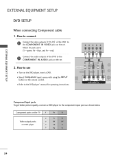
...B-Y R-Y Cb Cr Pb Pr 24 How to the DVD player's manual for operating instructions. Component ports on the TV Y Y Video output ports Y on the DVD player, insert a DVD. Y PB PR L R Connect the audio outputs of the DVD to the component input ports as shown below. Match the jack colors (Y = green, PB = blue, and PR = red). EXTERNAL EQUIPMENT SETUP EXTERNAL EQUIPMENT SETUP DVD SETUP When connecting Component cable 1. HDMI/DVI IN 1(DVI) 1 2 DIGITAL AUDIO OUT (OPTICAL) 2 M.P.I. ■ Select Component input source with using the INPUT button on the set .
...B-Y R-Y Cb Cr Pb Pr 24 How to the DVD player's manual for operating instructions. Component ports on the TV Y Y Video output ports Y on the DVD player, insert a DVD. Y PB PR L R Connect the audio outputs of the DVD to the component input ports as shown below. Match the jack colors (Y = green, PB = blue, and PR = red). EXTERNAL EQUIPMENT SETUP EXTERNAL EQUIPMENT SETUP DVD SETUP When connecting Component cable 1. HDMI/DVI IN 1(DVI) 1 2 DIGITAL AUDIO OUT (OPTICAL) 2 M.P.I. ■ Select Component input source with using the INPUT button on the set .
Owners Manual
Page 27
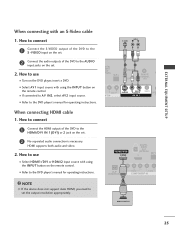
...outputs of the DVD to the S -VIDEO input on the remote control. ( ) ( ■ Refer to the AUDIO input jacks on the set. 2 No separated audio connection is necessary. When connecting with using the INPUT button on the set. RJP INTERFACE VIDEO AUDIO COMPONENT IN 1 NOTE G If the device does not support Auto HDMI, you need to use HDMI/DVI IN 1(DVI) DIGITAL AUDIO OUT (OPTICAL) 2 M.P.I . HDMI supports both audio and video. 2. How to connect 1 Connect the S-VIDEO output of the DVD to the DVD player's manual for operating instructions. How to set the output resolution...
...outputs of the DVD to the S -VIDEO input on the remote control. ( ) ( ■ Refer to the AUDIO input jacks on the set. 2 No separated audio connection is necessary. When connecting with using the INPUT button on the set. RJP INTERFACE VIDEO AUDIO COMPONENT IN 1 NOTE G If the device does not support Auto HDMI, you need to use HDMI/DVI IN 1(DVI) DIGITAL AUDIO OUT (OPTICAL) 2 M.P.I . HDMI supports both audio and video. 2. How to connect 1 Connect the S-VIDEO output of the DVD to the DVD player's manual for operating instructions. How to set the output resolution...
Owners Manual
Page 29
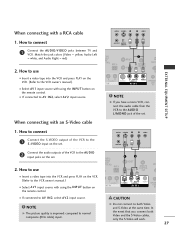
... owner's manual.) ■ Select A V 1 input source with using the INPUT button on the set. How to the AUDIO input jacks on the VCR. (Refer to normal composite (RCA cable) input. ANT IN S-VIDEO L R VIDEO ANT OUT OUTPUT SWITCH 2 Connect the audio outputs of the set . 2. In the event that you have a mono VCR, connect the audio cable from the VCR to both Video and the S-Video cables, only the S-Video will work. 27 Match the jack colors (Video = yellow, Audio Left = white...
... owner's manual.) ■ Select A V 1 input source with using the INPUT button on the set. How to the AUDIO input jacks on the VCR. (Refer to normal composite (RCA cable) input. ANT IN S-VIDEO L R VIDEO ANT OUT OUTPUT SWITCH 2 Connect the audio outputs of the set . 2. In the event that you have a mono VCR, connect the audio cable from the VCR to both Video and the S-Video cables, only the S-Video will work. 27 Match the jack colors (Video = yellow, Audio Left = white...
Owners Manual
Page 30
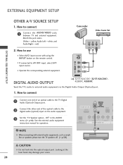
.... Off" in the AUDIO menu. (G p.58). HDMI/DVI IN 1(DVI) DIGITAL AUDIO OUT (OPTICAL) 2 M.P.I. 1 ( RJP VIDEO AUDIO S-V NTERFACE COMPONENT IN 2 NOTE G When connecting with using the INPUT button on the audio equipment. 3 Set the "TV Speaker option - Looking at the laser beam may damage your vision. 28 See the external audio equipment instruction manual for operation. Match the jack colors. (Video = yellow, Audio Left = white, and Audio Right = red) Camcorder Video Game Set VIDEO L R 2. S-VIDEO 1 VIDEO L/MONO AUDIO R AV IN 2 DIGITAL AUDIO OUTPUT i.e) 32/37/42LC5DC...
.... Off" in the AUDIO menu. (G p.58). HDMI/DVI IN 1(DVI) DIGITAL AUDIO OUT (OPTICAL) 2 M.P.I. 1 ( RJP VIDEO AUDIO S-V NTERFACE COMPONENT IN 2 NOTE G When connecting with using the INPUT button on the audio equipment. 3 Set the "TV Speaker option - Looking at the laser beam may damage your vision. 28 See the external audio equipment instruction manual for operation. Match the jack colors. (Video = yellow, Audio Left = white, and Audio Right = red) Camcorder Video Game Set VIDEO L R 2. S-VIDEO 1 VIDEO L/MONO AUDIO R AV IN 2 DIGITAL AUDIO OUTPUT i.e) 32/37/42LC5DC...
Owners Manual
Page 31
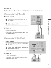
... INTERFACE VIDEO ER AUDIO COMPONENT IN (RGB, DVI) 2. EXTERNAL EQUIPMENT SETUP PC SETUP This TV provides Plug and Play capability, meaning that the PC adjusts automatically to the HDMI/DVI IN 1(DVI) jack on the set . ■ Select RGB-PC input source with using the INPUT button on the remote control. 2 1 When connecting HDMI to use ■ Turn on the PC and the set . When connecting D-sub 15pin cable 1. How to connect 1 Connect the DVI output of the...
... INTERFACE VIDEO ER AUDIO COMPONENT IN (RGB, DVI) 2. EXTERNAL EQUIPMENT SETUP PC SETUP This TV provides Plug and Play capability, meaning that the PC adjusts automatically to the HDMI/DVI IN 1(DVI) jack on the set . ■ Select RGB-PC input source with using the INPUT button on the remote control. 2 1 When connecting HDMI to use ■ Turn on the PC and the set . When connecting D-sub 15pin cable 1. How to connect 1 Connect the DVI output of the...
Owners Manual
Page 32
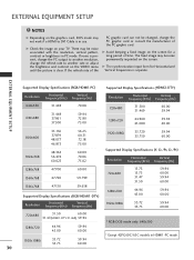
... with the resolution, vertical pattern, contrast or brightness in PC mode. EXTERNAL EQUIPMENT SETUP NOTES G Depending on the graphics card, DOS mode may become permanently imprinted on the screen. The fixed image may not work if a HDMI to DVI Cable is clear. G The synchronization input form for a long period of the PC graphic card. G Check the image on the VIDEO menu until the picture is...
... with the resolution, vertical pattern, contrast or brightness in PC mode. EXTERNAL EQUIPMENT SETUP NOTES G Depending on the graphics card, DOS mode may become permanently imprinted on the screen. The fixed image may not work if a HDMI to DVI Cable is clear. G The synchronization input form for a long period of the PC graphic card. G Check the image on the VIDEO menu until the picture is...
Owners Manual
Page 34
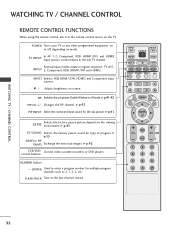
... factory preset sound for the sub-picture. POWER Turns your TV or any other programmed equipment on or off mode. External input modes rotate in regular sequence: TV, AV1INPUT 2, Component, RGB, HDMI1/DVI and HDMI2. Adjusts brightness on the TV. FLASH BACK Tune to the last TV channel. Changes the PIP channel. TV INPUT In AV 1-2, Component, RGB, HDMI1/DVI, and HDMI2 input sources, screen returns to the last channel viewed. control buttons NUMBER button - (DASH) Used to enter a program number...
... factory preset sound for the sub-picture. POWER Turns your TV or any other programmed equipment on or off mode. External input modes rotate in regular sequence: TV, AV1INPUT 2, Component, RGB, HDMI1/DVI and HDMI2. Adjusts brightness on the TV. FLASH BACK Tune to the last TV channel. Changes the PIP channel. TV INPUT In AV 1-2, Component, RGB, HDMI1/DVI, and HDMI2 input sources, screen returns to the last channel viewed. control buttons NUMBER button - (DASH) Used to enter a program number...
Owners Manual
Page 37
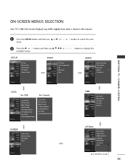
... SCREEN LOCK Auto config. XGA Mode Reset TIME SETUP VIDEO AUDIO TIME OPTION SCREEN LOCK Auto Clock Manual Clock Off Timer On Timer Auto Off OPTION SETUP VIDEO AUDIO TIME OPTION SCREEN LOCK Aspect Ratio Caption/Text Caption Options Language ISM Method Low Power Set ID Only 42PX8DC model 35 or button to display the SETUP SETUP VIDEO AUDIO TIME OPTION SCREEN LOCK EZ Scan Manual Scan Channel Edit DTV Signal Channel Label VIDEO SETUP VIDEO AUDIO TIME OPTION SCREEN LOCK EZ Picture Color Temperature XD Advanced Reset AUDIO SETUP Audio Language VIDEO EZ SoundRite AUDIO EZ Sound...
... SCREEN LOCK Auto config. XGA Mode Reset TIME SETUP VIDEO AUDIO TIME OPTION SCREEN LOCK Auto Clock Manual Clock Off Timer On Timer Auto Off OPTION SETUP VIDEO AUDIO TIME OPTION SCREEN LOCK Aspect Ratio Caption/Text Caption Options Language ISM Method Low Power Set ID Only 42PX8DC model 35 or button to display the SETUP SETUP VIDEO AUDIO TIME OPTION SCREEN LOCK EZ Scan Manual Scan Channel Edit DTV Signal Channel Label VIDEO SETUP VIDEO AUDIO TIME OPTION SCREEN LOCK EZ Picture Color Temperature XD Advanced Reset AUDIO SETUP Audio Language VIDEO EZ SoundRite AUDIO EZ Sound...
Owners Manual
Page 76
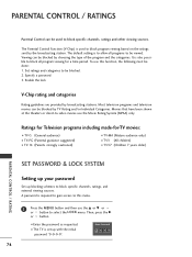
... The default setting is also possible to block specific channels, ratings and other viewing sources. Then, press the G or button. ■ Enter the password as requested. ■ The TV is used to block all programs to block program viewing based on the ratings sent by choosing the type of the program and the categories. Specify a password 3. The Parental Control Function (V-Chip) is set up blocking schemes to select the LOCK menu. Viewing...
... The default setting is also possible to block specific channels, ratings and other viewing sources. Then, press the G or button. ■ Enter the password as requested. ■ The TV is used to block all programs to block program viewing based on the ratings sent by choosing the type of the program and the categories. Specify a password 3. The Parental Control Function (V-Chip) is set up blocking schemes to select the LOCK menu. Viewing...
Owners Manual
Page 78
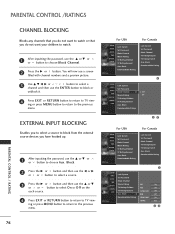
... the external source devices you do not want to watch . 1 After inputting the password, use the D or E or or button to select O n or O f f on the each source. 4 Press EXIT or RETURN button to return to the previous menu. 76 For USA SETUP VIDEO AUDIO TIME OPTION SCREEN LOCK Lock System Set Password Block Channel Movie Rating TV Rating-Children TV Rating-General Aux. You will now see a screen filled with channel numbers...
... the external source devices you do not want to watch . 1 After inputting the password, use the D or E or or button to select O n or O f f on the each source. 4 Press EXIT or RETURN button to return to the previous menu. 76 For USA SETUP VIDEO AUDIO TIME OPTION SCREEN LOCK Lock System Set Password Block Channel Movie Rating TV Rating-Children TV Rating-General Aux. You will now see a screen filled with channel numbers...
Owners Manual
Page 86
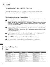
... MENU button to store the code. When pressing the button, the light blinks at the same time for 20 seconds, the light on the mode button will be programmed. If not, steps 2-5. Programming a code into a remote mode 1 To find out whether your remote control can be programmed to see if the device responds properly. If not, the remote should be programmed to repeat from step 2. 3 Enter the appropriate code from the code table...
... MENU button to store the code. When pressing the button, the light blinks at the same time for 20 seconds, the light on the mode button will be programmed. If not, steps 2-5. Programming a code into a remote mode 1 To find out whether your remote control can be programmed to see if the device responds properly. If not, the remote should be programmed to repeat from step 2. 3 Enter the appropriate code from the code table...


