
User Manual
Page 1
See the label attched on the back cover and quote this manual carefully before operating your dealer when you require service. Changing the factory default settings or enabling other features may increase power consumption that ...Consumer User 1-888-865-3026 USA, Commercial User 1-888-542-2623 CANADA LG Customer Information Center P/NO : SAC34026004 (0912-REV00) www.lgcommercial.com Record model number and serial number of the set . LCD TV OWNER'S MANUAL 32LH240H 32LH250H 37LH250H 42LH250H 32LH255H 37LH255H 42LH255H 37LH260H 42LH260H 37LH265H please read this information to quality...
See the label attched on the back cover and quote this manual carefully before operating your dealer when you require service. Changing the factory default settings or enabling other features may increase power consumption that ...Consumer User 1-888-865-3026 USA, Commercial User 1-888-542-2623 CANADA LG Customer Information Center P/NO : SAC34026004 (0912-REV00) www.lgcommercial.com Record model number and serial number of the set . LCD TV OWNER'S MANUAL 32LH240H 32LH250H 37LH250H 42LH250H 32LH255H 37LH255H 42LH255H 37LH260H 42LH260H 37LH265H please read this information to quality...

User Manual
Page 5
... appliance and has no additional outlets or branch circuits. The plug must be connected to be placed upon . Periodically examine the cord of this owner's manual to a three-prong grouned AC outlet) If grounding methods are dangerous. Do not make sure not to install the TV by connecting it , discontinue use...
... appliance and has no additional outlets or branch circuits. The plug must be connected to be placed upon . Periodically examine the cord of this owner's manual to a three-prong grouned AC outlet) If grounding methods are dangerous. Do not make sure not to install the TV by connecting it , discontinue use...
User Manual
Page 7
Color Tone Preset 55 Manual Picture Adjustment - Eye Care 59 Advanced Control - Caption Option 75 TIME SETTING Clock Setting - User Mode ...36 Volume Adjustment 36 On-Screen Menus Selection 37 Channel Setup - Digital Broadcasting System Captions 74 - Add / Delete Channel (Manual Tuning 39 - SRS TruSurround XT 65 Clear Voice II 66 Balance 67 TV Speakers On/Off Setup 68 Audio Reset 69 ... Menus Language Selection 72 Caption Mode - Auto Scan (Auto Tuning 38 - Auto Clock Setup 76 Manual Clock Setup 77 Auto On/Off Time Setting 78 Sleep Timer Setting 79 5
Color Tone Preset 55 Manual Picture Adjustment - Eye Care 59 Advanced Control - Caption Option 75 TIME SETTING Clock Setting - User Mode ...36 Volume Adjustment 36 On-Screen Menus Selection 37 Channel Setup - Digital Broadcasting System Captions 74 - Add / Delete Channel (Manual Tuning 39 - SRS TruSurround XT 65 Clear Voice II 66 Balance 67 TV Speakers On/Off Setup 68 Audio Reset 69 ... Menus Language Selection 72 Caption Mode - Auto Scan (Auto Tuning 38 - Auto Clock Setup 76 Manual Clock Setup 77 Auto On/Off Time Setting 78 Sleep Timer Setting 79 5

User Manual
Page 10
... ENTER CH P A G E RETURN 1 4 MARK RATIO POWER 2 INPUT CC 753 86 LIST 0 9 VOL MUTE FLASHBK ENTER CH P A G E MENU TIMER ALAM RETURN SAP EJECT 1.5V 1.5V Owner's Manual CD Manual Remote Control, Batteries Power Cord Not included with your TV. The accessories included may cause scratch or discoloration.
... ENTER CH P A G E RETURN 1 4 MARK RATIO POWER 2 INPUT CC 753 86 LIST 0 9 VOL MUTE FLASHBK ENTER CH P A G E MENU TIMER ALAM RETURN SAP EJECT 1.5V 1.5V Owner's Manual CD Manual Remote Control, Batteries Power Cord Not included with your TV. The accessories included may cause scratch or discoloration.
User Manual
Page 16
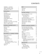
...wall mount is used . Model VESA (A * B) A Standard Screw Quantity B Wall Mounting Bracket (sold separately) 32LH240H, 32LH250H, 200 * 100 M4 4 32LH255H 37LH250H, 37LH255H, 37LH260H, 37LH265H, 200 * 200 M6 4 42LH255H, 42LH260H, 42LH265H .... G Do not use screws that wall mounting be performed by a qualified professional installer. LG is turned on their specifications. PREPARATION PREPARATION VESA WALL MOUNTING Install your nearest installer. NOTE ... our wall mount kit, a detailed installation manual and all parts necessary for wall mount kits are provided.
...wall mount is used . Model VESA (A * B) A Standard Screw Quantity B Wall Mounting Bracket (sold separately) 32LH240H, 32LH250H, 200 * 100 M4 4 32LH255H 37LH250H, 37LH255H, 37LH260H, 37LH265H, 200 * 200 M6 4 42LH255H, 42LH260H, 42LH265H .... G Do not use screws that wall mounting be performed by a qualified professional installer. LG is turned on their specifications. PREPARATION PREPARATION VESA WALL MOUNTING Install your nearest installer. NOTE ... our wall mount kit, a detailed installation manual and all parts necessary for wall mount kits are provided.
User Manual
Page 18
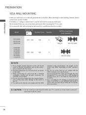
SWIVEL STAND After installing the TV, you can adjust the TV set manually to suit your TV. PREPARATION PREPARATION DESKTOP PEDESTAL INSTALLATION ■ Image shown may differ from the wall. 4 inches 4 inches 4 inches 4 inches CAUTION G Ensure adequate ventilation by 90 degrees to the left or right direction by following the clearance recommendations. For proper ventilation, allow a clearance of heat source. G Do not mount near or above any type of 4 inches on all four sides from your viewing position. 16
SWIVEL STAND After installing the TV, you can adjust the TV set manually to suit your TV. PREPARATION PREPARATION DESKTOP PEDESTAL INSTALLATION ■ Image shown may differ from the wall. 4 inches 4 inches 4 inches 4 inches CAUTION G Ensure adequate ventilation by 90 degrees to the left or right direction by following the clearance recommendations. For proper ventilation, allow a clearance of heat source. G Do not mount near or above any type of 4 inches on all four sides from your viewing position. 16

User Manual
Page 22
... an external digital set -top box.) ■ Select Component input source using the INPUT button on the digital set-top box. (Refer to the owner's manual for the digital set -top box. Component Connection 1. Y PB PR L R 2 Connect the audio output of the digital settop box to the COMPONENT IN VIDEO jacks...
... an external digital set -top box.) ■ Select Component input source using the INPUT button on the digital set-top box. (Refer to the owner's manual for the digital set -top box. Component Connection 1. Y PB PR L R 2 Connect the audio output of the digital settop box to the COMPONENT IN VIDEO jacks...
User Manual
Page 23
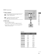
... 59.939 60.00 24.00 23.976 30.00 29.97 21 How to connect 1 Connect the digital set-top box to the owner's manual for the digital set -top box. (Refer to HDMI /DVI IN 1 or HDMI 2 jack on the remote control. EXTERNAL EQUIPMENT SETUP HDMI Connection 1. HDMI supports...
... 59.939 60.00 24.00 23.976 30.00 29.97 21 How to connect 1 Connect the digital set-top box to the owner's manual for the digital set -top box. (Refer to HDMI /DVI IN 1 or HDMI 2 jack on the remote control. EXTERNAL EQUIPMENT SETUP HDMI Connection 1. HDMI supports...

User Manual
Page 24
... a separate audio connection is required for the digital set -top box. (Refer to HDMI Connection 1. EXTERNAL EQUIPMENT SETUP EXTERNAL EQUIPMENT SETUP DVI to the owner's manual for this connection. How to use ■ Turn on the digital set -top box.) ■ Select the HDMI1 input source on the TV using the...
... a separate audio connection is required for the digital set -top box. (Refer to HDMI Connection 1. EXTERNAL EQUIPMENT SETUP EXTERNAL EQUIPMENT SETUP DVI to the owner's manual for this connection. How to use ■ Turn on the digital set -top box.) ■ Select the HDMI1 input source on the TV using the...

User Manual
Page 25
...) R 2 VIDEO L R AUDIO 1 COMPONENT IN R ( /DVI IN SPEAKER OUT REMOTE (8 ) CONTROL O Component Input ports To get better picture quality, connect a DVD player to the DVD player's manual for operating instructions. How to use ■ Turn on the DVD player, insert a DVD. ■ Select the Component input source on the TV using the...
...) R 2 VIDEO L R AUDIO 1 COMPONENT IN R ( /DVI IN SPEAKER OUT REMOTE (8 ) CONTROL O Component Input ports To get better picture quality, connect a DVD player to the DVD player's manual for operating instructions. How to use ■ Turn on the DVD player, insert a DVD. ■ Select the Component input source on the TV using the...

User Manual
Page 26
... 1 Connect the HDMI output of the DVD to the HDMI/DVI IN 1 or HDMI 2 jack on the remote control. ■ Refer to the DVD player's manual for operating instructions. HDMI supports both audio and video. 2. How to use ■ Turn on the DVD player, insert a DVD. ■ Select the or A V 1 input... INPUT button on the remote control. ■ If connected to AV IN 2, select AV2 input source on the TV. ■ Refer to the DVD player's manual for operating instructions. How to connect 1 Connect the AUDIO/VIDEO jacks between TV and DVD.
... 1 Connect the HDMI output of the DVD to the HDMI/DVI IN 1 or HDMI 2 jack on the remote control. ■ Refer to the DVD player's manual for operating instructions. HDMI supports both audio and video. 2. How to use ■ Turn on the DVD player, insert a DVD. ■ Select the or A V 1 input... INPUT button on the remote control. ■ If connected to AV IN 2, select AV2 input source on the TV. ■ Refer to the DVD player's manual for operating instructions. How to connect 1 Connect the AUDIO/VIDEO jacks between TV and DVD.

User Manual
Page 27
... tune TV to the same channel number. ■ Insert a video tape into the VCR and press PLAY on the VCR. (Refer to the VCR owner's manual.) ■ Select the A V 1 input source on the TV using the INPUT button on the remote control. ■ If connected to AV IN 2, select AV2 input.... 2. How to the AUDIO (L/MONO) jack of the VCR to the ANTENNA IN socket on the TV. 2 Connect the antenna cable to the VCR owner's manual.) 1 S-VIDEO VIDEO L R ANT OUT OUTPUT SWITCH ANT IN Wall Jack 2 ANTENNA IN M.P.I. How to connect 1 Connect the RF antenna out socket of the TV. Antenna...
... tune TV to the same channel number. ■ Insert a video tape into the VCR and press PLAY on the VCR. (Refer to the VCR owner's manual.) ■ Select the A V 1 input source on the TV using the INPUT button on the remote control. ■ If connected to AV IN 2, select AV2 input.... 2. How to the AUDIO (L/MONO) jack of the VCR to the ANTENNA IN socket on the TV. 2 Connect the antenna cable to the VCR owner's manual.) 1 S-VIDEO VIDEO L R ANT OUT OUTPUT SWITCH ANT IN Wall Jack 2 ANTENNA IN M.P.I. How to connect 1 Connect the RF antenna out socket of the TV. Antenna...

User Manual
Page 32
...-PC) Enter G Screen Resolution Auto config. G Position Size Phase Reset Move MENU Prev. After adjustment, if the image is still not correct, try using the manual settings or a different resolution or refresh rate on the PC. Select Screen (RGB-PC). 3 ENTER 4 ENTER Select Auto config.. Auto Config.
...-PC) Enter G Screen Resolution Auto config. G Position Size Phase Reset Move MENU Prev. After adjustment, if the image is still not correct, try using the manual settings or a different resolution or refresh rate on the PC. Select Screen (RGB-PC). 3 ENTER 4 ENTER Select Auto config.. Auto Config.

User Manual
Page 33
...; P h a s e: This function allows you prefer. ■ S i z e: This function is not clear after auto adjustment and especially if characters are still trembling, adjust the picture phase manually.
...; P h a s e: This function allows you prefer. ■ S i z e: This function is not clear after auto adjustment and especially if characters are still trembling, adjust the picture phase manually.

User Manual
Page 39
CHANNEL Auto Tuning Manual Tuning Channel Edit Channel Label Move Enter PICTURE Move Aspect Ratio : 16:9 Picture Mode : Standard • Backlight • Contrast • Brightness • Sharpness • Color &#... Display each menu. WATCHING TV / CHANNEL CONTROL ON-SCREEN MENUS SELECTION Your TV's OSD (On Screen Display) may differ slightly from that shown in this manual. USB Photo List Music List Eject Item Move Enter 37 Select a menu item. 3 ENTER Enter to the pop up menu. 4 MENU Return to TV viewing...
CHANNEL Auto Tuning Manual Tuning Channel Edit Channel Label Move Enter PICTURE Move Aspect Ratio : 16:9 Picture Mode : Standard • Backlight • Contrast • Brightness • Sharpness • Color &#... Display each menu. WATCHING TV / CHANNEL CONTROL ON-SCREEN MENUS SELECTION Your TV's OSD (On Screen Display) may differ slightly from that shown in this manual. USB Photo List Music List Eject Item Move Enter 37 Select a menu item. 3 ENTER Enter to the pop up menu. 4 MENU Return to TV viewing...

User Manual
Page 40
Run this function with the antenna connected during Auto Tuning. CHANNEL Auto Tuning Manual Tuning Channel Edit Channel Label Move Enter CHANNEL Auto Tuning Manual Tuning Channel Edit Channel Label Move Enter Check your residence or move the TV. Select Auto Tuning. 3 ENTER Select Y e s. 4 ENTER Run Auto ... antenna or cable inputs, and stores them in the LOCK Menu to allow a channel search. ■ When setting the Auto tuning or Manual tuning, the number of maximum channel you change your antenna connection. Also, make sure to run this function if you can store is subject...
Run this function with the antenna connected during Auto Tuning. CHANNEL Auto Tuning Manual Tuning Channel Edit Channel Label Move Enter CHANNEL Auto Tuning Manual Tuning Channel Edit Channel Label Move Enter Check your residence or move the TV. Select Auto Tuning. 3 ENTER Select Y e s. 4 ENTER Run Auto ... antenna or cable inputs, and stores them in the LOCK Menu to allow a channel search. ■ When setting the Auto tuning or Manual tuning, the number of maximum channel you change your antenna connection. Also, make sure to run this function if you can store is subject...

User Manual
Page 41
...39 ENTER Select A d d or D e l e t e. 6 RETURN Return to add or delete. Return to allow a channel search. ■ When setting the Auto tuning or Manual tuning, the number of the signal being received. Use the password you set up in the LOCK Menu to TV viewing. It is 1000. CHANNEL... Auto Tuning Manual Tuning Channel Edit Channel Label Move Enter 1 MENU 2 ENTER Select CHANNEL. Channel 2 DIGITAL 2-1 Bad Normal Good Delete Close ■ The TV ...
...39 ENTER Select A d d or D e l e t e. 6 RETURN Return to add or delete. Return to allow a channel search. ■ When setting the Auto tuning or Manual tuning, the number of the signal being received. Use the password you set up in the LOCK Menu to TV viewing. It is 1000. CHANNEL... Auto Tuning Manual Tuning Channel Edit Channel Label Move Enter 1 MENU 2 ENTER Select CHANNEL. Channel 2 DIGITAL 2-1 Bad Normal Good Delete Close ■ The TV ...

User Manual
Page 42
CHANNEL Auto Tuning Manual Tuning Channel Edit Channel Label Move Enter Ch. RETURN 40 WATCHING TV / CHANNEL CONTROL WATCHING TV / CHANNEL CONTROL Channel Editing The channels in the Channel ...
CHANNEL Auto Tuning Manual Tuning Channel Edit Channel Label Move Enter Ch. RETURN 40 WATCHING TV / CHANNEL CONTROL WATCHING TV / CHANNEL CONTROL Channel Editing The channels in the Channel ...
User Manual
Page 43
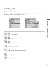
... name for a channel even if you didn't preset a label for the channel. 6 RETURN Return to TV viewing. CHANNEL Auto Tuning Manual Tuning Channel Edit Channel Label Move Enter CHANNEL Auto Tuning Manual Tuning Channel Edit Channel Label Move Enter Channel DIGITAL 2-1 Logo F Disney G Close WATCHING TV / CHANNEL CONTROL 1 MENU 2 ENTER 3 ENTER Select...
... name for a channel even if you didn't preset a label for the channel. 6 RETURN Return to TV viewing. CHANNEL Auto Tuning Manual Tuning Channel Edit Channel Label Move Enter CHANNEL Auto Tuning Manual Tuning Channel Edit Channel Label Move Enter Channel DIGITAL 2-1 Logo F Disney G Close WATCHING TV / CHANNEL CONTROL 1 MENU 2 ENTER 3 ENTER Select...

User Manual
Page 46
.... G Only use only a USB storage device which was formatted as a different utility programme which requires an external power supply. G Please connect power to the user manual of a USB storage device may not work , turn off and on the USB device may not be recognized. If not, the device may be deleted...
.... G Only use only a USB storage device which was formatted as a different utility programme which requires an external power supply. G Please connect power to the user manual of a USB storage device may not work , turn off and on the USB device may not be recognized. If not, the device may be deleted...


