
Owners Manual
Page 3
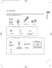
... you purchased the product. User Guide TINVPUT INPUT ARC POWER EXIT LIST PIP TEXT PR- INDEX 9 FAV Owner's Manual Batteries Remote Control Power Cord For 42PC1RV*, 42PC3RV* 2-Wall brackets 2-eye-bolts For 26LC2R*, 32LC2R* 2-bolts for stand assembly 2-bolts 1 Cable Management 32LC2R* only 4-bolts for stand assembly Refer to p.12 2-TV brackets 2-Wall...
... you purchased the product. User Guide TINVPUT INPUT ARC POWER EXIT LIST PIP TEXT PR- INDEX 9 FAV Owner's Manual Batteries Remote Control Power Cord For 42PC1RV*, 42PC3RV* 2-Wall brackets 2-eye-bolts For 26LC2R*, 32LC2R* 2-bolts for stand assembly 2-bolts 1 Cable Management 32LC2R* only 4-bolts for stand assembly Refer to p.12 2-TV brackets 2-Wall...

Owners Manual
Page 4
... . . .61 Low Power 62 XD Demo 63 0323G_1-en_rev01 2/28/06 4:12 PM Page 2 CONTENTS CONTENTS ACCESSORIES 1 INTRODUCTION Controls / Connection Options 4-9 Remote Control Key Functions 10-11 Installing Batteries 11 INSTALLATION Stand Installation 12-13 Basic Connection / How to Remove the Cable Management 14-15 How... Menu Options PSM (Picture Status Memory) 42 Picture Adjustment (PSM-User option 43 CSM (Colour Status Memory 44 Manual Colour Temperature Control (CSM - User option 45 Function 46 ADVANCED-CINEMA 47 ADVANCED-BLACK LEVEL 48 Reset 49 Sound Menu Options SSM (Sound Status...
... . . .61 Low Power 62 XD Demo 63 0323G_1-en_rev01 2/28/06 4:12 PM Page 2 CONTENTS CONTENTS ACCESSORIES 1 INTRODUCTION Controls / Connection Options 4-9 Remote Control Key Functions 10-11 Installing Batteries 11 INSTALLATION Stand Installation 12-13 Basic Connection / How to Remove the Cable Management 14-15 How... Menu Options PSM (Picture Status Memory) 42 Picture Adjustment (PSM-User option 43 CSM (Colour Status Memory 44 Manual Colour Temperature Control (CSM - User option 45 Function 46 ADVANCED-CINEMA 47 ADVANCED-BLACK LEVEL 48 Reset 49 Sound Menu Options SSM (Sound Status...
Owners Manual
Page 5
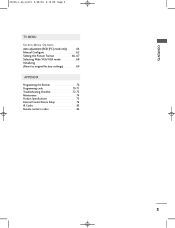
CONTENTS 0323G_1-en_rev01 2/28/06 4:12 PM Page 3 TV MENU Screen Menu Options Auto adjustment (RGB [PC] mode only 64 Manual Configure 65 Setting the Picture Format 66-67 Selecting Wide VGA/XGA mode 68 Initializing (Reset to original factory settings 69 APPENDIX Programming the Remote 70 Programming code 70-71 Troubleshooting Checklist 72-73 Maintenance 74 Product Specifications 75 External Control Device Setup 76 IR Codes 83 Remote control ir codes 84 3
CONTENTS 0323G_1-en_rev01 2/28/06 4:12 PM Page 3 TV MENU Screen Menu Options Auto adjustment (RGB [PC] mode only 64 Manual Configure 65 Setting the Picture Format 66-67 Selecting Wide VGA/XGA mode 68 Initializing (Reset to original factory settings 69 APPENDIX Programming the Remote 70 Programming code 70-71 Troubleshooting Checklist 72-73 Maintenance 74 Product Specifications 75 External Control Device Setup 76 IR Codes 83 Remote control ir codes 84 3
Owners Manual
Page 7
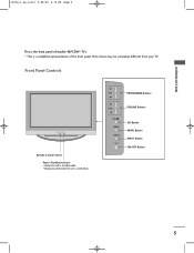
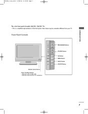
Here shown may be somewhat different from your TV. Front Panel Controls Remote Control Sensor Power/Standby Indicator • illuminates red in standby mode. • illuminates white when the set is a simplified representation of models 42PC3RV* TVs. PR PROGRAMME Buttons VOL VOLUME Buttons OK MENU INPUT OK Button MENU Button INPUT Button ON/OFF Button 5 I This is switched on. INTRODUCTION 0323G_1-en_rev01 2/28/06 4:12 PM Page 5 This is the front panel of the front panel.
Here shown may be somewhat different from your TV. Front Panel Controls Remote Control Sensor Power/Standby Indicator • illuminates red in standby mode. • illuminates white when the set is a simplified representation of models 42PC3RV* TVs. PR PROGRAMME Buttons VOL VOLUME Buttons OK MENU INPUT OK Button MENU Button INPUT Button ON/OFF Button 5 I This is switched on. INTRODUCTION 0323G_1-en_rev01 2/28/06 4:12 PM Page 5 This is the front panel of the front panel.
Owners Manual
Page 8
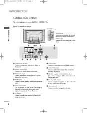
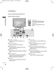
... to the RS-232C jack. 10 Variable Audio Output Connect an external amplifier or add a subwoofer to your wired remote control here. 3 RGB/Audio Input Connect the monitor output from an external device. 0323G_1-en_rev01 2/28/06 4:12 PM Page 6 INTRODUCTION INTRODUCTION CONNECTION ... 7 S-Video Input Connect S-Video out from an S-VIDEO device. 8 Audio/Video Input Connect audio/video output from an external device to these jacks. 2 Remote Control Port Connect your surround sound system. 11 Antenna Input Connect over-the-air signals to HDMI port with HDMI cable. 5 Power Cord Socket This TV...
... to the RS-232C jack. 10 Variable Audio Output Connect an external amplifier or add a subwoofer to your wired remote control here. 3 RGB/Audio Input Connect the monitor output from an external device. 0323G_1-en_rev01 2/28/06 4:12 PM Page 6 INTRODUCTION INTRODUCTION CONNECTION ... 7 S-Video Input Connect S-Video out from an S-VIDEO device. 8 Audio/Video Input Connect audio/video output from an external device to these jacks. 2 Remote Control Port Connect your surround sound system. 11 Antenna Input Connect over-the-air signals to HDMI port with HDMI cable. 5 Power Cord Socket This TV...
Owners Manual
Page 9
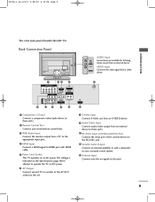
VOL OK MENU INPUT /I This is a simplified representation of models 26LC2R*, 32LC2R* TVs. Here shown may be somewhat different from your TV. Front Panel Controls PR R Remote Control Sensor Power/Standby Indicator • illuminates red in standby mode. • illuminates white when the set is the front panel of the front panel. I PROGRAMME Buttons VOLUME Buttons OK Button MENU Button INPUT Button ON/OFF Button 7 INTRODUCTION 0323G_1-en_rev01 2/28/06 4:12 PM Page 7 This is switched on.
VOL OK MENU INPUT /I This is a simplified representation of models 26LC2R*, 32LC2R* TVs. Here shown may be somewhat different from your TV. Front Panel Controls PR R Remote Control Sensor Power/Standby Indicator • illuminates red in standby mode. • illuminates white when the set is the front panel of the front panel. I PROGRAMME Buttons VOLUME Buttons OK Button MENU Button INPUT Button ON/OFF Button 7 INTRODUCTION 0323G_1-en_rev01 2/28/06 4:12 PM Page 7 This is switched on.
Owners Manual
Page 10
...Input Connect S-Video out from an S-VIDEO device. 8 Audio/Video Input Connect audio/video output from an external device to these jacks. 2 Remote Control Port Connect your surround sound system. 11 Antenna Input Connect over-the-air signals to HDMI port with HDMI cable. 5 Power Cord Socket This... 26LC2R* TVs. 0323G_1-en_rev01 2/28/06 4:12 PM Page 8 INTRODUCTION CONTROLS This is indicated on an AC power. The voltage is the back panel of the control devices to the RS-232C jack. 10 Variable Audio Output Connect an external amplifier or add a subwoofer to your wired remote control here...
...Input Connect S-Video out from an S-VIDEO device. 8 Audio/Video Input Connect audio/video output from an external device to these jacks. 2 Remote Control Port Connect your surround sound system. 11 Antenna Input Connect over-the-air signals to HDMI port with HDMI cable. 5 Power Cord Socket This... 26LC2R* TVs. 0323G_1-en_rev01 2/28/06 4:12 PM Page 8 INTRODUCTION CONTROLS This is indicated on an AC power. The voltage is the back panel of the control devices to the RS-232C jack. 10 Variable Audio Output Connect an external amplifier or add a subwoofer to your wired remote control here...
Owners Manual
Page 11
... to the RS-232C jack. 10 Variable Audio Output Connect an external amplifier or add a subwoofer to your wired remote control here. 3 RGB/Audio Input Connect the monitor output from a PC to the appropriate input port. 4 HDMI Input Connect a HDMI signal to this jack. 9 Never... AC power. Back Connection Panel AC IN AUDIO Input R Connections are available for listening AUDIO stereo sound from an external device to these jacks. 2 Remote Control Port Connect your surround sound system. 11 Antenna Input Connect over-the-air signals to HDMI port with HDMI cable. 5 Power Cord Socket This TV...
... to the RS-232C jack. 10 Variable Audio Output Connect an external amplifier or add a subwoofer to your wired remote control here. 3 RGB/Audio Input Connect the monitor output from a PC to the appropriate input port. 4 HDMI Input Connect a HDMI signal to this jack. 9 Never... AC power. Back Connection Panel AC IN AUDIO Input R Connections are available for listening AUDIO stereo sound from an external device to these jacks. 2 Remote Control Port Connect your surround sound system. 11 Antenna Input Connect over-the-air signals to HDMI port with HDMI cable. 5 Power Cord Socket This TV...
Owners Manual
Page 12
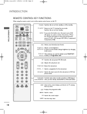
... the input source for the sub picture. 0323G_1-en_rev01 2/28/06 4:12 PM Page 10 INTRODUCTION INTRODUCTION REMOTE CONTROL KEY FUNCTIONS When using the remote control, aim it at the remote control sensor on -screen displays and returns to the TV viewing from any menu. Coloured These buttons are used...viewing from standby. PIP Switches the sub picture PIP, DW mode. POSITION Moves the sub picture. VCR/DVD Controls some video cassette recorders or DVD players control buttons when you press the button once, the input source OSD will appear on from any mode. MENU Selects ...
... the input source for the sub picture. 0323G_1-en_rev01 2/28/06 4:12 PM Page 10 INTRODUCTION INTRODUCTION REMOTE CONTROL KEY FUNCTIONS When using the remote control, aim it at the remote control sensor on -screen displays and returns to the TV viewing from any menu. Coloured These buttons are used...viewing from standby. PIP Switches the sub picture PIP, DW mode. POSITION Moves the sub picture. VCR/DVD Controls some video cassette recorders or DVD players control buttons when you press the button once, the input source OSD will appear on from any mode. MENU Selects ...
Owners Manual
Page 21
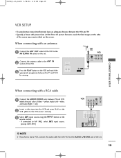
... for viewing. AV IN 3 S-VIDEO VIDEO ( ) AUDIO 19 1 2 If connected to the VCR owner's manual.) 3 Select AV1 input source using the INPUT button on the remote control. - HDMI/DVI IN VARIABLE AUDIO OUT ANTENNA IN 2 VCR ANT IN 34 IN ANT OUT S-VIDEO OUT OUTPUT SWITCH (R) AUDIO (L) VIDEO 1 When connecting with an...
... for viewing. AV IN 3 S-VIDEO VIDEO ( ) AUDIO 19 1 2 If connected to the VCR owner's manual.) 3 Select AV1 input source using the INPUT button on the remote control. - HDMI/DVI IN VARIABLE AUDIO OUT ANTENNA IN 2 VCR ANT IN 34 IN ANT OUT S-VIDEO OUT OUTPUT SWITCH (R) AUDIO (L) VIDEO 1 When connecting with an...
Owners Manual
Page 22
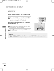
... improved; CONNECTIONS & SETUP 20 0323G_1-en_rev01 2/28/06 4:12 PM Page 20 CONNECTIONS & SETUP VCR SETUP When connecting with using the INPUT button on the remote control. compared to normal composite (RCA cable) input. 2 Connect the audio outputs of the VCR to the AUDIO input jacks on the set .
... improved; CONNECTIONS & SETUP 20 0323G_1-en_rev01 2/28/06 4:12 PM Page 20 CONNECTIONS & SETUP VCR SETUP When connecting with using the INPUT button on the remote control. compared to normal composite (RCA cable) input. 2 Connect the audio outputs of the VCR to the AUDIO input jacks on the set .
Owners Manual
Page 23
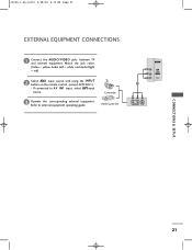
Match the jack colors (Video = yellow, Audio Left = white, and Audio Right = red) 2 Select AV2 input source with using the INPUT button on the remote control. (except 42PC3RV*) - Refer to AV IN1 input, select AV1input source. If connected to external equipment operating guide. Video Game Set AV IN 2 R AUDIO L/MONO VIDEO 1 R AUDIO L VIDEO CONNECTIONS & SETUP 21 0323G_1-en_rev01 2/28/06 4:12 PM Page 21 EXTERNAL EQUIPMENT CONNECTIONS 1 Connect the AUDIO/VIDEO jacks between TV and external equipment. Camcorder 3 Operate the corresponding external equipment.
Match the jack colors (Video = yellow, Audio Left = white, and Audio Right = red) 2 Select AV2 input source with using the INPUT button on the remote control. (except 42PC3RV*) - Refer to AV IN1 input, select AV1input source. If connected to external equipment operating guide. Video Game Set AV IN 2 R AUDIO L/MONO VIDEO 1 R AUDIO L VIDEO CONNECTIONS & SETUP 21 0323G_1-en_rev01 2/28/06 4:12 PM Page 21 EXTERNAL EQUIPMENT CONNECTIONS 1 Connect the AUDIO/VIDEO jacks between TV and external equipment. Camcorder 3 Operate the corresponding external equipment.
Owners Manual
Page 24
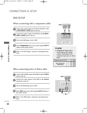
...on the set . 3 Turn on the DVD player, insert a DVD. 4 Select AV3 input source with using the INPUT button on the remote control. 5 Refer to the DVD player's manual for operating instructions. 0323G_1-en_rev01 2/28/06 4:12 PM Page 22 CONNECTIONS & SETUP DVD SETUP ... the AUDIO input jacks on the set . 3 Turn on the DVD player, insert a DVD. 4 Select Component input source with using the INPUT button on the remote control. 5 Refer to the DVD player's manual for operating instructions. When connecting with a S-Video cable DVD B R (R) AUDIO (L) 1 2 COMPONENT IN VIDEO AUDIO ...
...on the set . 3 Turn on the DVD player, insert a DVD. 4 Select AV3 input source with using the INPUT button on the remote control. 5 Refer to the DVD player's manual for operating instructions. 0323G_1-en_rev01 2/28/06 4:12 PM Page 22 CONNECTIONS & SETUP DVD SETUP ... the AUDIO input jacks on the set . 3 Turn on the DVD player, insert a DVD. 4 Select Component input source with using the INPUT button on the remote control. 5 Refer to the DVD player's manual for operating instructions. When connecting with a S-Video cable DVD B R (R) AUDIO (L) 1 2 COMPONENT IN VIDEO AUDIO ...
Owners Manual
Page 25
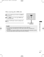
...with using a HDMI cable. tions. NOTE G TV can receive the video and audio signal simultaneously with using the INPUT button on the remote control. G If the DVD supports Auto HDMI function, the DVD output resolution will be automatically set the output resolution appropriately. VIDEO AUDIO RGB ...IN (PC/DTV) HDMI IN REMOTE AUDIO IN CONTROL IN (RGB) VARIABLE AUDIO OUT RS-232C IN (CONTROL&SERVICE) 1 DVD HDMI-DVD OUTPUT ! G If the DVD does not support Auto HDMI, you need to...
...with using a HDMI cable. tions. NOTE G TV can receive the video and audio signal simultaneously with using the INPUT button on the remote control. G If the DVD supports Auto HDMI function, the DVD output resolution will be automatically set the output resolution appropriately. VIDEO AUDIO RGB ...IN (PC/DTV) HDMI IN REMOTE AUDIO IN CONTROL IN (RGB) VARIABLE AUDIO OUT RS-232C IN (CONTROL&SERVICE) 1 DVD HDMI-DVD OUTPUT ! G If the DVD does not support Auto HDMI, you need to...

Owners Manual
Page 26
... set-top box. (Refer to the owner's manual for the digital set-top box.) 4 Select HDMI input source with using the INPUT button on the remote control. Digital Set-top Box B R (R) AUDIO (L) 1 2 COMPONENT IN VIDEO AUDIO 1 2 AV OUT ( MONO) S-VIDEO VIDEO AUDIO AV IN 1 CONNECTIONS ...top box.) 4 Select Component input source with using the INPUT button on the remote control. 1 2 AV IN 1 S-VIDEO VIDEO ( ) AUDIO RGB IN (PC/DTV) HDMI IN REMOTE AUDIO IN CONTROL IN (RGB) VARIABLE AUDIO OUT RS-232C IN (CONTROL&SERVICE) 1 2 Digital Set-top Box DVI-DTV OUTPUT (R) AUDIO (L) !...
... set-top box. (Refer to the owner's manual for the digital set-top box.) 4 Select HDMI input source with using the INPUT button on the remote control. Digital Set-top Box B R (R) AUDIO (L) 1 2 COMPONENT IN VIDEO AUDIO 1 2 AV OUT ( MONO) S-VIDEO VIDEO AUDIO AV IN 1 CONNECTIONS ...top box.) 4 Select Component input source with using the INPUT button on the remote control. 1 2 AV IN 1 S-VIDEO VIDEO ( ) AUDIO RGB IN (PC/DTV) HDMI IN REMOTE AUDIO IN CONTROL IN (RGB) VARIABLE AUDIO OUT RS-232C IN (CONTROL&SERVICE) 1 2 Digital Set-top Box DVI-DTV OUTPUT (R) AUDIO (L) !...
Owners Manual
Page 27
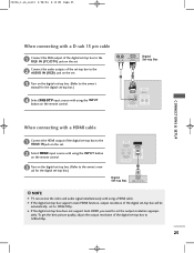
... box.) 4 Select RGB-DTV input source with using the INPUT button on the remote control. (R) AUDIO (L) RGB-DTV OUTPUT Digital Set-top Box 2 1 RGB IN (PC/DTV) HDMI IN REMOTE AUDIO IN CONTROL IN (RGB) VARIABLE AUDIO OUT RS-232C IN (CONTROL&SERVICE) CONNECTIONS & SETUP When connecting with using a HDMI cable. G If the digital set...
... box.) 4 Select RGB-DTV input source with using the INPUT button on the remote control. (R) AUDIO (L) RGB-DTV OUTPUT Digital Set-top Box 2 1 RGB IN (PC/DTV) HDMI IN REMOTE AUDIO IN CONTROL IN (RGB) VARIABLE AUDIO OUT RS-232C IN (CONTROL&SERVICE) CONNECTIONS & SETUP When connecting with using a HDMI cable. G If the digital set...
Owners Manual
Page 28
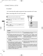
... using 640x480, 60Hz (42PC1RV*, 42PC3RV*) /1024x768, 60Hz (26LC2R*, 32LC2R*) for a long period of time. The fixed image may become permanently imprinted on the remote control. (R) AUDIO (L) RGB-DTV OUTPUT PC 2 1 RGB IN (PC/DTV) HDMI IN REMOTE AUDIO IN CONTROL IN (RGB) VARIABLE AUDIO OUT RS-232C IN (CONTROL&SERVICE) CONNECTIONS & SETUP ! change the PC graphic...
... using 640x480, 60Hz (42PC1RV*, 42PC3RV*) /1024x768, 60Hz (26LC2R*, 32LC2R*) for a long period of time. The fixed image may become permanently imprinted on the remote control. (R) AUDIO (L) RGB-DTV OUTPUT PC 2 1 RGB IN (PC/DTV) HDMI IN REMOTE AUDIO IN CONTROL IN (RGB) VARIABLE AUDIO OUT RS-232C IN (CONTROL&SERVICE) CONNECTIONS & SETUP ! change the PC graphic...
Owners Manual
Page 30
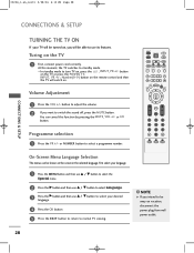
... its features. button to adjust the volume. 2 If you want to normal TV viewing. ! PIP PR+ PIP INPUT LIST MENU I /II button. Turing on the remote control and then the TV will be able to standby mode. REVEAL INDEX On-Screen Menu Language Selection The menus can cancel this moment, the TV...
... its features. button to adjust the volume. 2 If you want to normal TV viewing. ! PIP PR+ PIP INPUT LIST MENU I /II button. Turing on the remote control and then the TV will be able to standby mode. REVEAL INDEX On-Screen Menu Language Selection The menus can cancel this moment, the TV...

Owners Manual
Page 62
...8:57 PM Page 60 TV MENU Special Menu Options CHILD LOCK The TV can be set so that the remote control is turned off . 1 Press the MENU button and then D / E button to select the Special ...feature can be used to prevent unauthorized viewing. NOTE G In Child lock 'O n', if the set is needed to control it was last set to even if you turn the set off , press the r / I /II EXIT SLEEP ...MENU 1 G On Off DE F G OK MENU 23 TV MENU ! TEXT PIP SIZE POSTION PIP PR- button on the remote control. This set is pressed while viewing the set or POWER, INPUT, T V, PR + / - G With the Child ...
...8:57 PM Page 60 TV MENU Special Menu Options CHILD LOCK The TV can be set so that the remote control is turned off . 1 Press the MENU button and then D / E button to select the Special ...feature can be used to prevent unauthorized viewing. NOTE G In Child lock 'O n', if the set is needed to control it was last set to even if you turn the set off , press the r / I /II EXIT SLEEP ...MENU 1 G On Off DE F G OK MENU 23 TV MENU ! TEXT PIP SIZE POSTION PIP PR- button on the remote control. This set is pressed while viewing the set or POWER, INPUT, T V, PR + / - G With the Child ...

Owners Manual
Page 72
... lighted. 3 Press the MENU and MUTE buttons simultaneously, the remote control is ready to be programmed, then press the corresponding mode button (such as a D V D or V C R) on the remote control. Programming a code into a remote mode 1 Test your remote control can operate the component without pro-gramming, turn off. 5 ... pointing at the component. To find out whether your remote control. APPENDIX PROGRAMMING CODE DVD Brand Codes Brand APEX DIGITAL 022 DENON 020 014 GE 005 006 HARMAN KARDON 027 JVC 012 LG 001 010 016 025 MAGNAVOX 013 MARANTZ 024 MITSUBISHI NAD ...
... lighted. 3 Press the MENU and MUTE buttons simultaneously, the remote control is ready to be programmed, then press the corresponding mode button (such as a D V D or V C R) on the remote control. Programming a code into a remote mode 1 Test your remote control can operate the component without pro-gramming, turn off. 5 ... pointing at the component. To find out whether your remote control. APPENDIX PROGRAMMING CODE DVD Brand Codes Brand APEX DIGITAL 022 DENON 020 014 GE 005 006 HARMAN KARDON 027 JVC 012 LG 001 010 016 025 MAGNAVOX 013 MARANTZ 024 MITSUBISHI NAD ...


