FS-1028MFP/1128MFP Operation Guide Rev-3
Page 22
..., THE MFP. Replacement Maintenance Kits have no obligation to operator negligence, misuse, accidents, improper storage or unusual physical or electrical stress, (b) have used parts or supplies which vary from date of purchase. If the Kyocera Dealer is valid only for a period of Kyocera. Warranty (USA) FS-1028MFP/FS-1128MFP MULTIFUNCTIONAL PRODUCT LIMITED WARRANTY Kyocera Mita America, Inc...
..., THE MFP. Replacement Maintenance Kits have no obligation to operator negligence, misuse, accidents, improper storage or unusual physical or electrical stress, (b) have used parts or supplies which vary from date of purchase. If the Kyocera Dealer is valid only for a period of Kyocera. Warranty (USA) FS-1028MFP/FS-1128MFP MULTIFUNCTIONAL PRODUCT LIMITED WARRANTY Kyocera Mita America, Inc...
FS-1028MFP/1128MFP Operation Guide Rev-3
Page 354
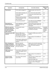
...×400dpi Super Fine when sending an image. - Clean the charger wire. Reference Page - 3-2 2-5 2-5 3-2 7-19 - KYOCERA COMMAND CENTER Operation Guide 8-145 - 5-14 - 8-145 9-5 - - 10-4 OPERATION GUIDE USB memory not recognized. Corrective Actions ...driver and application software settings are printed improperly. Is the USB host blocked? The inside of the drum unit is shrunk vertically or horizontally. Connect the correct printer cable securely. Press [Resume] (the... the toner container and if necessary replace. Check the main charger cleaner of the machine may be dirty.
...×400dpi Super Fine when sending an image. - Clean the charger wire. Reference Page - 3-2 2-5 2-5 3-2 7-19 - KYOCERA COMMAND CENTER Operation Guide 8-145 - 5-14 - 8-145 9-5 - - 10-4 OPERATION GUIDE USB memory not recognized. Corrective Actions ...driver and application software settings are printed improperly. Is the USB host blocked? The inside of the drum unit is shrunk vertically or horizontally. Connect the correct printer cable securely. Press [Resume] (the... the toner container and if necessary replace. Check the main charger cleaner of the machine may be dirty.

Service Manual
Page 9
... wire to the instruction handbook are clean and not peeling. • Do not remove the ozone filter, if any, from the copier except for routine replacement Do not pull on the AC power cord or connector wires on or trapped. Special attention should be present on . Toner may cause sparks when...; Should smoke be seen coming from the copier, remove the power plug from the wall outlet immediately...3.Miscellaneous WARNING • Never attempt to heat the drum or expose it with care by following the instructions below Use only a small amount of solvent at a time, being careful not to spill...
... wire to the instruction handbook are clean and not peeling. • Do not remove the ozone filter, if any, from the copier except for routine replacement Do not pull on the AC power cord or connector wires on or trapped. Special attention should be present on . Toner may cause sparks when...; Should smoke be seen coming from the copier, remove the power plug from the wall outlet immediately...3.Miscellaneous WARNING • Never attempt to heat the drum or expose it with care by following the instructions below Use only a small amount of solvent at a time, being careful not to spill...
Service Manual
Page 12
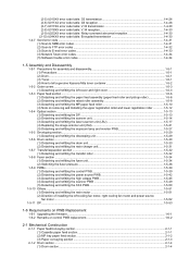
...Software trouble error codes ...1-4-34 1-5 Assembly and Disassembly 1-5-1 Precautions for assembly and disassembly 1-5-1 (1) Precautions ...1-5-1 (2) Drum...1-5-1 (3) Toner ...1-5-1 (4) How to tell a genuine Kyocera Mita toner container 1-5-2 1-5-2 Outer covers ...1-5-3 (1) Detaching and refitting the left cover and right cover 1-5-3 1-5-3 ...(2) Detaching and refitting the scanner unit 1-5-14 (3) Detaching and refitting the laser scanner unit (LSU 1-5-17 (4) Replacing the image scanner unit (ISU 1-5-21 (5) Detaching and refitting the exposure lamp and inverter PWB 1-5-27 1-5-5 Developing...
...Software trouble error codes ...1-4-34 1-5 Assembly and Disassembly 1-5-1 Precautions for assembly and disassembly 1-5-1 (1) Precautions ...1-5-1 (2) Drum...1-5-1 (3) Toner ...1-5-1 (4) How to tell a genuine Kyocera Mita toner container 1-5-2 1-5-2 Outer covers ...1-5-3 (1) Detaching and refitting the left cover and right cover 1-5-3 1-5-3 ...(2) Detaching and refitting the scanner unit 1-5-14 (3) Detaching and refitting the laser scanner unit (LSU 1-5-17 (4) Replacing the image scanner unit (ISU 1-5-21 (5) Detaching and refitting the exposure lamp and inverter PWB 1-5-27 1-5-5 Developing...

Service Manual
Page 58
... off and on. Description U100 Setting the main high voltage Description Controls the main charger high voltage to clear the drum drive time during maintenance service (replacing the maintenance kit). (See page 2-4-4, page 1-5-29 and page 1-5-30) Method 1. Turn the main power switch off...Press the start key. Completion Press the stop key. Change the setting value using the cursor up/down keys. 2. Display Description TIME(min) Drum drive time Clearing 1. Press the start key. Setting 1. Also to optimize the surface potential. Press the start key. 2. The value is...
... off and on. Description U100 Setting the main high voltage Description Controls the main charger high voltage to clear the drum drive time during maintenance service (replacing the maintenance kit). (See page 2-4-4, page 1-5-29 and page 1-5-30) Method 1. Turn the main power switch off...Press the start key. Completion Press the stop key. Change the setting value using the cursor up/down keys. 2. Display Description TIME(min) Drum drive time Clearing 1. Press the start key. Setting 1. Also to optimize the surface potential. Press the start key. 2. The value is...

Service Manual
Page 59
... when a faulty image (black line, etc.) occurs. Press the start key. 5. Purpose To operate when installing the machine or replacing the developing unit. Turn the main power switch off and on . The screen for the developing unit Description Replenishes toner to the developing... unit to a certain level from the toner container that has been installed. is set . 4. Description U113 Performing drum refresh operation Description Sets the drum refresh operation. Change the setting value using the cursor up /down keys and press the start key. 2JN-2 Maintenance ...
... when a faulty image (black line, etc.) occurs. Press the start key. 5. Purpose To operate when installing the machine or replacing the developing unit. Turn the main power switch off and on . The screen for the developing unit Description Replenishes toner to the developing... unit to a certain level from the toner container that has been installed. is set . 4. Description U113 Performing drum refresh operation Description Sets the drum refresh operation. Change the setting value using the cursor up /down keys and press the start key. 2JN-2 Maintenance ...

Service Manual
Page 60
... TIME(min) Developing drive time Completion Press the stop key. Setting 1. Turn the main power switch off and on the drum after low density copying. U157 Checking the developing drive time Description Displays the developing drive time for the number of pages set...to 100 2 0 to be set using the cursor left/right keys. Description U144 Setting toner loading operation Description Sets toner loading operation after replacing the developing unit. Press the start key. Change the setting using the cursor up/down keys. 3. Normally no change is displayed. 1-3-32...
... TIME(min) Developing drive time Completion Press the stop key. Setting 1. Turn the main power switch off and on the drum after low density copying. U157 Checking the developing drive time Description Displays the developing drive time for the number of pages set...to 100 2 0 to be set using the cursor left/right keys. Description U144 Setting toner loading operation Description Sets toner loading operation after replacing the developing unit. Press the start key. Change the setting using the cursor up/down keys. 3. Normally no change is displayed. 1-3-32...
Service Manual
Page 128
... connector. Waste toner full The waste toner sensor has detected that the waste toner reservoir (drum unit) is full. Waste toner reservoir (drum unit) is full. Replace the waste toner sensor. Defective control PWB. Operation panel PWB communication error Defective harness between high...wire Input from fuser thermistor is not resolved, replace the drum unit (See page 1-5-30). Replace the fuser unit (See page 1-5-34). out triggered. Replace the power source PWB (See page 1-5-42). If none, remedy or replace the harness. Fuser thermal cut- Defective harness...
... connector. Waste toner full The waste toner sensor has detected that the waste toner reservoir (drum unit) is full. Waste toner reservoir (drum unit) is full. Replace the waste toner sensor. Defective control PWB. Operation panel PWB communication error Defective harness between high...wire Input from fuser thermistor is not resolved, replace the drum unit (See page 1-5-30). Replace the fuser unit (See page 1-5-34). out triggered. Replace the power source PWB (See page 1-5-42). If none, remedy or replace the harness. Fuser thermal cut- Defective harness...
Service Manual
Page 131
...Defective main charging output. Check the high voltage PWB visually and correct or replace if necessary (See page 1-5-45). Replace the laser scanner unit (See page 1-5-17). Open the front cover and check that the drum unit and developing unit are correctly seated (See page 1-5-30 and 1-5-29...). DP DP connector Defective drum unit or developing unit. Replace the high voltage PWB (See page 1-5-45). Print example Causes Check ...
...Defective main charging output. Check the high voltage PWB visually and correct or replace if necessary (See page 1-5-45). Replace the laser scanner unit (See page 1-5-17). Open the front cover and check that the drum unit and developing unit are correctly seated (See page 1-5-30 and 1-5-29...). DP DP connector Defective drum unit or developing unit. Replace the high voltage PWB (See page 1-5-45). Print example Causes Check ...
Service Manual
Page 132
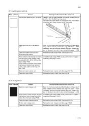
.../16" (See page 2-4-3), the problem may be the damaged heat roller or press roller (in the developing unit). Replace the developing unit or drum unit (See page 1-5-29 or 1-5-30). (5) Black horizontal streaks. Check procedures/corrective measures Check that satisfies the paper specifications.../3 1/16" (See page 2-4-3), the problem may be supported by the bushes at random intervals, the toner may be the damaged drum (in good contact. Replace the drum unit (See page 1-5-30). If the defects occur at regular intervals of electroconductive grease as required. 2JN (3) Dropouts...
.../16" (See page 2-4-3), the problem may be the damaged heat roller or press roller (in the developing unit). Replace the developing unit or drum unit (See page 1-5-29 or 1-5-30). (5) Black horizontal streaks. Check procedures/corrective measures Check that satisfies the paper specifications.../3 1/16" (See page 2-4-3), the problem may be supported by the bushes at random intervals, the toner may be the damaged drum (in good contact. Replace the drum unit (See page 1-5-30). If the defects occur at regular intervals of electroconductive grease as required. 2JN (3) Dropouts...

Service Manual
Page 133
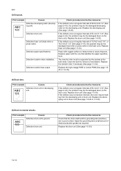
...or 1-5-39). Try adjusting the print density. If a developing unit which is known to conserve toner for check, replace the current developing unit in the drum unit) is available for draft printing purpose. Defective transfer bias output. The transfer roller must be set too high.... the EcoPrint mode off by the bushes at the both ends. For details, refer to the operation guide. Replace the drum unit (See page 1-5-30). Defective drum unit. Print example Causes Print density setting. Defective main charger grid. EcoPrint mode setting. ABC 123 Defective potential...
...or 1-5-39). Try adjusting the print density. If a developing unit which is known to conserve toner for check, replace the current developing unit in the drum unit) is available for draft printing purpose. Defective transfer bias output. The transfer roller must be set too high.... the EcoPrint mode off by the bushes at the both ends. For details, refer to the operation guide. Replace the drum unit (See page 1-5-30). Defective drum unit. Print example Causes Print density setting. Defective main charger grid. EcoPrint mode setting. ABC 123 Defective potential...

Service Manual
Page 134
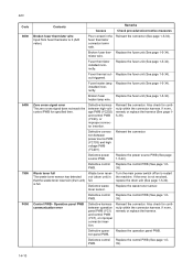
...is contaminated with toner, clean the transfer roller using a vacuum cleaner or by toner accumulated on the top edge or back of the drum and developing unit, and the fuser unit inlet. This vertical line should be caused by continuously printing a low density page until the symptom... has faded away. (10) Undulated printing at the right edge (scanning start position). Replace the control PWB (See page 1-5-39). 1-4-16 Check procedures/corrective measures Dirty edges and back of the paper can be straight. Print example ...
...is contaminated with toner, clean the transfer roller using a vacuum cleaner or by toner accumulated on the top edge or back of the drum and developing unit, and the fuser unit inlet. This vertical line should be caused by continuously printing a low density page until the symptom... has faded away. (10) Undulated printing at the right edge (scanning start position). Replace the control PWB (See page 1-5-39). 1-4-16 Check procedures/corrective measures Dirty edges and back of the paper can be straight. Print example ...

Service Manual
Page 138
.... lower registration rollers is extremely dirty or deformed. Check if the heat roller or press roller is correct. Check if the drum unit or developing unit is worn. Check visually and replace any deformed paper feed roller (assembly) (See page 1-56). Defective registration clutch installation. Paper width guide in the DP. ... paper is heard. (8)When the trouble occurs in a cassette installed incorrectly. Check if the paper feed roller is dirty with isopropyl alcohol. Clean the drum unit or developing unit (See page 1-5-30 or 1-5-29). Replace the fuser unit (See page 1-5-34...
.... lower registration rollers is extremely dirty or deformed. Check if the heat roller or press roller is correct. Check if the drum unit or developing unit is worn. Check visually and replace any deformed paper feed roller (assembly) (See page 1-56). Defective registration clutch installation. Paper width guide in the DP. ... paper is heard. (8)When the trouble occurs in a cassette installed incorrectly. Check if the paper feed roller is dirty with isopropyl alcohol. Clean the drum unit or developing unit (See page 1-5-30 or 1-5-29). Replace the fuser unit (See page 1-5-34...

Service Manual
Page 181
Open the front cover. 2. U251 Clearing the maintenance count (see page 1-3-30) 3. Check or replace the developing unit and refit all the removed parts. U111 Clearing the drum drive time (see page 1-3-36) 2. NOTE: When the periodic maintenance (replacing the maintenance kit, see page 1-3-31) 2JN-2 Developing unit Front cover Figure 1-5-44 1-5-29 Remove the developing unit. 3. U130 Initial setting for the developing unit (see page 2-4-4), perform following maintenance modes. 1. 1-5-5 Developing section (1) Detaching and refitting the developing unit Procedure 1.
Open the front cover. 2. U251 Clearing the maintenance count (see page 1-3-30) 3. Check or replace the developing unit and refit all the removed parts. U111 Clearing the drum drive time (see page 1-3-36) 2. NOTE: When the periodic maintenance (replacing the maintenance kit, see page 1-3-31) 2JN-2 Developing unit Front cover Figure 1-5-44 1-5-29 Remove the developing unit. 3. U130 Initial setting for the developing unit (see page 2-4-4), perform following maintenance modes. 1. 1-5-5 Developing section (1) Detaching and refitting the developing unit Procedure 1.

Service Manual
Page 182
U130 Initial setting for the developing unit (see page 1-3-36) 2. U251 Clearing the maintenance count (see page 1-3-31) Drum unit Figure 1-5-45 1-5-30 Remove the developing unit (See page 1-529). 2. Check or replace the drum unit and refit all the removed parts. U111 Clearing the drum drive time (see page 2-4-4), perform following maintenance modes. 1. NOTE: When the periodic maintenance (replacing the maintenance kit, see page 1-3-30) 3. 2JN-2 1-5-6 Drum section (1) Detaching and refitting the drum unit Procedure 1. Remove the drum unit. 3.
U130 Initial setting for the developing unit (see page 1-3-36) 2. U251 Clearing the maintenance count (see page 1-3-31) Drum unit Figure 1-5-45 1-5-30 Remove the developing unit (See page 1-529). 2. Check or replace the drum unit and refit all the removed parts. U111 Clearing the drum drive time (see page 2-4-4), perform following maintenance modes. 1. NOTE: When the periodic maintenance (replacing the maintenance kit, see page 1-3-30) 3. 2JN-2 1-5-6 Drum section (1) Detaching and refitting the drum unit Procedure 1. Remove the drum unit. 3.

Service Manual
Page 183
(2) Detaching and refitting the main charger unit Procedure 1. While pushing on the main plate ᕃ, slide the main charger unit ᕄ. 2JN Main charger unit Drum unit Main charger unit Main plate ᕃ ᕄ 5. Remove the main charger unit by lifting it. 6. Check or replace the main charger unit and refit all the removed parts. Remove the developing unit (See page 1-5- 29). 2. Remove the drum unit (See page 1-5-30). 3. Remove the tape. Figure 1-5-46 Main charger unit Figure 1-5-47 1-5-31 Tape 4.
(2) Detaching and refitting the main charger unit Procedure 1. While pushing on the main plate ᕃ, slide the main charger unit ᕄ. 2JN Main charger unit Drum unit Main charger unit Main plate ᕃ ᕄ 5. Remove the main charger unit by lifting it. 6. Check or replace the main charger unit and refit all the removed parts. Remove the developing unit (See page 1-5- 29). 2. Remove the drum unit (See page 1-5-30). 3. Remove the tape. Figure 1-5-46 Main charger unit Figure 1-5-47 1-5-31 Tape 4.


