
FS-1100/1300D Operation Guide Rev-1.2 (Basic)
Page 23
... are ready to remove and may be easily overlooked, deterring the paper jam recovery. WARNING If you ship the printer, remove and pack the develper unit and drum unit in a plastic bag and ship them separately from the carton until you are difficult to install it . Used ... Important Caution Warning Used to denote operation panel Printing resumes when [GO] is keys. Note Do not remove the toner container from the printer. Torn pieces of personal injury. IMPORTANT Take care not to provide important information. pressed. Used to touch the transfer roller (black) during...
... are ready to remove and may be easily overlooked, deterring the paper jam recovery. WARNING If you ship the printer, remove and pack the develper unit and drum unit in a plastic bag and ship them separately from the carton until you are difficult to install it . Used ... Important Caution Warning Used to denote operation panel Printing resumes when [GO] is keys. Note Do not remove the toner container from the printer. Torn pieces of personal injury. IMPORTANT Take care not to provide important information. pressed. Used to touch the transfer roller (black) during...
FS-1100/1300D Operation Guide Rev-1.2 (Basic)
Page 70
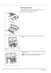
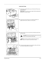
Cleaning the Printer To avoid print quality problems, the interior of the printer must be cleaned with every toner container replacement. 1 Open the top cover and front cover. 2 Lift the develper unit together with both hands. Never expose the drum unit to light. Developer Unit Drum Unit 3 Remove the drum unit from the printer by holding the green levers with the toner container out of the printer. Note The drum unit is sensitive to light for more than five minutes. 4-6 Maintenance
Cleaning the Printer To avoid print quality problems, the interior of the printer must be cleaned with every toner container replacement. 1 Open the top cover and front cover. 2 Lift the develper unit together with both hands. Never expose the drum unit to light. Developer Unit Drum Unit 3 Remove the drum unit from the printer by holding the green levers with the toner container out of the printer. Note The drum unit is sensitive to light for more than five minutes. 4-6 Maintenance

FS-1100/1300D Operation Guide Rev-1.2 (Basic)
Page 71
... make sure you restore the charger cleaner to its home position. 7 When cleaning is complete, return the drum unit to its original position (CLEANER HOME POSITION ). IMPORTANT Do not place the drum unit on the charger cleaner before cleaning for the first time. IMPORTANT Remove the fixing tape on end. 5... dust and dirt away from the metal registration roller. IMPORTANT Take care not to touch the transfer roller (black) during cleaning. 6 On the drum unit, slide the charger cleaner (green) back and forth 2 or 3 times to clean the charger wire, then return it to the original position....
... make sure you restore the charger cleaner to its home position. 7 When cleaning is complete, return the drum unit to its original position (CLEANER HOME POSITION ). IMPORTANT Do not place the drum unit on the charger cleaner before cleaning for the first time. IMPORTANT Remove the fixing tape on end. 5... dust and dirt away from the metal registration roller. IMPORTANT Take care not to touch the transfer roller (black) during cleaning. 6 On the drum unit, slide the charger cleaner (green) back and forth 2 or 3 times to clean the charger wire, then return it to the original position....
FS-1100/1300D Operation Guide Rev-1.2 (Basic)
Page 73
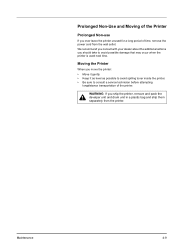
Maintenance 4-9 Prolonged Non-Use and Moving of the Printer Prolonged Non-use If you ever leave the printer unused for a long period of the printer. We recommend you consult with your dealer about the additional actions you should take to consult a service technician before attempting ... level as possible to avoid spilling toner inside the printer. • Be sure to avoid possible damage that may occur when the printer is used next time. Moving the Printer When you ship the printer, remove and pack the develper unit and drum unit in a plastic bag and ship them separately from...
Maintenance 4-9 Prolonged Non-Use and Moving of the Printer Prolonged Non-use If you ever leave the printer unused for a long period of the printer. We recommend you consult with your dealer about the additional actions you should take to consult a service technician before attempting ... level as possible to avoid spilling toner inside the printer. • Be sure to avoid possible damage that may occur when the printer is used next time. Moving the Printer When you ship the printer, remove and pack the develper unit and drum unit in a plastic bag and ship them separately from...
FS-1100/1300D Operation Guide Rev-1.2 (Basic)
Page 77
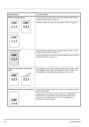
...the charger cleaner of the printer. Open the front cover and check that the toner container is not solved even after printing several pages, call for service. Dropouts, stray dots Drum or develper unit may require cleaning or replacing parts of the drum unit is in its original ...solve the problems. Some solutions may be damaged. Clean the charger wire. Refer to Cleaning the Printer on page 4-6. 5-3 If the problem is correctly installed in the printer. Vertical streaks Troubleshooting Check the toner container and if necessary replace. If the suggested corrective action ...
...the charger cleaner of the printer. Open the front cover and check that the toner container is not solved even after printing several pages, call for service. Dropouts, stray dots Drum or develper unit may require cleaning or replacing parts of the drum unit is in its original ...solve the problems. Some solutions may be damaged. Clean the charger wire. Refer to Cleaning the Printer on page 4-6. 5-3 If the problem is correctly installed in the printer. Vertical streaks Troubleshooting Check the toner container and if necessary replace. If the suggested corrective action ...
FS-1100/1300D Operation Guide Rev-1.2 (Basic)
Page 78
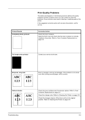
..., clean the registration roller. Gray background Check the toner container and if necessary replace. Refer to a command or command syntax. 5-4 Troubleshooting Check the develper unit and drum unit are correct in a parameter to Cleaning the Printer on page 4-2. Printed Results Faint or blurred printing Corrective Action Check the toner container and if necessary replace.
..., clean the registration roller. Gray background Check the toner container and if necessary replace. Refer to a command or command syntax. 5-4 Troubleshooting Check the develper unit and drum unit are correct in a parameter to Cleaning the Printer on page 4-2. Printed Results Faint or blurred printing Corrective Action Check the toner container and if necessary replace.
FS-1100/1300D Operation Guide Rev-1.2 (Basic)
Page 87
... has already been partially fed. IMPORTANT Do not try to be pinched by holding the green levers with the toner container out of the printer. 3 Remove the drum unit from the printer by rollers, pull it may result in burn injury. Do not touch it, as it along the normal running direction of the...
... has already been partially fed. IMPORTANT Do not try to be pinched by holding the green levers with the toner container out of the printer. 3 Remove the drum unit from the printer by rollers, pull it may result in burn injury. Do not touch it, as it along the normal running direction of the...
FS-1100/1300D Operation Guide Rev-1.2 (Basic)
Page 88
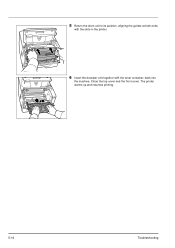
5 Return the drum unit to its position, aligning the guides at both ends with the slots in the printer. 6 Insert the develper unit together with the toner container, back into the machine. Close the top cover and the front cover. The printer warms up and resumes printing. 5-14 Troubleshooting
5 Return the drum unit to its position, aligning the guides at both ends with the slots in the printer. 6 Insert the develper unit together with the toner container, back into the machine. Close the top cover and the front cover. The printer warms up and resumes printing. 5-14 Troubleshooting

FS-1100/1300D Operation Guide Rev-1.2 (Basic)
Page 105
... section 5-15 Colored paper 2-9 CompactFlash card 6-2, 6-8 Components at the front of the printer 1-2 at the rear of the printer 1-3 Connection power cord 3-2 USB cable 3-2 Custom mode installation method 3-5 D Data indicator operation panel 1-4 Developer unit clearing paper jams 5-13 maintenance 4-6 DIMM 6-2 Drum unit clearing paper jams 5-13 maintenance 4-6 Duplexer clearing paper jams 5-12 E Energy Star program...
... section 5-15 Colored paper 2-9 CompactFlash card 6-2, 6-8 Components at the front of the printer 1-2 at the rear of the printer 1-3 Connection power cord 3-2 USB cable 3-2 Custom mode installation method 3-5 D Data indicator operation panel 1-4 Developer unit clearing paper jams 5-13 maintenance 4-6 DIMM 6-2 Drum unit clearing paper jams 5-13 maintenance 4-6 Duplexer clearing paper jams 5-12 E Energy Star program...
Service Manual
Page 11
...problems ...1-4-16 1-5 Assembly and Disassembly 1-5-1 Precautions for assembly and disassembly 1-5-1 (1) Precautions ...1-5-1 (2) Drum...1-5-1 (3) Toner container ...1-5-1 (4) How to tell a genuine Kyocera Mita toner container 1-5-2 1-5-2 Outer covers ...1-5-3 (1) Detaching and refitting the top cover 1-5-3 (2) ... Developing section...1-5-11 (1) Detaching and refitting the developing unit 1-5-11 1-5-5 Drum section...1-5-12 (1) Detaching and refitting the drum unit 1-5-12 (2) Detaching and refitting the main charger unit 1-5-13 1-5-6 Transfer/separation section ...1-5-14 (1) Detaching and...
...problems ...1-4-16 1-5 Assembly and Disassembly 1-5-1 Precautions for assembly and disassembly 1-5-1 (1) Precautions ...1-5-1 (2) Drum...1-5-1 (3) Toner container ...1-5-1 (4) How to tell a genuine Kyocera Mita toner container 1-5-2 1-5-2 Outer covers ...1-5-3 (1) Detaching and refitting the top cover 1-5-3 (2) ... Developing section...1-5-11 (1) Detaching and refitting the developing unit 1-5-11 1-5-5 Drum section...1-5-12 (1) Detaching and refitting the drum unit 1-5-12 (2) Detaching and refitting the main charger unit 1-5-13 1-5-6 Transfer/separation section ...1-5-14 (1) Detaching and...

Service Manual
Page 17
Paper feed/conveying section 4. Exit section 12. Developing unit 6. Transfer/separation section Light path Paper path Paper path (option) 10. Duplex/conveying section (Duplex model only) 1-1-5 Drum unit 8. Top tray 13. Toner container 13 9 1 3 Figure 1-1-3 5. MP tray 3. Cassette 2. Laser scanner unit 9. Main charger unit 7. 1-1-3 Machine cross section Simplex model 11 12 8 76 5 4 2H5/2HS 2 10 9 1 3 Duplex model 11 12 8 76 5 4 Light path Paper path Paper path (option) 2 10 1. Fuser section 11.
Paper feed/conveying section 4. Exit section 12. Developing unit 6. Transfer/separation section Light path Paper path Paper path (option) 10. Duplex/conveying section (Duplex model only) 1-1-5 Drum unit 8. Top tray 13. Toner container 13 9 1 3 Figure 1-1-3 5. MP tray 3. Cassette 2. Laser scanner unit 9. Main charger unit 7. 1-1-3 Machine cross section Simplex model 11 12 8 76 5 4 2H5/2HS 2 10 9 1 3 Duplex model 11 12 8 76 5 4 Light path Paper path Paper path (option) 2 10 1. Fuser section 11.
Service Manual
Page 46
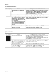
...PWB. Replace the laser scanner unit (See page 1-5-30). Print example Causes Check procedures/corrective measures Defective main charger unit. Replace the control PWB (See page 1-5-19). 1-4-10 Open the top cover and check that the drum unit and developing unit are correctly seated ...output. Investigate that the terminals between the main charger unit and the drum unit are not in loose contact. Defective control PWB. Print example Causes Check procedures/corrective measures Defective drum unit or developing unit. Replace the high voltage PWB (See page 1-5-25...
...PWB. Replace the laser scanner unit (See page 1-5-30). Print example Causes Check procedures/corrective measures Defective main charger unit. Replace the control PWB (See page 1-5-19). 1-4-10 Open the top cover and check that the drum unit and developing unit are correctly seated ...output. Investigate that the terminals between the main charger unit and the drum unit are not in loose contact. Defective control PWB. Print example Causes Check procedures/corrective measures Defective drum unit or developing unit. Replace the high voltage PWB (See page 1-5-25...
Service Manual
Page 47
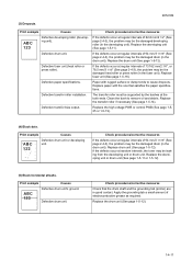
Defective transfer bias output. Paper with the one that the drum shaft and the grounding tab (printer) are in good contact. The transfer roller must be the damaged developing roller (in the drum unit). Replace the high voltage PWB or control PWB (See page 1-525 or 1-5-19). (4) Black dots. Apply the grounding tab a small amount...
Defective transfer bias output. Paper with the one that the drum shaft and the grounding tab (printer) are in good contact. The transfer roller must be the damaged developing roller (in the drum unit). Replace the high voltage PWB or control PWB (See page 1-525 or 1-5-19). (4) Black dots. Apply the grounding tab a small amount...

Service Manual
Page 48
... debris. The transfer roller must be set too high. If the symptom disappears, replace the developing unit with the one that the cleaning blade (in the printer with the normal one (See page 1-5-11). 1-4-12 Replace the drum unit (See page 1-5-12). Replace the high voltage PWB or control PWB (See page 1-525). Defective...
... debris. The transfer roller must be set too high. If the symptom disappears, replace the developing unit with the one that the cleaning blade (in the printer with the normal one (See page 1-5-11). 1-4-12 Replace the drum unit (See page 1-5-12). Replace the high voltage PWB or control PWB (See page 1-525). Defective...
Service Manual
Page 52
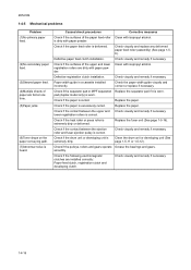
... (6)Toner drops on the paper conveying path. (7)Abnormal noise is heard. Defective registration clutch installation. Replace the paper. Check if the drum unit or developing unit is deformed. Clean the drum unit or developing unit (See page 1-5-11 or 1-5-12). Check if the following electromagnetic clutches are installed correctly: Paper feed clutch, registration clutch and developing...smoothly. is worn. Check if the contact between the upper and Check visually and remedy if necessary. lower registration rollers is correct. Replace the fuser unit (See page 1-5-16).
... (6)Toner drops on the paper conveying path. (7)Abnormal noise is heard. Defective registration clutch installation. Replace the paper. Check if the drum unit or developing unit is deformed. Clean the drum unit or developing unit (See page 1-5-11 or 1-5-12). Check if the following electromagnetic clutches are installed correctly: Paper feed clutch, registration clutch and developing...smoothly. is worn. Check if the contact between the upper and Check visually and remedy if necessary. lower registration rollers is correct. Replace the fuser unit (See page 1-5-16).

Service Manual
Page 53
... dark place. Avoid exposure to any object prone to turn the power switch off and disconnect the power plug before starting disassembly. Keep the drum at an ambient temperature between 0 °C/32 °F and 40 °C/104 °F and at a relative humidity not higher than .... (3) Toner container Store the toner container(s) in temperature and humidity. When removing the drum unit, never expose the drum surface to get the wire caught. (2) Drum Note the following when handling or storing the drum. Take care not to strong direct light. 2H5/2HS-1 1-5 Assembly and Disassembly 1-5-1 ...
... dark place. Avoid exposure to any object prone to turn the power switch off and disconnect the power plug before starting disassembly. Keep the drum at an ambient temperature between 0 °C/32 °F and 40 °C/104 °F and at a relative humidity not higher than .... (3) Toner container Store the toner container(s) in temperature and humidity. When removing the drum unit, never expose the drum surface to get the wire caught. (2) Drum Note the following when handling or storing the drum. Take care not to strong direct light. 2H5/2HS-1 1-5 Assembly and Disassembly 1-5-1 ...

Service Manual
Page 64
2H5/2HS 1-5-5 Drum section (1) Detaching and refitting the drum unit Procedure 1. Remove the drum unit. 3. Check or replace the drum unit and refit all the removed parts. Remove the developing unit (See page 1-511). 2. Drum unit Figure 1-5-16 1-5-12
2H5/2HS 1-5-5 Drum section (1) Detaching and refitting the drum unit Procedure 1. Remove the drum unit. 3. Check or replace the drum unit and refit all the removed parts. Remove the developing unit (See page 1-511). 2. Drum unit Figure 1-5-16 1-5-12

Service Manual
Page 65
While pushing on the main plate (ᕃ), slide the main charger unit (ᕄ). Remove the main charger unit by lifting it. 5. Check or replace the main charger unit and refit all the removed parts. Remove the drum unit (See page 1-5-12). 2. Tape 2H5/2HS-1 Main charger unit Drum unit Main charger unit Main plate ᕃ ᕄ 4. Remove the tape. 3. Figure 1-5-17 Main charger unit Figure 1-5-18 1-5-13 (2) Detaching and refitting the main charger unit Procedure 1.
While pushing on the main plate (ᕃ), slide the main charger unit (ᕄ). Remove the main charger unit by lifting it. 5. Check or replace the main charger unit and refit all the removed parts. Remove the drum unit (See page 1-5-12). 2. Tape 2H5/2HS-1 Main charger unit Drum unit Main charger unit Main plate ᕃ ᕄ 4. Remove the tape. 3. Figure 1-5-17 Main charger unit Figure 1-5-18 1-5-13 (2) Detaching and refitting the main charger unit Procedure 1.

Service Manual
Page 66
Remove the drum unit (See page 1-5-12). 3. Paper chute guide Paper chute guide Hook Hook Hook Hook Figure 1-5-19 1-5-14 2H5/2HS 1-5-6 Transfer/separation section (1) Detaching and refitting the transfer roller Procedure 1. Remove the paper chute guide. Remove the developing unit (See page 1-511). 2. Slide the paper chute guide and unhook the hooks. 4.
Remove the drum unit (See page 1-5-12). 3. Paper chute guide Paper chute guide Hook Hook Hook Hook Figure 1-5-19 1-5-14 2H5/2HS 1-5-6 Transfer/separation section (1) Detaching and refitting the transfer roller Procedure 1. Remove the paper chute guide. Remove the developing unit (See page 1-511). 2. Slide the paper chute guide and unhook the hooks. 4.

Service Manual
Page 77
... 12. Remove the drum unit (See page 1-5-12). 3. Remove the stop ring. 9. Remove the DU cover assembly. Remove the power source PWB (See page 1-5-22). 6. Figure 1-5-34 DU cover assembly DU bush Figure 1-5-35 1-5-25 Remove the developing unit (See page 1-511). 2. Remove the cassette (See page 1-5-6). 4. Turn the printer with the bottom side...
... 12. Remove the drum unit (See page 1-5-12). 3. Remove the stop ring. 9. Remove the DU cover assembly. Remove the power source PWB (See page 1-5-22). 6. Figure 1-5-34 DU cover assembly DU bush Figure 1-5-35 1-5-25 Remove the developing unit (See page 1-511). 2. Remove the cassette (See page 1-5-6). 4. Turn the printer with the bottom side...


