
User Guide
Page 1
Scanners Patch Code Information A-61599 CAT No. 845 9380 A-61599 October 2006
Scanners Patch Code Information A-61599 CAT No. 845 9380 A-61599 October 2006
User Guide
Page 2
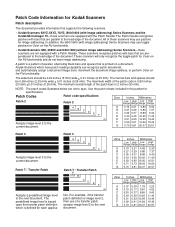
...pattern of the patch code is printed on a document. Use the patch sheets included in this packet for image addressing. Kodak Scanners which is based upon the transfer patch definition which have image addressing. The narrow bars and spaces should be 0.08 ...current document. Patch Code Information for Kodak Scanners Patch description This document provides information that supports the following scanners. • Kodak Scanners 9XYZ, 5XYZ, 7XYZ, i800/i1800 (with image addressing) Series Scanners and the Kodak Microimager 70-these scanners are not equipped with the Patch ...
...pattern of the patch code is printed on a document. Use the patch sheets included in this packet for image addressing. Kodak Scanners which is based upon the transfer patch definition which have image addressing. The narrow bars and spaces should be 0.08 ...current document. Patch Code Information for Kodak Scanners Patch description This document provides information that supports the following scanners. • Kodak Scanners 9XYZ, 5XYZ, 7XYZ, i800/i1800 (with image addressing) Series Scanners and the Kodak Microimager 70-these scanners are not equipped with the Patch ...
User Guide
Page 3
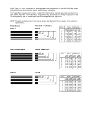
...scan image control for the i800/i1800 (with no need for specifications. This provides Color on the Fly during capture, with image addressing) Series Scanners (they are not to switch back and forth from bi-tonal and color/grayscale scanning for the i280, 3590C, i600, i800 and i1800 (...without image addressing) Series Scanners. Patch Types 1, 4 and 6 can be used for image addressing). NOTE: The patch codes illustrated below are not used to spec. The Toggle Patch...
...scan image control for the i800/i1800 (with no need for specifications. This provides Color on the Fly during capture, with image addressing) Series Scanners (they are not to switch back and forth from bi-tonal and color/grayscale scanning for the i280, 3590C, i600, i800 and i1800 (...without image addressing) Series Scanners. Patch Types 1, 4 and 6 can be used for image addressing). NOTE: The patch codes illustrated below are not used to spec. The Toggle Patch...
User Guide
Page 4
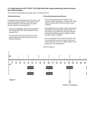
Make certain the side guides are five patch sensor locations for the scanner models listed above, except for proper operation. For Kodak Scanners 9XYZ, 5XYZ, 7XYZ, i800/i1800 (with the bars parallel to the leading edge of the document (fed into the transport first). • There ... vertical placement of Transport Refer to ensure the patch code may fail to sense the patch. • Patches should appear with image addressing) Series Scanners and 70 Microimager: The minimum overall length of the side guide(s). If the patch code is recommended to Figure A. Figure A Center of the ...
Make certain the side guides are five patch sensor locations for the scanner models listed above, except for proper operation. For Kodak Scanners 9XYZ, 5XYZ, 7XYZ, i800/i1800 (with the bars parallel to the leading edge of the document (fed into the transport first). • There ... vertical placement of Transport Refer to ensure the patch code may fail to sense the patch. • Patches should appear with image addressing) Series Scanners and 70 Microimager: The minimum overall length of the side guide(s). If the patch code is recommended to Figure A. Figure A Center of the ...

User Guide
Page 5
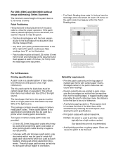
Refer to Figure B. A B Leading Edge of the document [1.6 inches (40 mm) on the 5XYZ and 7XYZ Scanners]. Vertical placement/positioning • Patch codes must appear at least 0.25 inches (6 mm) from the right, left, and leading edges of the document. • Patch ... Document (fed into transport first) C 3.75 inches (94 mm) Patch Area Figure B A, B, and C = 0.25 inches (6 mm) Patch Reader Positions for 9XYZ, 5XYZ, 7XYZ, i800 Series Scanners and 70 Microimager Patch Reader Positions for i1800 Series...
Refer to Figure B. A B Leading Edge of the document [1.6 inches (40 mm) on the 5XYZ and 7XYZ Scanners]. Vertical placement/positioning • Patch codes must appear at least 0.25 inches (6 mm) from the right, left, and leading edges of the document. • Patch ... Document (fed into transport first) C 3.75 inches (94 mm) Patch Area Figure B A, B, and C = 0.25 inches (6 mm) Patch Reader Positions for 9XYZ, 5XYZ, 7XYZ, i800 Series Scanners and 70 Microimager Patch Reader Positions for i1800 Series...
User Guide
Page 6
... spaces must reflect less than 20% of the light source. Soy-based inks are not fed into the transport without image addressing) Series Scanners The minimum overall length of the patch bars is used to print the black bars must be at least 0.5 inches (12.7 mm) ... (fed into the transport first). • Any other (non-patch) printed information to the left and right edge of the document. For All Scanners Printing specifications A patch code is critical for proper operation. Reliability requirements • Print the patch code only on application documents. • Full-page...
... spaces must reflect less than 20% of the light source. Soy-based inks are not fed into the transport without image addressing) Series Scanners The minimum overall length of the patch bars is used to print the black bars must be at least 0.5 inches (12.7 mm) ... (fed into the transport first). • Any other (non-patch) printed information to the left and right edge of the document. For All Scanners Printing specifications A patch code is critical for proper operation. Reliability requirements • Print the patch code only on application documents. • Full-page...


