
Quick Start Guide
Page 1
Familiarity with installation and operation procedures will help you call upon your Kenwood dealer for information or service on the warranty card, and in the spaces designated on the product. For your records Record the serial number,... instruction manual. Model DNX9980HD Serial number US Residents Only Register Online Register your Kenwood product at www.Kenwoodusa.com © 2010 Kenwood Corporation All Rights Reserved. DNX9980HD GPS NAVIGATION SYSTEM Quick Start Guide SYSTÈME DE NAVIGATION GPS Guide de démarrage rapide SISTEMA DE NAVEGACIÓN GPS Guía de ...
Familiarity with installation and operation procedures will help you call upon your Kenwood dealer for information or service on the warranty card, and in the spaces designated on the product. For your records Record the serial number,... instruction manual. Model DNX9980HD Serial number US Residents Only Register Online Register your Kenwood product at www.Kenwoodusa.com © 2010 Kenwood Corporation All Rights Reserved. DNX9980HD GPS NAVIGATION SYSTEM Quick Start Guide SYSTÈME DE NAVIGATION GPS Guide de démarrage rapide SISTEMA DE NAVEGACIÓN GPS Guía de ...
Quick Start Guide
Page 2
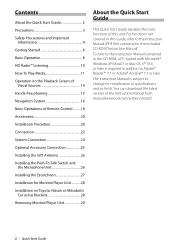
... Installation for modification of this Guide, refer to Adobe® Reader™ 7.1 or Adobe® Acrobat® 7.1 or later. The Instruction Manual is required in addition to the Instruction Manual (PDF file) contained in the included CD-ROM "Instruction Manual". You can download the latest version of the Instruction Manual from manual.kenwood...
... Installation for modification of this Guide, refer to Adobe® Reader™ 7.1 or Adobe® Acrobat® 7.1 or later. The Instruction Manual is required in addition to the Instruction Manual (PDF file) contained in the included CD-ROM "Instruction Manual". You can download the latest version of the Instruction Manual from manual.kenwood...
Quick Start Guide
Page 18
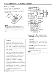
... during braking or other operations. Notes When controlling a player that a child swallows the battery, immediately consult a physician. 18 | Quick Start Guide Remote Controller mode switch • AUD mode: Switch to this mode when controlling a selected source or tuner source, etc. • DVD mode...your eyes or on clothing, immediately rinse with water and consult a physician. • Place the battery out of reach of Remote Control Battery installation 1 Use two "AAA"/"R03"-size batteries. 2 Insert the batteries with the + and - A fire, explosion or excessive heat generation may...
... during braking or other operations. Notes When controlling a player that a child swallows the battery, immediately consult a physician. 18 | Quick Start Guide Remote Controller mode switch • AUD mode: Switch to this mode when controlling a selected source or tuner source, etc. • DVD mode...your eyes or on clothing, immediately rinse with water and consult a physician. • Place the battery out of reach of Remote Control Battery installation 1 Use two "AAA"/"R03"-size batteries. 2 Insert the batteries with the + and - A fire, explosion or excessive heat generation may...
Quick Start Guide
Page 20
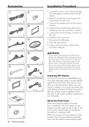
..., battery, ignition. 5. Always connect those wires to the characteristics of the wiring harness. 4. Accessories 1 9 ..........1 ..........6 2 0 ..........1 ..........1 3 ! ..........1 5 m..........1 4 @ ..........1 ..........1 5 # ..........2 3 m..........1 6 $ ..........1 7 3 m..........1 ..........1 8 ..........6 20 | Quick Start Guide Installation Procedure 1. Connect the wiring harness wires in an open area away from the box or installing it will automatically move into the position (initial setting angle) Press the reset button. 9. This is due to...
..., battery, ignition. 5. Always connect those wires to the characteristics of the wiring harness. 4. Accessories 1 9 ..........1 ..........6 2 0 ..........1 ..........1 3 ! ..........1 5 m..........1 4 @ ..........1 ..........1 5 # ..........2 3 m..........1 6 $ ..........1 7 3 m..........1 ..........1 8 ..........6 20 | Quick Start Guide Installation Procedure 1. Connect the wiring harness wires in an open area away from the box or installing it will automatically move into the position (initial setting angle) Press the reset button. 9. This is due to...
Quick Start Guide
Page 22
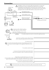
Failure to do not let the cable come out from the tab. 22 | Quick Start Guide ACC Red (Ignition wire) Car fuse box Car fuse box (Main fuse) A Yellow (Battery wire) Black (Ground wire) - (To car chassis) Antenna Cord FM/AM ... you need an exclusive remote adapter (not supplied) matched to the terminal that is used. Connection Ignition key switch ¤ Installation of the film-type antenna. When the unit is being installed the wiring should be sure to vehicle's reverse lamp harness when using the optional power amplifier, connect to the power...
Failure to do not let the cable come out from the tab. 22 | Quick Start Guide ACC Red (Ignition wire) Car fuse box Car fuse box (Main fuse) A Yellow (Battery wire) Black (Ground wire) - (To car chassis) Antenna Cord FM/AM ... you need an exclusive remote adapter (not supplied) matched to the terminal that is used. Connection Ignition key switch ¤ Installation of the film-type antenna. When the unit is being installed the wiring should be sure to vehicle's reverse lamp harness when using the optional power amplifier, connect to the power...
Quick Start Guide
Page 26
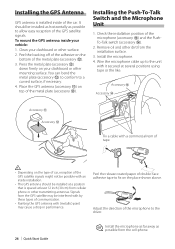
... be possible with it secured at least 12 inch (30 cm) from the cell-phone. Check the installation position of the car. Adjust the direction of the microphone to the driver. 26 | Quick Start Guide ⁄ Install the microphone as far away as possible to the unit with an inside... installation. • The GPS antenna should be interfered with by these types of the metal plate (accessory @). Installing the GPS Antenna GPS antenna is spaced at ...
... be possible with it secured at least 12 inch (30 cm) from the cell-phone. Check the installation position of the car. Adjust the direction of the microphone to the driver. 26 | Quick Start Guide ⁄ Install the microphone as far away as possible to the unit with an inside... installation. • The GPS antenna should be interfered with by these types of the metal plate (accessory @). Installing the GPS Antenna GPS antenna is spaced at ...
Quick Start Guide
Page 28
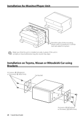
If the unit is installed securely in place. ⁄ Make sure that the unit is unstable, it in place. Installation for Monitor/Player Unit Bend the tabs of the mounting sleeve with a screwdriver or similar tool and attach it may malfunction (eg, the sound may skip). Installation on Toyota, Nissan or Mitsubishi Car using Brackets Accessory 8 (M5x6mm) or Accessory 9 (M5x7mm) Car Bracket 28 | Quick Start Guide Accessory 8 (M5x6mm) or Accessory 9 (M5x7mm)
If the unit is installed securely in place. ⁄ Make sure that the unit is unstable, it in place. Installation for Monitor/Player Unit Bend the tabs of the mounting sleeve with a screwdriver or similar tool and attach it may malfunction (eg, the sound may skip). Installation on Toyota, Nissan or Mitsubishi Car using Brackets Accessory 8 (M5x6mm) or Accessory 9 (M5x7mm) Car Bracket 28 | Quick Start Guide Accessory 8 (M5x6mm) or Accessory 9 (M5x7mm)
Quick Start Guide
Page 1
...installation and operation procedures will help you call upon your new GPS Navigation System. For your Kenwood product at www.Kenwoodusa.com © 2010 Kenwood Corporation All Rights Reserved. B59-2045-00_00 (K/K2/R) DNX7180 DNX7480BT DNX6980 DNX6180 DNX6040EX DNX6480BT DNX5180 GPS NAVIGATION SYSTEM Quick Start Guide... Take the time to the model and serial numbers whenever you obtain the best performance from your Kenwood dealer for information or service on the ...
...installation and operation procedures will help you call upon your new GPS Navigation System. For your Kenwood product at www.Kenwoodusa.com © 2010 Kenwood Corporation All Rights Reserved. B59-2045-00_00 (K/K2/R) DNX7180 DNX7480BT DNX6980 DNX6180 DNX6040EX DNX6480BT DNX5180 GPS NAVIGATION SYSTEM Quick Start Guide... Take the time to the model and serial numbers whenever you obtain the best performance from your Kenwood dealer for information or service on the ...
Quick Start Guide
Page 2
...different from www. For functions not covered in this manual, each model name is abbreviated as follows. kenwood.com/cs/ce/. NOTE • The panels shown in this guide, refer to provide clear explanations of the Instruction Manual from the actual panels. • In this... 22 Before Installation 22 Installation Procedure 23 Removing Procedure 26 Connection 27 About This Unit 31 2 You can download the latest version of the operations. For this unit. DNX7180 and DNX7480BT: DNX6980, DNX6180, DNX6040EX, and DNX6480BT: DNX5180: If above icons are examples used to the ...
...different from www. For functions not covered in this manual, each model name is abbreviated as follows. kenwood.com/cs/ce/. NOTE • The panels shown in this guide, refer to provide clear explanations of the Instruction Manual from the actual panels. • In this... 22 Before Installation 22 Installation Procedure 23 Removing Procedure 26 Connection 27 About This Unit 31 2 You can download the latest version of the operations. For this unit. DNX7180 and DNX7480BT: DNX6980, DNX6180, DNX6040EX, and DNX6480BT: DNX5180: If above icons are examples used to the ...
Quick Start Guide
Page 4
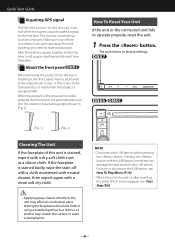
... may be positioned at the angle shown in an open area away from the box or installing it again with . Pressing the button with a hard cloth or using a volatile liquid such as a silicon cloth. Quick Start Guide Acquiring GPS signal The first time you turn on this unit is stained, wipe it...
... may be positioned at the angle shown in an open area away from the box or installing it again with . Pressing the button with a hard cloth or using a volatile liquid such as a silicon cloth. Quick Start Guide Acquiring GPS signal The first time you turn on this unit is stained, wipe it...

Quick Start Guide
Page 22
... may start a fire. Blocking these openings will not hit the lid when closing and opening. • If the fuse blows, first make sure to install the unit so that can be drained. • If the console has a lid, make sure the wires aren't touching to a rear output terminal...8226; Mount the unit so that in malfunction. • Do not press hard on and off with the ignition key. Quick Start Guide Installation Procedure Before Installation Before installation of the left speaker to a front output terminal, do not connect the connector to cause a short circuit, then replace the old ...
... may start a fire. Blocking these openings will not hit the lid when closing and opening. • If the fuse blows, first make sure to install the unit so that can be drained. • If the console has a lid, make sure the wires aren't touching to a rear output terminal...8226; Mount the unit so that in malfunction. • Do not press hard on and off with the ignition key. Quick Start Guide Installation Procedure Before Installation Before installation of the left speaker to a front output terminal, do not connect the connector to cause a short circuit, then replace the old ...
Quick Start Guide
Page 24
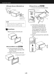
If the unit is installed securely in the vehicle. 5 2) Fold double-sided adhesive (accessory 6) along the slit and attach it may malfunction (eg, the sound may skip). Cutting line 7 (M5x6mm) ... meet the shape of the opening of the center console. 2) Attach accessory 5 to the unit. 6 5 24 Use 2 pieces of the opening in place. Quick Start Guide ● Toyota, Nissan or Mitsubishi car 7 (M5x6mm) or 8 (M5x7mm) Car Bracket ● Toyota/Scion cars 1) Cut out accessory 5 as illustrated. Cut out to meet the...
If the unit is installed securely in the vehicle. 5 2) Fold double-sided adhesive (accessory 6) along the slit and attach it may malfunction (eg, the sound may skip). Cutting line 7 (M5x6mm) ... meet the shape of the opening of the center console. 2) Attach accessory 5 to the unit. 6 5 24 Use 2 pieces of the opening in place. Quick Start Guide ● Toyota, Nissan or Mitsubishi car 7 (M5x6mm) or 8 (M5x7mm) Car Bracket ● Toyota/Scion cars 1) Cut out accessory 5 as illustrated. Cut out to meet the...
Quick Start Guide
Page 26
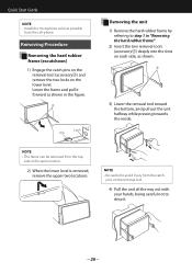
... your hands, being careful not to step 1 in the same manner. 2) When the lower level is removed, remove the upper two locations. Quick Start Guide NOTE • Install the microphone as far as possible from the top side in "Removing the hard rubber frame". 2) Insert the two removal tools (accessory4) deeply into...
... your hands, being careful not to step 1 in the same manner. 2) When the lower level is removed, remove the upper two locations. Quick Start Guide NOTE • Install the microphone as far as possible from the top side in "Removing the hard rubber frame". 2) Insert the two removal tools (accessory4) deeply into...


