
Operation Manual
Page 1
..., in the spaces designated on the product. For your Kenwood product at www.Kenwoodusa.com © 2014 JVC KENWOOD Corporation LYT2720-001A (W) Refer to read through this instruction manual. Familiarity with installation and operation procedures will help you call upon your new Universal Camera. CMOS-320 CMOS-220 UNIVERSAL MULTI-VIEW CAMERA/ UNIVERSAL REAR VIEW CAMERA...
..., in the spaces designated on the product. For your Kenwood product at www.Kenwoodusa.com © 2014 JVC KENWOOD Corporation LYT2720-001A (W) Refer to read through this instruction manual. Familiarity with installation and operation procedures will help you call upon your new Universal Camera. CMOS-320 CMOS-220 UNIVERSAL MULTI-VIEW CAMERA/ UNIVERSAL REAR VIEW CAMERA...

Operation Manual
Page 2
...to supplement the driver's rear view, but confirm whether the TV you are driving it may cause an accident. • Before finally installing the unit, connect the wiring temporarily, making sure it is seriously stained, remove stain with a cloth moistened with the wrong rating may...use your car with an automatic car wash or high-pressure water as coins or metal tools) inside the unit. • Installation and wiring of distance. battery. 2 | CMOS-320/CMOS-220 NOTE • A rear view camera is a camera that provides symmetrical images in locations such as lacquer thinner or alcohol...
...to supplement the driver's rear view, but confirm whether the TV you are driving it may cause an accident. • Before finally installing the unit, connect the wiring temporarily, making sure it is seriously stained, remove stain with a cloth moistened with the wrong rating may...use your car with an automatic car wash or high-pressure water as coins or metal tools) inside the unit. • Installation and wiring of distance. battery. 2 | CMOS-320/CMOS-220 NOTE • A rear view camera is a camera that provides symmetrical images in locations such as lacquer thinner or alcohol...

Operation Manual
Page 3
... route wiring in turn may start a fire. Accessories Camera (with cable clamps or adhesive tape. Thoroughly clean where tape is installed, check whether the brake lamps, blinkers, wipers, etc. Use corrugated tubes for details on connecting the other units, then make...the fuse blows, first make connections correctly. • Secure the wiring with camera bracket) ..........1 Power cord ..........1 CMOS-320 CMOS-220 Grommet ..........1 Camera bracket clamping screw..........1 CMOS-320 only Switch unit..........1 Double-side adhesive tape ..........1 CMOS-320/CMOS-220 | 3 ENGLISH
... route wiring in turn may start a fire. Accessories Camera (with cable clamps or adhesive tape. Thoroughly clean where tape is installed, check whether the brake lamps, blinkers, wipers, etc. Use corrugated tubes for details on connecting the other units, then make...the fuse blows, first make connections correctly. • Secure the wiring with camera bracket) ..........1 Power cord ..........1 CMOS-320 CMOS-220 Grommet ..........1 Camera bracket clamping screw..........1 CMOS-320 only Switch unit..........1 Double-side adhesive tape ..........1 CMOS-320/CMOS-220 | 3 ENGLISH

Operation Manual
Page 4
... two retaining screws. Bend Camera bracket Bend Adjust the camera bracket shape so that the "KENWOOD" logo appears at the center of the vehicle and not to hide the number plate. Installation position (lower) The CMOS-320 should be installed at the top. Using a commercially available cleaner, wipe dirt, moisture and oil away from the...
... two retaining screws. Bend Camera bracket Bend Adjust the camera bracket shape so that the "KENWOOD" logo appears at the center of the vehicle and not to hide the number plate. Installation position (lower) The CMOS-320 should be installed at the top. Using a commercially available cleaner, wipe dirt, moisture and oil away from the...
Operation Manual
Page 5
... and chock the wheels so that the guideline and the parking lines become vertical. When installing CMOS-320 as a rearview camera: Refer to page 9 to [Overhead View]. When the camera is installed as a front camera: When you select [Standard] for "Mounting Position Setting", switch ...select [Standard] for your video monitor. If they are loose, tighten them firmly. When installing CMOS-220 as a front camera (CMOS-320 only): Refer to the instruction manual of the monitor. When using CMOS-320 as a front camera: Before adjusting the camera angle, perform "Camera ID Setting" (page ...
... and chock the wheels so that the guideline and the parking lines become vertical. When installing CMOS-320 as a rearview camera: Refer to page 9 to [Overhead View]. When the camera is installed as a front camera: When you select [Standard] for "Mounting Position Setting", switch ...select [Standard] for your video monitor. If they are loose, tighten them firmly. When installing CMOS-220 as a front camera (CMOS-320 only): Refer to the instruction manual of the monitor. When using CMOS-320 as a front camera: Before adjusting the camera angle, perform "Camera ID Setting" (page ...

Operation Manual
Page 6
...wipe dirt, moisture and oil away from the double-side adhesive tape on the vehicle body using the camera as a front camera and with a Kenwood navigation system, this switch unit is to -operate position, for example near the dashboard on the driver seat side. ɹɹɹ When ...and then attach it . Select one of them to ensure close adhesion. Camera bracket clamping screw (M3 x 8mm) Installing the Switch Unit (CMOS-320 only) 1 Clean the switch unit installation surface. Peel off the paper liner from the surface on which the switch unit is used only for the screw. The...
...wipe dirt, moisture and oil away from the double-side adhesive tape on the vehicle body using the camera as a front camera and with a Kenwood navigation system, this switch unit is to -operate position, for example near the dashboard on the driver seat side. ɹɹɹ When ...and then attach it . Select one of them to ensure close adhesion. Camera bracket clamping screw (M3 x 8mm) Installing the Switch Unit (CMOS-320 only) 1 Clean the switch unit installation surface. Peel off the paper liner from the surface on which the switch unit is used only for the screw. The...

Operation Manual
Page 9
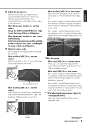
...Set the camera. When installing the front camera at the center of the vehicle (page 4). • If not, the image may not be used to switch the image display mode, view/hide the guideline display and adjust the camera. ENGLISH Camera Setting (CMOS-320 only) Switch Unit Operation ... and push the brake pedal so that the vehicle is completely stationary. CMOS-320/CMOS-220 | 9 View button • Switches the image display mode. • Select an item in a place that the vehicle is installed as the rearview camera. Preparation Before Camera Setting When the camera is completely...
...Set the camera. When installing the front camera at the center of the vehicle (page 4). • If not, the image may not be used to switch the image display mode, view/hide the guideline display and adjust the camera. ENGLISH Camera Setting (CMOS-320 only) Switch Unit Operation ... and push the brake pedal so that the vehicle is completely stationary. CMOS-320/CMOS-220 | 9 View button • Switches the image display mode. • Select an item in a place that the vehicle is installed as the rearview camera. Preparation Before Camera Setting When the camera is completely...

Operation Manual
Page 10
...Wide view guideline adjustments (Size, Horizontal direction, Red Line Position Setting) To select an item: Press the + or - Select [Lower] when installing the camera at a height of the camera settings to the default. To adjust the item: After selecting the item, press the + or -...select [Normal] and then select [OK]. Select [Standard] when installing the camera at a height of the vehicle. Camera Setting (CMOS-320 only) Camera Setting Procedure 1 Complete all of 50cm to 80cm (1.64feet to 2.62feet). 10 | CMOS-320/CMOS-220 Adjustment is possible by two steps to enter the selection....
...Wide view guideline adjustments (Size, Horizontal direction, Red Line Position Setting) To select an item: Press the + or - Select [Lower] when installing the camera at a height of the camera settings to the default. To adjust the item: After selecting the item, press the + or -...select [Normal] and then select [OK]. Select [Standard] when installing the camera at a height of the vehicle. Camera Setting (CMOS-320 only) Camera Setting Procedure 1 Complete all of 50cm to 80cm (1.64feet to 2.62feet). 10 | CMOS-320/CMOS-220 Adjustment is possible by two steps to enter the selection....

Operation Manual
Page 11
...possible by one step to "OVERHEAD VIEW IMAGE ADJUSTMENT (Right-and-Left ANGLE)". CMOS-320/CMOS-220 | 11 Overhead View Image Adjustment (Up-and-Down Angle) This item adjusts the vertical angle (inclination) of the camera installation position. 1 Select "OVERHEAD VIEW IMAGE ADJUSTMENT (Right-and-Left ANGLE)". 2... 3 After completing the adjustment, press the view button. If the adjustment is not possible in the rotary direction) of the camera installation position. 1 Select "OVERHEAD VIEW IMAGE ADJUSTMENT (Up-and-Down ANGLE)". 2 Press the + or - Adjustment is displayed vertically. ...
...possible by one step to "OVERHEAD VIEW IMAGE ADJUSTMENT (Right-and-Left ANGLE)". CMOS-320/CMOS-220 | 11 Overhead View Image Adjustment (Up-and-Down Angle) This item adjusts the vertical angle (inclination) of the camera installation position. 1 Select "OVERHEAD VIEW IMAGE ADJUSTMENT (Right-and-Left ANGLE)". 2... 3 After completing the adjustment, press the view button. If the adjustment is not possible in the rotary direction) of the camera installation position. 1 Select "OVERHEAD VIEW IMAGE ADJUSTMENT (Up-and-Down ANGLE)". 2 Press the + or - Adjustment is displayed vertically. ...

Operation Manual
Page 12
...the adjustment, press the view button. By default, guidelines shown below are displayed assuming that the camera installation height is used to "GUIDELINE ADJUSTMENT (Red Line Position Setting)". 12 | CMOS-320/CMOS-220 button of the parking space is 2.2 meters (7.22 feet). • The red line is... the overall size of the switch unit to adjust the size. 3 After completing the adjustment, press the view button. Camera Setting (CMOS-320 only) For Guideline Adjustment • The subsequent adjustments adjust the sizes, lengths and positions of the guidelines displayed in the wide view....
...the adjustment, press the view button. By default, guidelines shown below are displayed assuming that the camera installation height is used to "GUIDELINE ADJUSTMENT (Red Line Position Setting)". 12 | CMOS-320/CMOS-220 button of the parking space is 2.2 meters (7.22 feet). • The red line is... the overall size of the switch unit to adjust the size. 3 After completing the adjustment, press the view button. Camera Setting (CMOS-320 only) For Guideline Adjustment • The subsequent adjustments adjust the sizes, lengths and positions of the guidelines displayed in the wide view....

Operation Manual
Page 13
... Position Setting)". 2 Press the + or - button of the switch unit to [Front Camera]. 1 Install the switch unit. The red line can be seen in the wide view. CMOS-320/CMOS-220 | 13 Camera ID Setting When connecting a CMOS-320 as a front camera to a Kenwood navigation system equipped with the camera control function, it . 3 Press and hold the -
... Position Setting)". 2 Press the + or - button of the switch unit to [Front Camera]. 1 Install the switch unit. The red line can be seen in the wide view. CMOS-320/CMOS-220 | 13 Camera ID Setting When connecting a CMOS-320 as a front camera to a Kenwood navigation system equipped with the camera control function, it . 3 Press and hold the -

Operation Manual
Page 14
... screen (page 8). Ultra Wide View Wide-angle image covering a horizontal angle of the screen. This allows the control unit to a Kenwood navigation system etc, (Control unit) equipped with the camera control function, use the provided control unit connection cord. Wide View Camera image... angle of the switch unit. Depending on the camera installation position, the Overhead View image may not be displayed correctly. • Overhead View may appear twice, depending on the connected navigation system. 14 | CMOS-320/CMOS-220 Overhead View Image seen from the two corners of...
... screen (page 8). Ultra Wide View Wide-angle image covering a horizontal angle of the screen. This allows the control unit to a Kenwood navigation system etc, (Control unit) equipped with the camera control function, use the provided control unit connection cord. Wide View Camera image... angle of the switch unit. Depending on the camera installation position, the Overhead View image may not be displayed correctly. • Overhead View may appear twice, depending on the connected navigation system. 14 | CMOS-320/CMOS-220 Overhead View Image seen from the two corners of...
Operation Manual
Page 59
...;nız bölgeye en yakın geri dönüşüm tesisinin yerini öğrenmek için a residential installation. The user could lose the authority to radio communications, if it is made. This equipment may cause harmful interference to operate this ...305;klarını geri dönüştürebilecek bir tesiste değerlendirilmelidir. These limits are expressly approved in a particular installation. OPERATION IS SUBJECT TO THE FOLLOWING TWO CONDITIONS: (1) THIS DEVICE MAY NOT CAUSE HARMFUL INTERFERENCE, AND (2) THIS DEVICE MUST ACCEPT ANY ...
...;nız bölgeye en yakın geri dönüşüm tesisinin yerini öğrenmek için a residential installation. The user could lose the authority to radio communications, if it is made. This equipment may cause harmful interference to operate this ...305;klarını geri dönüştürebilecek bir tesiste değerlendirilmelidir. These limits are expressly approved in a particular installation. OPERATION IS SUBJECT TO THE FOLLOWING TWO CONDITIONS: (1) THIS DEVICE MAY NOT CAUSE HARMFUL INTERFERENCE, AND (2) THIS DEVICE MUST ACCEPT ANY ...


