Instructions
Page 3
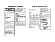
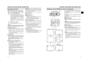
...the equipment off and appropriate one or more of the following length: Camera Port DC INPUT INPUT1/2 LINE OUTPUT PHONES 1/2 VIDEO/Y, PB, PR IEEE1394 (HDV/DV) Cable Exclusive Cable Shielded Cable Shielded Cable Shielded Cable Shielded Cable Exclusive Cable Length 2 m 3 m 1.5 m 2 m 3 m 4.5 m AC ...radio frequency energy and, if not installed and used in the literature accompanying the appliance. CAUTION: CHANGES OR MODIFICATIONS NOT APPROVED BY JVC COULD VOID USER'S AUTHORITY TO OPERATE THE EQUIPMENT. ATTENTION : Afin d'eviter tout resque d'incendie ou d'électrocution, ne pas...
...the equipment off and appropriate one or more of the following length: Camera Port DC INPUT INPUT1/2 LINE OUTPUT PHONES 1/2 VIDEO/Y, PB, PR IEEE1394 (HDV/DV) Cable Exclusive Cable Shielded Cable Shielded Cable Shielded Cable Shielded Cable Exclusive Cable Length 2 m 3 m 1.5 m 2 m 3 m 4.5 m AC ...radio frequency energy and, if not installed and used in the literature accompanying the appliance. CAUTION: CHANGES OR MODIFICATIONS NOT APPROVED BY JVC COULD VOID USER'S AUTHORITY TO OPERATE THE EQUIPMENT. ATTENTION : Afin d'eviter tout resque d'incendie ou d'électrocution, ne pas...
Instructions
Page 4
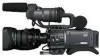
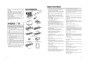
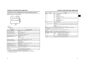
... filter operations, the FAS function automatically provides a wide range of tapes, we recommend not to record pictures within HDV for purchasing the JVC GY-HD110U/CHU, GYHD110E/CHE and GY-HD111E/CHE HD CAMERA RECORDER. finder Cable (Black) Clamp Filters For Audio/IEEE1394 Cable Audio... effective scan lines, progressive scan) HDV 1080i (1080 effective scan lines, interlaced scan) This camcorder supports HDV 720p format. (HDV 720p, 480p, 576p) HDV and are recorded or played back on Mini DV videocas- The speaker also outputs an alarm tone in case an abnormal condition occurs in the ...
... filter operations, the FAS function automatically provides a wide range of tapes, we recommend not to record pictures within HDV for purchasing the JVC GY-HD110U/CHU, GYHD110E/CHE and GY-HD111E/CHE HD CAMERA RECORDER. finder Cable (Black) Clamp Filters For Audio/IEEE1394 Cable Audio... effective scan lines, progressive scan) HDV 1080i (1080 effective scan lines, interlaced scan) This camcorder supports HDV 720p format. (HDV 720p, 480p, 576p) HDV and are recorded or played back on Mini DV videocas- The speaker also outputs an alarm tone in case an abnormal condition occurs in the ...
Instructions
Page 5
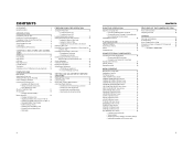
...of Time Code 40 • Presetting time code data • Presetting user's bit data Synchronizing with the Time Code of the IEEE1394 (DV)-Connected Master Unit 42 Screen Adjustment 43 Viewfinder Adjustment 43 Back Focus Adjustment 44 White Balance Adjustment 45 • White Balance Adjustment •... the Video Signal Cables 56 • Connecting the IEEE1394 Cable • Composite and Component Connections Dubbing with AV Devices 57 HDV/DV Dubbing 58 Backup Recording 60 MENU SCREENS Menu Screen Configuration 61 Setting Menu Screens 62 TOP MENU Screen 63 VIDEO FORMAT Menu Screen...
...of Time Code 40 • Presetting time code data • Presetting user's bit data Synchronizing with the Time Code of the IEEE1394 (DV)-Connected Master Unit 42 Screen Adjustment 43 Viewfinder Adjustment 43 Back Focus Adjustment 44 White Balance Adjustment 45 • White Balance Adjustment •... the Video Signal Cables 56 • Connecting the IEEE1394 Cable • Composite and Component Connections Dubbing with AV Devices 57 HDV/DV Dubbing 58 Backup Recording 60 MENU SCREENS Menu Screen Configuration 61 Setting Menu Screens 62 TOP MENU Screen 63 VIDEO FORMAT Menu Screen...
Instructions
Page 7
... store them lying flat. In such a case, it . 8 9 Do not continue to use M-DV80. • Videocassettes cannot be Used • Use JVC's videocassette tapes marked with the A symbol. • Mini DV videocassette : M-DV63HD M-DV63PROHD * Do not use a dirty or damaged tape, as this will reduce the rotary head life. • Videocassette tapes...
... store them lying flat. In such a case, it . 8 9 Do not continue to use M-DV80. • Videocassettes cannot be Used • Use JVC's videocassette tapes marked with the A symbol. • Mini DV videocassette : M-DV63HD M-DV63PROHD * Do not use a dirty or damaged tape, as this will reduce the rotary head life. • Videocassette tapes...
Instructions
Page 9
... in the CH-1/CH-2 AUDIO LEVEL area g on page 15 lights. : Allows you to prevent the camera from the IEEE1394 connector 4 on page 16. (HDV/DV signal input is possible with the ALARM VR LEVEL item on the OTHERS [1/2] menu screen. • When using the CH-1/CH-2 AUDIO LEVEL volume controls... power is turned on, the mode becomes the Camera mode. 13 It is also used for setting the time code generator to input the HDV/DV signal from falling off the tripod. The audio channel to the standard setting. 2[CH-1/CH-2 AUDIO SELECT] CH-1/CH-2 audio selector switch Selects the method...
... in the CH-1/CH-2 AUDIO LEVEL area g on page 15 lights. : Allows you to prevent the camera from the IEEE1394 connector 4 on page 16. (HDV/DV signal input is possible with the ALARM VR LEVEL item on the OTHERS [1/2] menu screen. • When using the CH-1/CH-2 AUDIO LEVEL volume controls... power is turned on, the mode becomes the Camera mode. 13 It is also used for setting the time code generator to input the HDV/DV signal from falling off the tripod. The audio channel to the standard setting. 2[CH-1/CH-2 AUDIO SELECT] CH-1/CH-2 audio selector switch Selects the method...
Instructions
Page 10
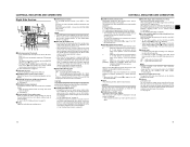
... The sound level is displayed in B. B : Switch into A. item on page 60. X See page 66. CAUTION There is a risk that the camcorder will be viewed when this is opened. f[REC] REC trigger button (start /stop recording using this dial. X See "Backup Recording" on the CAMERA OPERATION... OTHERS [2/2] menu screen, this button becomes the start /stop recording) Start and stop recording button for an external device. X See page 81. DV : Lights when the format is HDV. X See page 43. 5[PEAKING] Contour adjustment To adjust the contours of the item, press this button....
... The sound level is displayed in B. B : Switch into A. item on page 60. X See page 66. CAUTION There is a risk that the camcorder will be viewed when this is opened. f[REC] REC trigger button (start /stop recording using this dial. X See "Backup Recording" on the CAMERA OPERATION... OTHERS [2/2] menu screen, this button becomes the start /stop recording) Start and stop recording button for an external device. X See page 81. DV : Lights when the format is HDV. X See page 43. 5[PEAKING] Contour adjustment To adjust the contours of the item, press this button....
Instructions
Page 11
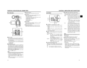
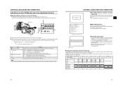
...34 5 6 7 8 9 1 b a 0 1[DC INPUT] DC connector Power input for component or composite video signal output. HDV : For HDV format DV : DV format 4[IEEE1394] IEEE1394 connector (6-pin) Using an IEEE1394 cable (optional), a digital video component with AV Devices" on the right panel and the lens VTR trigger...connector selector switch Selects the CH-2 audio input connector. MEMO You can adjust the position of the videocassette. When you press this camcorder. • You can adjust the position of the shoulder pad. Do not close the cassette cover during the eject operation. •...
...34 5 6 7 8 9 1 b a 0 1[DC INPUT] DC connector Power input for component or composite video signal output. HDV : For HDV format DV : DV format 4[IEEE1394] IEEE1394 connector (6-pin) Using an IEEE1394 cable (optional), a digital video component with AV Devices" on the right panel and the lens VTR trigger...connector selector switch Selects the CH-2 audio input connector. MEMO You can adjust the position of the videocassette. When you press this camcorder. • You can adjust the position of the shoulder pad. Do not close the cassette cover during the eject operation. •...
Instructions
Page 12
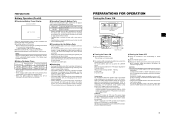
...) MEMO When the OUTPUT CHAR. X See "Magnified Status Indications on the LCD Monitor" on page 55. To perform VTR playback or to input the HDV/DV signal from the monitoring speaker. CAUTION When the power is turned on the LCD Monitor and in the VTR mode. j[REW] Rewind button Press this... adjustment mode or manual adjustment mode for 1 second or longer, the menu setting screen is output. It flashes when the mode is being changed. (HDV/DV signal input is possible with the GY-HD110U, GYHD111E.) h[FULL AUTO] Full auto shooting (FAS) switch This is the ON/OFF switch for checking the...
...) MEMO When the OUTPUT CHAR. X See "Magnified Status Indications on the LCD Monitor" on page 55. To perform VTR playback or to input the HDV/DV signal from the monitoring speaker. CAUTION When the power is turned on the LCD Monitor and in the VTR mode. j[REW] Rewind button Press this... adjustment mode or manual adjustment mode for 1 second or longer, the menu setting screen is output. It flashes when the mode is being changed. (HDV/DV signal input is possible with the GY-HD110U, GYHD111E.) h[FULL AUTO] Full auto shooting (FAS) switch This is the ON/OFF switch for checking the...
Instructions
Page 13
..., 1/48, 1/50, 1/60, 1/100, 1/120, 1/250, 1/500, 1/1000, 1/2000,1/4000, 1/10000 Variable shutter speed value was sent from the IEEE1394 TRIGGER TO HDV, TRIGGER TO DV connector Other Displays X See "FILE MANAGE Menu Screen" on page 83-85. SHUTTER 1/24.01 to zero reset REC LOCK switch was changed *2 BLACK NORMAL...
..., 1/48, 1/50, 1/60, 1/100, 1/120, 1/250, 1/500, 1/1000, 1/2000,1/4000, 1/10000 Variable shutter speed value was sent from the IEEE1394 TRIGGER TO HDV, TRIGGER TO DV connector Other Displays X See "FILE MANAGE Menu Screen" on page 83-85. SHUTTER 1/24.01 to zero reset REC LOCK switch was changed *2 BLACK NORMAL...

Instructions
Page 15
...non-linear editing software.) (SLOW+1: About ×0.1 speed, SLOW+2: About ×0.2 speed, SLOW+3: About ×0.5 speed) During variable playback in DV format, the data from LOAD FILE was changed. Events are not displayed while these statuses are set , the following indication appears. 9 Voltage indication... this screen is set with the AUDIO item on the LCD Monitor and in 0.1V steps. 0 Audio Lock indication Displayed when the audio signal from DV recording or playback is displayed during playback. A, B, PRESET, FAW For A and B, ## represents 23, 25, 28, 30, 32, 34, 37...
...non-linear editing software.) (SLOW+1: About ×0.1 speed, SLOW+2: About ×0.2 speed, SLOW+3: About ×0.5 speed) During variable playback in DV format, the data from LOAD FILE was changed. Events are not displayed while these statuses are set , the following indication appears. 9 Voltage indication... this screen is set with the AUDIO item on the LCD Monitor and in 0.1V steps. 0 Audio Lock indication Displayed when the audio signal from DV recording or playback is displayed during playback. A, B, PRESET, FAW For A and B, ## represents 23, 25, 28, 30, 32, 34, 37...
Instructions
Page 16
... displayed No. The Menu Setting Screen appears when the STATUS button is set to display the alarm. SAFETY ZONE CENTER MARK REC ASPECT DV-60I DV-24P 4:3 DV-24PA DV-50I DV-25P 16:9 HDV-SD60P HDV-SD50P HDV-HD30P HDV-HD25P HDV-HD24P [16:9] OFF - 4:3 OFF ON 14:9 OFF ON 16:9 OFF ON 16...
... displayed No. The Menu Setting Screen appears when the STATUS button is set to display the alarm. SAFETY ZONE CENTER MARK REC ASPECT DV-60I DV-24P 4:3 DV-24PA DV-50I DV-25P 16:9 HDV-SD60P HDV-SD50P HDV-HD30P HDV-HD25P HDV-HD24P [16:9] OFF - 4:3 OFF ON 14:9 OFF ON 16:9 OFF ON 16...

Instructions
Page 17
... CASE TRIPOD BASE KA-551 TRIPOD IEEE1394 CABLE 6P-6P Battery Battery Charger IDX Anton Bauer HDD UNIT DR-HD100 DV VTR BR-HD50 Non-linear Editing SYSTEM DOLLY *1 An HZ-FM13 cannot be used with the screen in the... to ON, the LCD monitor and viewfinder (VF) displays are as shown below . For details, please consult your JVC authorized dealer. 28 29 UB RFRECEE REGEN LCD open /close less than 40° When using these batteries and the... normal/inverted operations. • If the LCD monitor is closed inside the camcorder with a Th16×5.5BRMU or S14×7.3B12/U zoom lens.
... CASE TRIPOD BASE KA-551 TRIPOD IEEE1394 CABLE 6P-6P Battery Battery Charger IDX Anton Bauer HDD UNIT DR-HD100 DV VTR BR-HD50 Non-linear Editing SYSTEM DOLLY *1 An HZ-FM13 cannot be used with the screen in the... to ON, the LCD monitor and viewfinder (VF) displays are as shown below . For details, please consult your JVC authorized dealer. 28 29 UB RFRECEE REGEN LCD open /close less than 40° When using these batteries and the... normal/inverted operations. • If the LCD monitor is closed inside the camcorder with a Th16×5.5BRMU or S14×7.3B12/U zoom lens.
Instructions
Page 20
... or on the LCD monitor. When a recordable videocassette is possible through the IEEE1394 connector. (GY-HD110U/GY-HD111E only) „ Turning the Power OFF 1. HDV/DV input is loaded, the GY-HD110 enters the record-standby mode automatically. Remove the battery pack or the power supply to the DC INPUT connector...
... or on the LCD monitor. When a recordable videocassette is possible through the IEEE1394 connector. (GY-HD110U/GY-HD111E only) „ Turning the Power OFF 1. HDV/DV input is loaded, the GY-HD110 enters the record-standby mode automatically. Remove the battery pack or the power supply to the DC INPUT connector...
Instructions
Page 22
...Camera mode : The date and time of more than 2 hours may not be displayed correctly by performing VTR operation.) MEMO • To record DV input time code and user's bit from the IEEE1394 connector, set . 1When the SHUTTER dial is pressed, the blinking digit moves to REGEN mode... from the IEEE1394 connector. • There is rotated, the value of the internal clock are always displayed. • DISPLAY : Sets the style in DV format. The IEEE1394 connector date and time of the blinking digit changes. HD110U/GY-HD111E only) 38 Displaying Time Code 1. LCD/VF [2/3] menu screen ...
...Camera mode : The date and time of more than 2 hours may not be displayed correctly by performing VTR operation.) MEMO • To record DV input time code and user's bit from the IEEE1394 connector, set . 1When the SHUTTER dial is pressed, the blinking digit moves to REGEN mode... from the IEEE1394 connector. • There is rotated, the value of the internal clock are always displayed. • DISPLAY : Sets the style in DV format. The IEEE1394 connector date and time of the blinking digit changes. HD110U/GY-HD111E only) 38 Displaying Time Code 1. LCD/VF [2/3] menu screen ...
Instructions
Page 24
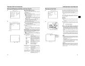
.... 4. Check that the time code that the camera image from the IEEE1394 terminal is displayed in the status display. (When status is in DV format and is input. 4. Synchronize DROP/NON DROP before using . 42 Screen Adjustment PEAKING volume LCD BRIGHT button 180° up 90°... Diopter Adjustment Rotate the eyepiece focusing ring until the viewfinder screen image is running. 9. PREPARATIONS FOR OPERATION Synchronizing with the Time Code of the IEEE1394 (DV)-Connected Master Unit You can use the GY-HD110E as a slave unit. Status display DTCG 00 : 00 : 00 : 00 TC SLAVE LOCK ...
.... 4. Check that the time code that the camera image from the IEEE1394 terminal is displayed in the status display. (When status is in DV format and is input. 4. Synchronize DROP/NON DROP before using . 42 Screen Adjustment PEAKING volume LCD BRIGHT button 180° up 90°... Diopter Adjustment Rotate the eyepiece focusing ring until the viewfinder screen image is running. 9. PREPARATIONS FOR OPERATION Synchronizing with the Time Code of the IEEE1394 (DV)-Connected Master Unit You can use the GY-HD110E as a slave unit. Status display DTCG 00 : 00 : 00 : 00 TC SLAVE LOCK ...

Instructions
Page 28
... tape protect mode, STOP is displayed.) 51 SHOOTING OPERATION „ Checking Recorded Contents in the viewfinder or on the LCD monitor, in DV format and up to recording mode after playback. tor, in RecordStandby Mode (Recording Check Function) This function is available only when the GY...-HD110 is played back. After playback, the camcorder returns to standby mode at TAPE END. "HEAD CLEANING REQUIRED!" Once recording has started, the FRONT TALLY lamp and BACK TALLY lamp light red...
... tape protect mode, STOP is displayed.) 51 SHOOTING OPERATION „ Checking Recorded Contents in the viewfinder or on the LCD monitor, in DV format and up to recording mode after playback. tor, in RecordStandby Mode (Recording Check Function) This function is available only when the GY...-HD110 is played back. After playback, the camcorder returns to standby mode at TAPE END. "HEAD CLEANING REQUIRED!" Once recording has started, the FRONT TALLY lamp and BACK TALLY lamp light red...

Instructions
Page 30
... STOP button. Pressing the REW button executes search of videocassettes: • MiniDV videocassette • DVCAM videocassette Tapes recorded in the case of DV input. (GY-HD110U/GY-HD111E only)) When the GY-HD110 is used in the viewfinder or through the video output connector. • ...reverse direction. Set the AUDIO menu screen. • AUDIO MONITOR Items MIX STEREO : Outputs mixed audio : Outputs stereo audio • PB AUDIO CH [DV] Items CH1/2 MIX CH3/4 : To reproduce the sound (CH-1, CH-2) recorded during shooting. : To reproduce the sound recorded during the search. 54...
... STOP button. Pressing the REW button executes search of videocassettes: • MiniDV videocassette • DVCAM videocassette Tapes recorded in the case of DV input. (GY-HD110U/GY-HD111E only)) When the GY-HD110 is used in the viewfinder or through the video output connector. • ...reverse direction. Set the AUDIO menu screen. • AUDIO MONITOR Items MIX STEREO : Outputs mixed audio : Outputs stereo audio • PB AUDIO CH [DV] Items CH1/2 MIX CH3/4 : To reproduce the sound (CH-1, CH-2) recorded during shooting. : To reproduce the sound recorded during the search. 54...
Instructions
Page 31
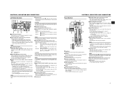
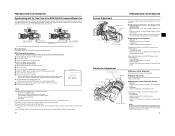
...Composite cable IEEE 1394 HDV DV DC INPUT LINE OUTPUT Component cable CHANGE 1394 SWITCH „ Displaying Alarms • CHANGE 1394 SWITCH Displayed when the setting for the input/output video format from the video signal output connec- Set the camcorder to . 7. Recording unit... output terminal during tape playback. • PB TAPE item: Select whether to the camcorder as possible, as shown in the figure. 2. Composite cable or Component cable PB VIDEO/Y IEEE 1394 HDV DV LINE OUTPUT connector 1. VIDEO FORMAT menu screen 5. Normally, use the "AUTO" setting...
...Composite cable IEEE 1394 HDV DV DC INPUT LINE OUTPUT Component cable CHANGE 1394 SWITCH „ Displaying Alarms • CHANGE 1394 SWITCH Displayed when the setting for the input/output video format from the video signal output connec- Set the camcorder to . 7. Recording unit... output terminal during tape playback. • PB TAPE item: Select whether to the camcorder as possible, as shown in the figure. 2. Composite cable or Component cable PB VIDEO/Y IEEE 1394 HDV DV LINE OUTPUT connector 1. VIDEO FORMAT menu screen 5. Normally, use the "AUTO" setting...

Instructions
Page 32
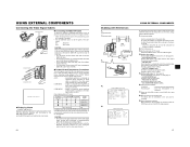
...on again. • If you want to be heard momentarily from this camcorder to turn the power to the device connected to match the HDV/DV signal frame rate input from the playback device in the camcorder. Turn ON both devices on the GY-HD110 to VTR mode. Set ...cable. 3. Set the IEEE1394 switch on both devices to another video) 1. MEMO In HDV format, the UB set in DV format. MEMO Depending on the VTR indicator. 5. This camcorder Recording unit : Recorded videocassette tape : Videocassette you turn on the player, sound may not be possible in some cases even...
...on again. • If you want to be heard momentarily from this camcorder to turn the power to the device connected to match the HDV/DV signal frame rate input from the playback device in the camcorder. Turn ON both devices on the GY-HD110 to VTR mode. Set ...cable. 3. Set the IEEE1394 switch on both devices to another video) 1. MEMO In HDV format, the UB set in DV format. MEMO Depending on the VTR indicator. 5. This camcorder Recording unit : Recorded videocassette tape : Videocassette you turn on the player, sound may not be possible in some cases even...
Instructions
Page 33
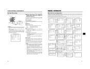
...132; Connections Use the GY-HD110 as on this unit, interrupting the backup recording image. X See page 81. „ Backup unit • Place in HDV/DV signal input mode. * Depending on the used component, it may deviate from what they should be at the points where the recording is started or...8226; Insert the tape and set the BACK SPACE [HDV] item. The items on the OTHERS [2/2] menu screen. IEEE1394 switch PB VIDEO/Y IEEE 1394 HDV DV PR DC INPUT LINE OUTPUT IEEE1394 Master unit GY-HD110 Backup unit Signal flow IEEE1394 cable CAUTION • Set the IEEE1394 switch on both devices...
...132; Connections Use the GY-HD110 as on this unit, interrupting the backup recording image. X See page 81. „ Backup unit • Place in HDV/DV signal input mode. * Depending on the used component, it may deviate from what they should be at the points where the recording is started or...8226; Insert the tape and set the BACK SPACE [HDV] item. The items on the OTHERS [2/2] menu screen. IEEE1394 switch PB VIDEO/Y IEEE 1394 HDV DV PR DC INPUT LINE OUTPUT IEEE1394 Master unit GY-HD110 Backup unit Signal flow IEEE1394 cable CAUTION • Set the IEEE1394 switch on both devices...


