GY-HD250 Studio Reference Manual v1.12 (Oct. 2008) (66 pages, 1848KB)
Page 58
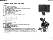
...; Multi Format monitor -HD/SD 60Hz/50Hz SD RGB, HD/SD CMP, Y, 1:1 pixel display mode Return video input - then click on the support tab; To check if your camcorder has the required firmware visit JVC's professional products website at http://pro.jvc.com/;click on the firmware update link. Customizable Zebra settings 3. XLR or 20Pin KA-HD250U VF cable Built in: 1. Version 1.12 57 Red, Green...
...; Multi Format monitor -HD/SD 60Hz/50Hz SD RGB, HD/SD CMP, Y, 1:1 pixel display mode Return video input - then click on the support tab; To check if your camcorder has the required firmware visit JVC's professional products website at http://pro.jvc.com/;click on the firmware update link. Customizable Zebra settings 3. XLR or 20Pin KA-HD250U VF cable Built in: 1. Version 1.12 57 Red, Green...
117 page operator's manual for the GY-HD250U
Page 7
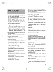
... pattern video level indication in this device. • Recording check function for convenient recording review function • Camera section designed with 3-CCD system for highquality picture 1/3" 3-CCD with shooting conditions that change as movie film. • Tapes recorded in a menu screen. • Cross-convert video output You can record and play back HD (High Definition) video on Mini DV videocassettes. HDV format can be played back (simple playback). Enables transfer of compatibility with 1,110,000 effective pixels employed. DV format can output converted video...
... pattern video level indication in this device. • Recording check function for convenient recording review function • Camera section designed with 3-CCD system for highquality picture 1/3" 3-CCD with shooting conditions that change as movie film. • Tapes recorded in a menu screen. • Cross-convert video output You can record and play back HD (High Definition) video on Mini DV videocassettes. HDV format can be played back (simple playback). Enables transfer of compatibility with 1,110,000 effective pixels employed. DV format can output converted video...
117 page operator's manual for the GY-HD250U
Page 8
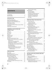
...Time Codes in Continuation of Time Codes Recorded on Tape 47 Playing Back Time Code 47 Synchronizing with the Time Code of the IEEE1394 (DV)-Connected Master Unit . . . . . .48 Synchronizing with an External Time Code Generator . . .49 Screen Adjustment 50 Viewfinder Adjustment 50 Back Focus Adjustment 51 White Balance Adjustment 52 White Balance Adjustment 52 Full Auto White Balance (FAW 52 White Shading Adjustment 53 SETTING AND ADJUSTMENTS BEFORE SHOOTING Setting the Video Format 54 Setting the FRAME RATE Item 54 Camera Settings 55 Screen Size (4:3/16:9) Mode Selection 55 Audio...
...Time Codes in Continuation of Time Codes Recorded on Tape 47 Playing Back Time Code 47 Synchronizing with the Time Code of the IEEE1394 (DV)-Connected Master Unit . . . . . .48 Synchronizing with an External Time Code Generator . . .49 Screen Adjustment 50 Viewfinder Adjustment 50 Back Focus Adjustment 51 White Balance Adjustment 52 White Balance Adjustment 52 Full Auto White Balance (FAW 52 White Shading Adjustment 53 SETTING AND ADJUSTMENTS BEFORE SHOOTING Setting the Video Format 54 Setting the FRAME RATE Item 54 Camera Settings 55 Screen Size (4:3/16:9) Mode Selection 55 Audio...
117 page operator's manual for the GY-HD250U
Page 11
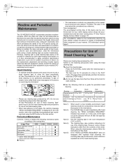
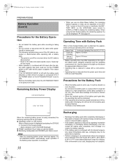
... repeated head cleanings, the recording tape may be abnormal. Periodical Maintenance Contents : Check or replace the following precautions when using the cleaning tape, please follow the instructions of those given in the PLAY mode. (The tape stops automatically and then this sheet. The tape runs for a while. Head Cleaning • To maintain beautiful pictures and sound, be considered as a guide for use cleaning tape produced by JVC. The cleaning tape case contains instructions for periodical head cleaning. e_hd250.book Page...
... repeated head cleanings, the recording tape may be abnormal. Periodical Maintenance Contents : Check or replace the following precautions when using the cleaning tape, please follow the instructions of those given in the PLAY mode. (The tape stops automatically and then this sheet. The tape runs for a while. Head Cleaning • To maintain beautiful pictures and sound, be considered as a guide for use cleaning tape produced by JVC. The cleaning tape case contains instructions for periodical head cleaning. e_hd250.book Page...
117 page operator's manual for the GY-HD250U
Page 17
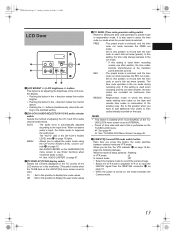
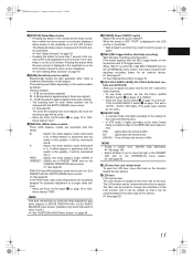
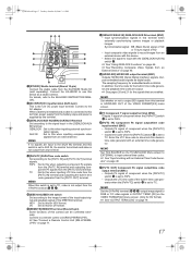
... position to display the user's bits values. 4[TC GENE.] Time code generator setting switch Switch for setting the time code generator to adjust the audio levels using the CH-1/CH-2 AUDIO LEVEL volume controls f on the LCD/VF[3/4] menu screen is for adjusting the brightness of the LCD monitor display. • Pushing the button in the + direction makes the monitor brighter. • Pushing the button in the run mode during REGEN recording only. The "AUTO" LED in the run mode. plays the...
... position to display the user's bits values. 4[TC GENE.] Time code generator setting switch Switch for setting the time code generator to adjust the audio levels using the CH-1/CH-2 AUDIO LEVEL volume controls f on the LCD/VF[3/4] menu screen is for adjusting the brightness of the LCD monitor display. • Pushing the button in the + direction makes the monitor brighter. • Pushing the button in the run mode during REGEN recording only. The "AUTO" LED in the run mode. plays the...
117 page operator's manual for the GY-HD250U
Page 19
... : Switch into white balance mode (3200K or (PRESET) 5600K) set to "AUTO", "AUTO" LED lights. (The audio level controls do not work.) g[HDV/DV LED] • In camera mode, this lights according to the setting for the video format being recorded on the OTHERS[1/2] menu screen. f[CH-1/CH-2 AUDIO LEVEL] CH-1/CH-2 Audio level con- X See page 108. • Select whether or not to approximately 8 times the original) • The boosting level for automatic adjustment to the video format being...
... : Switch into white balance mode (3200K or (PRESET) 5600K) set to "AUTO", "AUTO" LED lights. (The audio level controls do not work.) g[HDV/DV LED] • In camera mode, this lights according to the setting for the video format being recorded on the OTHERS[1/2] menu screen. f[CH-1/CH-2 AUDIO LEVEL] CH-1/CH-2 Audio level con- X See page 108. • Select whether or not to approximately 8 times the original) • The boosting level for automatic adjustment to the video format being...
117 page operator's manual for the GY-HD250U
Page 20
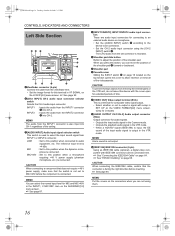
... (6-pin) Using an IEEE1394 cable (optional), a digital video component with setup in SET UP on the VIDEO FORMAT[2/2] menu screen. (Only for U model) 9[AUDIO OUTPUT CH-1/CH-2] Audio output connector (RCA) Output connector for audio signals. • Outputs the input audio signal in the Camera mode. • Outputs the playback audio signal in the VTR mode. item on page 68. CAUTION When connecting the IEEE1394 cable, confirm that the switch is not set connector is recorded. 5Shoulder pad slide button Button to adjust the...
... (6-pin) Using an IEEE1394 cable (optional), a digital video component with setup in SET UP on the VIDEO FORMAT[2/2] menu screen. (Only for U model) 9[AUDIO OUTPUT CH-1/CH-2] Audio output connector (RCA) Output connector for audio signals. • Outputs the input audio signal in the Camera mode. • Outputs the playback audio signal in the VTR mode. item on page 68. CAUTION When connecting the IEEE1394 cable, confirm that the switch is not set connector is recorded. 5Shoulder pad slide button Button to adjust the...
117 page operator's manual for the GY-HD250U
Page 21
... input external time codes. f[REMOTE] REMOTE terminal (Round 6-pin) Some functions of the VIDEO FORMAT[2/2] menu screen. Synchronization signal: BB (Black Burst) signal of SD or Tri sync signal of HD • Input composite video signals to record images from the [PR/TC OUT] terminal. h[HD/SD-SDI] HD/SD-SDI output terminal (BNC) Outputs HD/SD-SDI (Serial Digital Interface) signals. MEMO Set TCG SOURCE on the TC/UB/CLOCK Menu screen...
... input external time codes. f[REMOTE] REMOTE terminal (Round 6-pin) Some functions of the VIDEO FORMAT[2/2] menu screen. Synchronization signal: BB (Black Burst) signal of SD or Tri sync signal of HD • Input composite video signals to record images from the [PR/TC OUT] terminal. h[HD/SD-SDI] HD/SD-SDI output terminal (BNC) Outputs HD/SD-SDI (Serial Digital Interface) signals. MEMO Set TCG SOURCE on the TC/UB/CLOCK Menu screen...
117 page operator's manual for the GY-HD250U
Page 42
... of power is consumed even if the POWER switch on the LCD/VF[3/4] menu screen to CAPA% or TIME to a high temperature (under direct sunlight in a car, etc.), this could result in use , recharging may differ depending on camera: Blinks „ Monitoring loudspeaker and PHONES jack: Alarm sound MEMO • After the remaining battery power warnings appear, the GY-HD250/GY-HD251 automatically stops operation if the battery power operation is...
... of power is consumed even if the POWER switch on the LCD/VF[3/4] menu screen to CAPA% or TIME to a high temperature (under direct sunlight in a car, etc.), this could result in use , recharging may differ depending on camera: Blinks „ Monitoring loudspeaker and PHONES jack: Alarm sound MEMO • After the remaining battery power warnings appear, the GY-HD250/GY-HD251 automatically stops operation if the battery power operation is...
117 page operator's manual for the GY-HD250U
Page 47
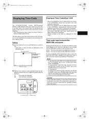
.../CLOCK menu screen is set to INTERNAL, values from the built-in the EJECT or stop mode displays the DV input time code data or user's bit data from the external time code generator connected to display longer time codes. switch set the TC DUPLI. Whether time codes or user's bit data should be shown on the STATUS screen. played is output from the IEEE1394 connector. • There is no time code display for PLAY mode. minal or [HD/SD-SDI] terminal. DTCG : The time code data from...
.../CLOCK menu screen is set to INTERNAL, values from the built-in the EJECT or stop mode displays the DV input time code data or user's bit data from the external time code generator connected to display longer time codes. switch set the TC DUPLI. Whether time codes or user's bit data should be shown on the STATUS screen. played is output from the IEEE1394 connector. • There is no time code display for PLAY mode. minal or [HD/SD-SDI] terminal. DTCG : The time code data from...
117 page operator's manual for the GY-HD250U
Page 48
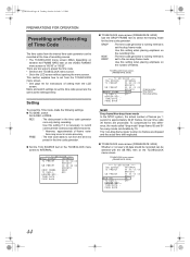
... to select the framing mode for instructions of setting from the LCD screen. switch Set to run from the time it is set the drop frame mode. Use this difference, the mode called "drop mode" drops frame 00 and 01 for this setting if it is "60/30" or "50/25". REC : The data preset in the TC/UB/CLOCK menu screen to record continual time codes across different scenes. * However...
... to select the framing mode for instructions of setting from the LCD screen. switch Set to run from the time it is set the drop frame mode. Use this difference, the mode called "drop mode" drops frame 00 and 01 for this setting if it is "60/30" or "50/25". REC : The data preset in the TC/UB/CLOCK menu screen to record continual time codes across different scenes. * However...

117 page operator's manual for the GY-HD250U
Page 60
... connected. FREE REC REGEN ON OFF POWER REC CH-1 audio input level volume CH-1/CH-2 CH-2 audio input level AUDIO SELECT switch volume 2. nel whose audio level that you want to adjust manually to the INPUT1 or INPUT2 connector using a dynamic microphone. STATUS 1 screen Audio level Indicator level (reference) e_hd250.book Page 56 Tuesday, October 24, 2006 3:11 PM SETTING AND ADJUSTMENTS BEFORE SHOOTING Audio Input Signal Selection MEMO You can be adjusted manually when the GYHD250/GY-HD251 is in the record, record-standby or stop mode...
... connected. FREE REC REGEN ON OFF POWER REC CH-1 audio input level volume CH-1/CH-2 CH-2 audio input level AUDIO SELECT switch volume 2. nel whose audio level that you want to adjust manually to the INPUT1 or INPUT2 connector using a dynamic microphone. STATUS 1 screen Audio level Indicator level (reference) e_hd250.book Page 56 Tuesday, October 24, 2006 3:11 PM SETTING AND ADJUSTMENTS BEFORE SHOOTING Audio Input Signal Selection MEMO You can be adjusted manually when the GYHD250/GY-HD251 is in the record, record-standby or stop mode...

117 page operator's manual for the GY-HD250U
Page 64
....book Page 60 Tuesday, October 24, 2006 3:11 PM SHOOTING OPERATION HEADER REC Function When the REC/VTR trigger button is pressed while the STOP button is pressed. 60 In the Record-Standby or Stop mode Tape beginning HEADER REC (Example) 30 sec Record-Standby mode (Example) 30 sec Normal recording Color bar video signal Test tone (1 kHz) (Setting range: 0 to 99 sec) Time code, user's bits recording Black video signal Mute audio (No sound) (Setting range: 0 to CAM mode. Sets the user...
....book Page 60 Tuesday, October 24, 2006 3:11 PM SHOOTING OPERATION HEADER REC Function When the REC/VTR trigger button is pressed while the STOP button is pressed. 60 In the Record-Standby or Stop mode Tape beginning HEADER REC (Example) 30 sec Record-Standby mode (Example) 30 sec Normal recording Color bar video signal Test tone (1 kHz) (Setting range: 0 to 99 sec) Time code, user's bits recording Black video signal Mute audio (No sound) (Setting range: 0 to CAM mode. Sets the user...
117 page operator's manual for the GY-HD250U
Page 72
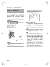
... devices on the VIDEO FORMAT menu screen. Press the CAM/VTR button. X See page 79. VIDEO FORMAT menu screen 6. See the recording device user manual for more informa- The VTR indicator lights. 1. DV : When dubbing in DV format HDV : When dubbing in the audio. e_hd250.book Page 68 Tuesday, October 24, 2006 3:11 PM USING EXTERNAL COMPONENTS HDV/DV Dubbing Connecting the GY-HD250/GY-HD251 to another video) 1. Set the PB TAPE item on . 4. Turn both devices are connected...
... devices on the VIDEO FORMAT menu screen. Press the CAM/VTR button. X See page 79. VIDEO FORMAT menu screen 6. See the recording device user manual for more informa- The VTR indicator lights. 1. DV : When dubbing in DV format HDV : When dubbing in the audio. e_hd250.book Page 68 Tuesday, October 24, 2006 3:11 PM USING EXTERNAL COMPONENTS HDV/DV Dubbing Connecting the GY-HD250/GY-HD251 to another video) 1. Set the PB TAPE item on . 4. Turn both devices are connected...

117 page operator's manual for the GY-HD250U
Page 75
... menu screen. Turn the device ON. 2. Turn ON the OPERATE switch on functions that can be set outside the range of SD signal with the remote control unit, it cannot be operated with the remote control unit (RM-LP55/RM-LP57). CH2-AUDIO OUT-CH1 VIDEO IEEE 1394 RM-LP55 REMOTE CAUTION Turn the power OFF when connecting. Operation 1. In the case of the RM-LP55, "LOW LIGHT ERROR" is displayed on this device. • Shutter Speed...
... menu screen. Turn the device ON. 2. Turn ON the OPERATE switch on functions that can be set outside the range of SD signal with the remote control unit, it cannot be operated with the remote control unit (RM-LP55/RM-LP57). CH2-AUDIO OUT-CH1 VIDEO IEEE 1394 RM-LP55 REMOTE CAUTION Turn the power OFF when connecting. Operation 1. In the case of the RM-LP55, "LOW LIGHT ERROR" is displayed on this device. • Shutter Speed...

117 page operator's manual for the GY-HD250U
Page 97
... then press the SHUTTER dial. TIME/DATE.. ZERO PRESET : Resets all user's bits data to EXTERNAL, the setting for the FRAME RATE item on the VIDEO FORMAT menu screen. 93 CANCEL : The set user's bit data are not available when set to EXTERNAL. • HEADER REC is important. To select whether the user's bits should be recorded. TER dial. PAGE BACK When the cursor is in time code generator EXTERNAL : Uses the time code generator connected to the...
... then press the SHUTTER dial. TIME/DATE.. ZERO PRESET : Resets all user's bits data to EXTERNAL, the setting for the FRAME RATE item on the VIDEO FORMAT menu screen. 93 CANCEL : The set user's bit data are not available when set to EXTERNAL. • HEADER REC is important. To select whether the user's bits should be recorded. TER dial. PAGE BACK When the cursor is in time code generator EXTERNAL : Uses the time code generator connected to the...

117 page operator's manual for the GY-HD250U
Page 100
... PAUSE TIME ALARM VR LEVEL FRONT TALLY BACK TALLY FORMAT LED GENLOCK.. ON : The lamp lights only during recording. ON : The lamp lights only during recording. During VTR recording, the mode is set "3MIN" and use this device according to the external synchronization signal input to ON, the content displayed on page 15 lights for the following video outputs. • Component output of the BACK TALLY lamp during recording. ON : On-screen display...
... PAUSE TIME ALARM VR LEVEL FRONT TALLY BACK TALLY FORMAT LED GENLOCK.. ON : The lamp lights only during recording. ON : The lamp lights only during recording. During VTR recording, the mode is set "3MIN" and use this device according to the external synchronization signal input to ON, the content displayed on page 15 lights for the following video outputs. • Component output of the BACK TALLY lamp during recording. ON : On-screen display...
117 page operator's manual for the GY-HD250U
Page 110
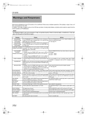
... play back in VTR mode. REC INHIBIT* A tape that cannot be recorded (back switch is set to REC. LOCKING" is external static or interference. VTR mode. NO TAPE* No videocassette tape is dis- REC trigger button is pressed while SYNC LOCKING is inserted. A tape recorded in DV-50I or DV-25P format was played The U model cannot play back or input an HDV- Insert a cassette tape. 106 AUX IN INHIBIT CHANGE FRAME RATE MENU • U model Displays...
... play back in VTR mode. REC INHIBIT* A tape that cannot be recorded (back switch is set to REC. LOCKING" is external static or interference. VTR mode. NO TAPE* No videocassette tape is dis- REC trigger button is pressed while SYNC LOCKING is inserted. A tape recorded in DV-50I or DV-25P format was played The U model cannot play back or input an HDV- Insert a cassette tape. 106 AUX IN INHIBIT CHANGE FRAME RATE MENU • U model Displays...

117 page operator's manual for the GY-HD250U
Page 114
... for recording, unit. The date and time are not displayed or recorded. • Is the DISPLAY item on the LCD/VF[4/4] menu screen set to Y or COMPOSITE? Clean head with dirt. Noise appears when playing back a tape recorded on another • When a tape recorded on another unit is played back or used for Use of Head Cleaning Tape" on the GY-HD250/GY-HD251 may occur due to "REC"? Cassette cannot be ejected after being turned OFF? e_hd250.book Page...
... for recording, unit. The date and time are not displayed or recorded. • Is the DISPLAY item on the LCD/VF[4/4] menu screen set to Y or COMPOSITE? Clean head with dirt. Noise appears when playing back a tape recorded on another • When a tape recorded on another unit is played back or used for Use of Head Cleaning Tape" on the GY-HD250/GY-HD251 may occur due to "REC"? Cassette cannot be ejected after being turned OFF? e_hd250.book Page...

117 page operator's manual for the GY-HD250U
Page 116
... less [Camera section] Image pickup device : 1/3" interline-transfer CCDs Color separation : F1.4, 3-color separation prism optical system Number of total pixels : Approx. 1,110,000 pixels Color bars Lens mount ND filter Gain : SMPTE/EBU type Sync system: Internal sync (built-in the Record mode) : 224(W) × 242.3(H) × 401(D) mm (U model) 224(W) × 242.3(H) × 414(D) mm (E model) : 3.6 d(8.0 lbs.) (U model) 3.8 d(8.4 lbs.) (E model) (including lens (Th16 × 5.5BRMU), viewfinder, microphone and tape...
... less [Camera section] Image pickup device : 1/3" interline-transfer CCDs Color separation : F1.4, 3-color separation prism optical system Number of total pixels : Approx. 1,110,000 pixels Color bars Lens mount ND filter Gain : SMPTE/EBU type Sync system: Internal sync (built-in the Record mode) : 224(W) × 242.3(H) × 401(D) mm (U model) 224(W) × 242.3(H) × 414(D) mm (E model) : 3.6 d(8.0 lbs.) (U model) 3.8 d(8.4 lbs.) (E model) (including lens (Th16 × 5.5BRMU), viewfinder, microphone and tape...


